1
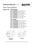
MedV iew Software User Manual Ver 1.0 MedView Software user manual Version: Ver1.0 Copyright Our company owns all rights of this unpublished work and intends to maintain it as a confidential work. We may also seek to maintain this work as an unpublished copyright. This publication is to be used solely for the purpose of reference or operation of our software system. No part of this work can be disseminated for other purposes. In the event of inadvertent or deliberate publication, we intend to enforce its right to this work under copyright laws as a published work. Those having access to this work may not copy, use, or disclose the information in this work unless expressly authorized by our company. All information contained in this publication is believed to be correct. We shall not be liable for errors contained herein nor for incidental or consequential damages in connection with the furnishing, performance, or use of this material. The information this publication refers to is protected by copyrights or patents and does not convey any license under the patent rights of our company, nor the rights of others. We do not assume any liability arising out of any infringements of patents or other rights of third parties. Content of the manual is subject to change without prior notice. ALL RIGHTS RESERVED © Beijing Choice Electronic Technology Co., Ltd. All trademarks are the property of Beijing Choice Electronic Technology Co., Ltd. unless otherwise noted. Bluetooth® and the Bluetooth® Logo are registered trademarks of Bluetooth® SIG, Inc. Windows XP®, Windows Vista® and Microsoft® are registered trademarks of microsoft. 2 MedView Software user manual Version: Ver1.0 CONTENT 1. GENERAL DESCRIPTION ...............................................................................................................4 2. SOFTWARE INSTALLATION ...........................................................................................................4 3. SOFTWARE OPERATION ................................................................................................................8 3.1 USB Transmission .....................................................................................................................8 3.2 Save Data ..................................................................................................................................12 3.3 Manual search for serial port ..................................................................................................12 3.4 Bluetooth® data transmission .................................................................................................15 3.5 Open Saved Data......................................................................................................................22 3.6 Check out the SpO2 Pr event time… ......................................................................................22 3.6 Management of Patient information .......................................................................................22 3.6.1 Edit Patient Info ...........................................................................................................22 3.6.2 Edit Patient Title...........................................................................................................23 3.7 Mode of Data Record ...............................................................................................................24 3.7.1 Trend .............................................................................................................................24 3.7.2 Table..............................................................................................................................25 3.7.3 Analysis ........................................................................................................................25 3.8 Options .....................................................................................................................................26 3.8.1 Roll Step .......................................................................................................................26 3.8.2 Analysis Setup .............................................................................................................27 3.8.3 Unit Setup.....................................................................................................................28 3.9 Open Other ID Data ..................................................................................................................28 3.10 Print.........................................................................................................................................29 3.11 About(A) ..................................................................................................................................29 4. SOFTWARE UNINSTALL ...............................................................................................................31 Appendix:...........................................................................................................................................33 3 MedView Software user manual Version: Ver1.0 1. GENERAL DESCRIPTION The MedView contains a series of data management softwares which are designed according to different type of pulse oximeters/monitors. The series of softwares consist of three individual softwares those are MedView-OP-B, MedView-OP-C and MedView-OP-D. MedView-OP-B: MD300K1/ MD300K1-E/ MD300K21/ MD300K12/ MD300M11/ MD300W1/ MD300W11 MedView-OP-C: MD300I/ MD300I2/ MD300I12/ MD300P/ MD2000A/ MD2000A-E/ MD2000A-V MedView-OP-D: MD300C318/ MD300C316/ MD300W2 An entire operation system consists of one pulse oximeter/monitor, one computer, a piece of MedView software CD, and a USB cable. The waveforms and data saved in the device can be uploaded to a computer through the USB cable or Bluetooth® and managed by this software. MedView software is convenient for users to view, manage and save data records including waveforms, pulse rates and analysis results. It provides the function of printing under patient administration and various modes. Patient administration distinguishes datum from their IDs which range from 1 to 127. So it could save 127 patients’ data at most. The records for the same ID will be regarded as the same patient’s measurement. The ID number in “Data Info” is the ID number in the corresponding pulse oximeter/monitor, thus it can not be changed on the transmission software. The instruction manual is applied to the three individual MedView softwares those have the similar operations.. The manual is illustrated by MedView-OP-D software and the MD300C318 Pulse Oximeter. Tip: It is suggested that the software should be run on the Windows XP® patch SP2/SP3, Windows 7 and Windows Vista® 32 bit Edition. 32 bit Edition with the Notes: Read the manual carefully before running the software! Please make sure that there is at least one record saved in the Pulse Oximeter/Monitor before data upload. Power on the Pulse Oximeter/Monitor and set the mode of the device to data transmission. 2. SOFTWARE INSTALLATION Put the attached installation CD into computer’s CD driver, the CD will run automatically and then the following interface will appear, as shown in Figure 2-1. Figure 2-1 4 MedView Software user manual Version: Ver1.0 (1) Click “Install MedView Software Ver:X.X.X” in fig.2-1 to begin the installshield wizard of MedView Software. Then Figure 2-2 will appear. Figure 2-2 (2) Click “Next” button in Figure 2-2, then Figure 2-3 will appear. Figure 2-3 5 MedView Software user manual Version: Ver1.0 (3) Click “Yes” button to accept the license agreement in Figure 2-3, then Figure 2-4 will appear. Figure 2-4 (4) Click “Next” button in Figure 2-4, the Figure 2-5 will appear and the installation files are saved in “C:\Choice\MedView”. Also, users can click “Browse” button to choose the path for saving the installation files. Figure 2-5 6 MedView Software user manual Version: Ver1.0 (5) To choose MedView setup type, click the radio button “Typical”, “Compact” or “Custom” in Figure 2-5, then click “Next”, the Figure 2-6 will appear. Figure 2-6 (6) Click “Next” to select the default program folder for saving the program icon, or type another folder name in blank as shown as Figure 2-6, the following figure will appear. Figure 2-7 7 MedView Software user manual Version: Ver1.0 (7) Click “Next” in Figure 2-7, the following figure will appear. It indicates that the installation of MedView has been finished on your computer. Figure 2-8 (8) Click “Finish” button in Figure 2-8, the shortcut icon will be created on the desktop, as shown in Figure 2-9. The shortcut and Uninstall MedView icons are added into “Start” menu on the left bottom of desktop, as shown in Figure 2-10. Figure 2-9 Figure 2-10 3. SOFTWARE OPERATION After installing the MedView software, The data saved in the pulse oximeter/Monitor can be transmitted to the computer by USB cable or Bluetooth®. Then, users can manage the data. 3.1 USB Transmission This software system will search the corresponding serial port automatically by which the pulse oximeter/monitor communicates with the computer. If that is failed, the manual search for serial port will be effective, refers to section 3.3. The manual search function applies to data transmission with USB cable. 3.1.1 Equipment Connection Before data transmission by USB cable, connect the pulse oximeter/monitor to the USB interface of the compute by the USB cable. Note:For the device configured with the function of Bluetooth® transmission, such as MD300C318 and MD300W2, set the Bluetooth® transmission off before starting data transmission by USB cable. 8 MedView Software user manual Version: Ver1.0 3.1.2 Double click the icon “MedView” on the desktop, the following screen will appear, as shown in Figure 3-1. Figure.3-1 3.1.3 Click the “New Date Capture” from the “File(F)” drop-down menu item, as shown in Figure 3-2. A window notifying the total number of data items uploaded appears, refer to fig.3-3. Figure 3-2 Figure 3-3 9 MedView Software user manual Version: Ver1.0 3.1.4 Click the “OK” button in fig.3-3 to enter the “New Data Capture” dialog box. The data transmission from the device to the MedView software begins to proceed. Refer to fig.3-4. Figure.3-4 Tips: (1).Stop: Click the “Stop” button, the transmission process is terminated. (2).Cancel: click “Cancel” button in any interface, the system will exit the current operation. (3).Extend: This function applies to manually searching serial port by which the device communicates with the computer. Figure 3-5 10 MedView Software user manual Version: Ver1.0 3.1.5 Click a piece of data record which you want to manage in “Data Info” column, and then click the “Done” button to acquire its report, refer to fig.3-6&3-7. Figure 3-6 Figure 3-7 11 MedView Software user manual Version: Ver1.0 3.1.6 Delete Data: Click “Delete Data” button in Figure 3-5, the following figure appears, as shown in Figure 3-8. If clicking the “Yes” button, all the data in the device will be deleted, as shown in figure 3-9. Figure 3-8 Figure 3-9 3.2 Save Data Click “Save Data(S)…” from the “File(F)” drop-down menu item, as shown in Figure 3-10. Note: Make sure that save the data into your computer after data transmission every time for later management. The saved data file has the extension of .dat、.txt or.xls. Figure 3-10 3.3 Manual search for serial port If serial port by which the device communicates with PC fails to be found,It is recommended to apply the manual search for serial port. 3.3.1 Click “Extend>>“ button as shown in Figure 3-6, the interface is shown as the following figure. 12 MedView Software user manual Version: Ver1.0 Figure 3-11 3.3.2 Return to the desktop of compute, right click “My Computer”->“Properties”, refer to fig.3-12. Figure 3-12 Click “Hardware” item from System Properties panel, as shown in Figure 3-13. 13 MedView Software user manual Version: Ver1.0 Figure 3-13 3.3.3 Click “Device Manager” button in the panel as shown in Figure 3-13. The following screen appears, “CP2101 USB to UART Bridge Controller (COMx)” indicates that the serial port is COMx by which the device communicates with the computer (E.g. “COM3” in Figure 3-14). Figure 3-14 14 MedView Software user manual Version: Ver1.0 3.3.4 Select the found “COMx” from the “PORT” drop-down menu, (E.g. “COM3” in Figure 3-14). Then click “Start” button to capture the data. The figure 3-4 will appear. Figure 3-15 3.4 Bluetooth® data transmission The Bluetooth® data transmission applies to the oximeter MD300C318 and MD300W2. The following operation is only suitable for the computer configured Microsoft® Bluetooth®. Notes: Before uploading data, read the instruction manual for MD300C318/ W2 carefully. Set the transmission mode of the oximeter to “Blue Tooth: ON”. Insert the attached Bluetooth® adapter into the USB port. 3.4.1 Click “Find Bluetooth® radio” from “File(F)” drop-down menu items as shown in Figure 3-16. The Bluetooth Information window appears, refer to Fig.3-17. 15 MedView Software user manual Version: Ver1.0 Figure 3-16 3.4.2 There are three methods of searching Bluetooth® devices, (1). Select “Show Remembered” (2). Select “Issue Inquiry” and “Show Remembered” (3). Select “Wizard”. Figure 3-17 (1). Select “Show Remembered” in the interface as shown in Figure 3-17, then click “Scan Radio” or “Rescan Radio”, as shown in Figure 3-18. 16 MedView Software user manual Version: Ver1.0 Figure 3-18 After the Bluetooth device is found, it appears in the blank. Click the Bluetooth® device by the right mouse button, and click “Connect” item from the drop-down menu,refer to Figure 3-19. Figure 3-19 When the connection is created successfully, the following interface appears, as shown in Figure 3-20. Figure 3-20 17 MedView Software user manual Version: Ver1.0 If clicking the “OK” button, users can upload data saved in the device to the computer. The ordinal operation is the same as the USB transmission.. (2). Select “Issue Inquiry” and “Show Remembered” in the interface as shown in Figure 3-21. The ordinal operation is the same as when selecting “Show Remembered”. Figure 3-21 (3). Select “Wizard” in the interface as shown in Figure 3-22, the following operation refers to steps Ⅰ~ Ⅳ. Figure 3-22 18 MedView Software user manual Version: Ver1.0 Ⅰ. After choosing “Wizard”, click “Scan Radio” in figure 3-22. the following window appears. Figure 3-23 Ⅱ. Check the button “My device is setup and ready to be found” in Figure 3-23. Click “Next” button, the following screen appears. Figure 3-24 19 MedView Software user manual Version: Ver1.0 ® Ⅲ. Choose and click the Bluetooth device, such as “BCOXM-1”,and click “Next” button. The following window appears. Figure 3-25 Ⅳ. Please check “Let me choose my own passkey” radio button,and type the default passkey 0000 in the corresponding bank. Click “Next”, the following figures 3-26&3-27 appear. Figure 3-26 20 MedView Software user manual Version: Ver1.0 Figure 3-27 Click “Finish” to complete the connection with Bluetooth® device. And the following figure appears. Figure 3-28 The ordinal operation is the same as when selecting “Show Remembered”. Note: If user uses non-microsoft® bluetooth® driver and the driver support bluetooth® virtual serial port for data transmission, the driver will create virtual serial port for the device. When using non-microsoft® bluetooth® driver, choose the corresponding port in “Manual Setup” section. 21 MedView Software user manual Version: Ver1.0 3.5 Open Saved Data Click “Open Saved Data(O)…” from “File(F)” drop-down menu item, as shown in Figure 3-29. Then you can import saved data record from PC. Note that the “Edit”, “Mode”and “Options” menu items are only available after importing data record. Figure 3-29 3.6 Check out the SpO2 Pr event time… Click “Check out the SpO2 Pr event time…” from “File(F)” drop-down menu item, as shown in Figure 3-30. Then you can export the analysis result for desaturation and pulse rate events. The analysis result file is saved with the extension of . txt. Figure 3-30 3.6 Management of Patient information 3.6.1 Edit Patient Info Click “Patient Info” from “Edit” drop-down menu item, as shown in Figure 3-31. 22 MedView Software user manual Version: Ver1.0 Figure 3-31 The following figure will appear, type in the blanks with the patient’s information. That is important for managing and analyzing the measurement data of patients. After finishing the columns, click “Save Info” button to save the information for patient or click “Delete Info” button to delete the information. Or click “Cancel” to cancel the current operation. Figure 3-32 3.6.2 Edit Patient Title Click “Patient Title” from “Edit” drop-down menu item, as shown in Figure 3-33. the “Modify Tile” dialog box appears. Figure 3-33 The name of the patient report can be changed by typing a new name, as shown in Figure 3-34. Click the “OK” button to confirm or “Cancel” to exit the current dialog box. 23 MedView Software user manual Version: Ver1.0 Figure 3-34 3.7 Mode of Data Record 3.7.1 Trend Click “Trend” from “Mode” drop-down menu item to acquire the trend chart such as shown in Figure 3-35. Figure 3-35 The trend graph displays the start date and time, the end date and time. When you move the cursor and click any point on the trend, it displays the value of the point. Additionally. you can acquire the value of your desired point by pressing the Left or Right direction key on the keyboard. 24 MedView Software user manual Version: Ver1.0 3.7.2 Table Click “Table” from “Mode” drop-down menu item to display the data record in table, as shown in Figure 3-36&3-37. Figure 3-36 Figure 3-37 3.7.3 Analysis Click “Analysis” from “Mode” drop-down menu item to acquire the analysis report of the piece of data record. Refer to fig.3-38&3-39. Figure 3-38 25 MedView Software user manual Version: Ver1.0 Figure 3-39 WARNING: The analysis report is only a reference for doctors. DO NOT make any diagnoses depending on the analysis report. 3.8 Options 3.8.1 Roll Step Click “Roll Step” from “Options” drop-down menu item to access the roll step dialog box. Refer to fig.3-40&3-41. Figure 3-40 26 MedView Software user manual Version: Ver1.0 Figure 3-41 Change roll step number by clicking the up button or down button control and then click “OK” or “Cancel” button to confirm or abort the setting. 3.8.2 Analysis Setup Click “Analysis Setup” from “Options” drop-down menu item to access the “Analysis Setup” dialog box. Refer to fig.3-42&3-43. Figure 3-42 The parameters shown in the following dialog box can be set by clicking the up button or down button next to the corresponding blanks. Then click “OK” or “Cancel” to confirm or abort the settings. Figure 3-43 (1) High O2 Saturation Threshold: set the upper value of SpO2, the software can record the that the measured SpO2 is over the upper value. (2) Low O2 Saturation Threshold: set the lower value of SpO2, the software can record the that the measured SpO2 is below the lower value. (3) High Pulse Rate Threshold: set the upper value of pulse rate, the software can record the that the measured pulse rate is over the upper value. (4) Low Pulse Rate Threshold: set the lower value of pulse rate, the software can record the that the measured pulse rate is over the lower value. 27 times times times times MedView Software user manual Version: Ver1.0 (5) Desaturation Event Threshlod: Set the desaturation value of SpO2, the software will record the times that SpO2 has decreased by the desaturation value, compared with the previous SpO2. (6) Pulse Event Threshold: Set the decreased value of pulse rate, the software will record the times that pulse rate has decreased by the value, compared with the previous pulse rate. 3.8.3 Unit Setup Click “Unit Setup” from “Options” drop-down menu item to access the “Unit Setup” dialog box. Refer to fig.3-44&3-45. Figure 3-44 Two unit systems are available, including Britain and Metric systems, as shown in Figure 3-45. Figure 3-45 3.9 Open Other ID Data Click “Open other ID Data” from “File(F)” drop-down menu item to review other ID’ data records. Refer to fig.3-46&3-47. Figure 3-46 28 MedView Software user manual Version: Ver1.0 Figure 3-47 3.10 Print Click “Print” from “File(F)” drop-down menu item to print this piece of data record. The data record can be printed in trend, table and analysis report according to your selected display mode from ”Mode” menu item. Figure 3-48 3.11 About(A) Click “About(A)…” from “About(A)” menu item to see the information of the software. Figure 3-49 Note: When the following prompt windows appear, please check the connection between the device and PC for normal connection or whether the device is turned on. 29 MedView Software user manual Version: Ver1.0 Figure 3-50 Figure 3-51 30 MedView Software user manual Version: Ver1.0 4. SOFTWARE UNINSTALL Click “Uninstall MedView” from “Start” menu on the desktop, as shown in Figure 4-1. Follow the instruction to uninstall MedView software. The uninstall screens are shown below: Figure 4-1 Figure 4-2 Figure 4-3 31 MedView Software user manual Version: Ver1.0 Figure 4-4 32 MedView Software user manual Version: Ver1.0 Appendix: If the USB Driver cannot be installed automatically, the Manual installation is suggested. 1 Click “Browse this CD” icon, the CD folder will be opened, as shown in Figure 1. Figure 1 2 Dblclick the “usbDriver” folder to open it in Figurer 1, the following icon will appear, shown in Figure 2. Figure 2 3 To install USB Driver, dblclick the “setup.exe” icon shown in Figure 2, the following interface will appear. Figure 3 33 MedView Software user manual Version: Ver1.0 (2) Click “Next” button in Figure 3, then Figure 4 will appear. Figure 4 (3)Click the radio button “I accept the terms of the license agreement” in Figure 4, then Figure 5 will appear, click “Next” button and the installation files will be saved in “C:\SiLabs\MCU_2”. Also, users can click “Browse” button to choose the path for saving the installation files. Figure 5 34 MedView Software user manual Version: Ver1.0 (4)Click “Next” button in Figure 5, then Figure 6 will appear. Figure 6 (5) Click “Install” button in Figure 6, then Figure 7 will appear. Figure 7 35 MedView Software user manual Version: Ver1.0 (6) Be sure to select “Launch the CP210x VCP Driver Istaller”, click “Finish” as shown in figure 7, the figure 8 will appear. Click “Change Install Location” to specify the install destination. Then click “Install”, the figure 9 will appear. Figure 8 Figure 9 Manufacturer address: Beijing Choice Electronic Technology Co.,Ltd. Bailangyuan Building B Rm. 1127-1128, Fuxing Road, A36 100039 Beijing PEOPLE’S REPUBLIC OF CHINA 36