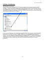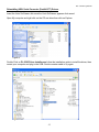
1
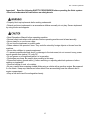
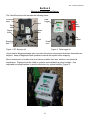
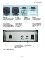
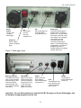
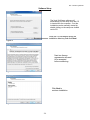
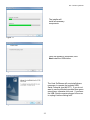
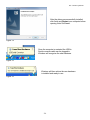
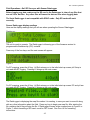
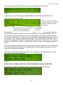
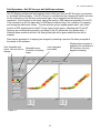
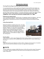
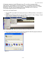
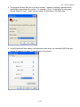
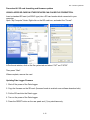
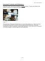
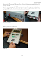
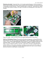
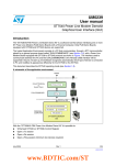
Pub. # OM18-Quad1000 Operating Instructions Quad 1000 Soil EC Mapping System Table of Contents Section 1 1-2 1-3 Warranty Safety Section 2 2-1 2-3 2-4 Electronics Overview and Set-up: EC Surveyor Electronics Overview and Set-up: DataLogger Software Set-up: SoilViewer Section 3 3-1 3-2 Implement Overview and Set-up Additional Assembly Instructions Section 4 4-1 4-2 4-4 4-5 Field Operations—EC Surveyor Field Operations—EC Surveyor with DataLogger Field Operations—EC Surveyor with SoilViewer software Field Operations--Implement Section 5 5-1 5-2 Troubleshooting SoilViewer Troubleshooting Section 6 6-1 6-2 6-4 6-10 6-12 6-16 6-19 6-19 6-20 Maintenance and Service Procedures #1. EC Surveyor signal testing #2. Testing electrical continuity #3. Diagnosing and correcting EC signal problems #4. Spring plunger testing and replacement #5. Diagnosing GPS-related problems #6. Firmware updates and SD card formatting #7. Implement lubrication #8. Maintenance #9. Micro-chip replacement 1-1 Pub. # OM18-Quad1000 Quad 1000 Soil EC Mapping System SoilViewer Version 2.52 Sensor DataLogger Version 1.03 Section 1 Warranty Veris Technologies warrants this product to be free of defects in materials and workmanship for a period of one (1) year from the date of delivery to the purchaser. Veris Technologies will repair or replace any product returned to Salina, Kansas, which appears upon inspection to be defective in materials or workmanship. Veris Technologies will have shall have no obligation under this warranty for the cost of labor, down-time, transportation charges, or for the repair or replacement of any product that has been misused, carelessly handled, modified, or altered. ALL OTHER WARRANTIES OF ANY KIND, WHETHER EXPRESSED OR IMPLIED, INCLUDING BUT NOT LIMITED TO ANY IMPLIED WARRANTY OF MERCHANTABILITY OR OF FITNESS FOR A PARTICULAR PURPOSE AND ALL CLAIMS FOR CONSEQUENTIAL DAMAGES, ARE SPECIFICALLY DISCLAIMED AND EXCLUDED. Safety 1-2 Pub. # OM18-Quad1000 Important! Read the following SAFETY PROCEDURES before operating the Veris system: • Read and understand all instructions on safety decals • Properly block up implements befor working underneath. • Detach and store implements in an area where children normally do not play. Secure implement by using blocks and supports. • Read Operations Manual before operating machine • Review safety instructions with operators before operating machine and at least annually • Never stand on or use tire as a step • Do not tow the implement on public roads. • Riders obstruct the operator’s view. They could be struck by foreign objects or thrown from the machine. • Never allow children to operate equipment. • To prevent possible electrical shock, or damage to the instrument, do not connect to any power source greater than twelve (12) volts DC. • Do not grease or oil implement while it is in operation. • Disk edges are sharp. Be careful when working in this area. • Disconnect battery ground cable (-) before servicing or adjusting electrical systems or before welding on implement. • Remove buildup of mud, oil or debris. • Be very careful when mapping stubble fields using a vehicle with a gasoline engine. Be prepared if a fire starts. Keep crop residue and other debris from accumulating near the exhaust and in engine compartment. • Keep a first aid kit and fire extinguisher handy. 1-3 Pub. # OM18-Quad1000 Section 2 Electronics Overview and Set-up The Veris Electronics kits includes the following items: Protective case DataLogger EC Surveyor SD card reader Serial cable Signal test box SoilViewer software Mtg bracket Signal test load Mtg bracket Power cord Power cord Figure 1. EC Surveyor kit Figure 2. DataLogger kit Use protective shipping/storage case to protect electronics components whenever electronics are shipped. Keep all diagnostics and operations manual with system when mapping. Mount instrument in a location that is as free as possible from dust, vibration, and electrical interference. Display should be visible to operator and shielded from direct sunlight. Use adjustable mounting brackets to position electronics for optimal visibility (Figure 3). Figure 3. 2-1 Pub. # OM18-Quad1000 Figure 4. EC Surveyor (rear) Power port: The Soil EC Surveyor is shipped with an accessory power cord. If an alternative connection is desired, make sure that the unit is properly connected to a power connection that is not controlled by the ignition switch. If connecting directly to the battery, we suggest a 3-amp inline fuse is installed between the battery and the instrument. EC Signal: EC Signal Cable extension from implement attaches to the EC Surveyor here. Route cable properly to prevent damage. Signal test load also attaches here—used to test EC Surveyor. EC Data out: Attach serial cable here and other end to Sensor DataLogger or laptop PC. GPS input: Connect GPS cable here. It is designed to accept GPS input in NMEA 0183 format via an RS232 connector. (GPS must send GGA and either VTG or RMC strings at a 1hz rate, at 4800 baud, 8 data bits, 1 stop bit, no parity.) Figure 5. EC Surveyor (front) Fuse: This allows the fuse to be replaced, with a 1A fastblow fuse, if blown. Data Status: When lit, this green LED indicates data is being sent out serial port. If not lit, EC values are negative or GPS signal not received. Figure 6. DataLogger (rear) 2-2 Power: When lit, this red LED indicates EC Surveyor is powered up. On/Off: Turns power to EC Surveyor on and off. Pub. # OM18-Quad1000 Reset button: Can be used to reboot DataLogger EC: Serial cable from EC Surveyor attaches here. pH: Serial cable from pH Controller (MSP only) attaches here. Alarm Vol: Used to adjust volume of auditory alarm Figure 7. DataLogger (front) Memory Card slot: Formatted SD memory card must be installed when booting up, and at all times data is being collected. See Proc. #6 for formatting instructions. Data Status: When lit, this green LED indicates data is being recorded to memory card. If not lit, EC values are negative or GPS signal not received. Power: When lit, this red LED indicates Sensor DataLogger is powered up. Power port: The Sensor DataLogger is shipped with an accessory power cord. If an alternative connection is desired, make sure that the unit is properly connected to a power connection that is not controlled by the ignition switch. If connecting directly to the battery, we suggest a 3-amp in-line fuse is installed between the battery and the instrument. Fuse: This allows the fuse to be replaced, with a 500mA Fastblow fuse, if blown. On/Off: Turns power to Sensor DataLogger on and off. Important – Do not allow moisture to enter the Soil EC Surveyor or Sensor DataLogger, and do not pass strong magnets near the unit. 2-3 Pub. # OM18-Quad1000 Software Setup The Veris SoilViewer software will automatically run the setup once the CD is inserted into the computer. If not the installation can be manually started by double clicking on the setup.exe located on the CD. Once the CD has begun select the installation directory and click Next Figure 8 Next two license agreements will need to be accepted before continuing. Figure 9 Click Next to continue installation Figures 10 2-4 Pub. # OM18-Quad1000 The installer will install all necessary components Figure 11 Once the installer is completed, click Next install the USB drivers. Figure 12 The Veris SoilViewer will now install drivers necessary to operate the included USBSerial Converter (part #41377). If you do not want to use the included converter than press cancel here, otherwise click next. If you have the USB- Serial converter plugged in be sure to unplug it before clicking next. Figure 13 2-5 Pub. # OM18-Quad1000 After the drivers are successfully installed click finish and Restart your computer before opening Veris SoilViewer. Figure 14 Once the computer is restarted the USB to Serial converter cable can be plugged in, Windows will recognize the new hardware. Figure 15 Windows will then advice the new hardware is installed and ready to use. Figure 16 2-6 Pub. # OM18-Quad1000 Section 3 Implement Overview and Set-up Weights Raise/lower crank Signal Cable quickconnect coupler port Disk electrodes Tongue Tire and Wheel Assembly Implement hitch Figure 1. The tongue must be installed prior to use. To do so, please take precautions to ensure that the framework is properly supported to ensure safety. 1) Remove bands that attach tongue and framework to shipping pallet. 2) Install tongue as shown in Figure 2. Install tongue with ½” X 3.25” bolts, lock washers and nuts. Figure 2a. and 2b 3-1 Pub. # OM18-Quad1000 NOTE: Depending on shipping configuration, the unit may need additional assembly. Attach wheels as shown in Figure 3. Attach raise-lower crank bracket as shown in Figure 4. Attach wheels with ½” X 2.75” bolts with lock washer and nut. Figure 3 Install raise-lower crank bracket with ½” X 3.75” bolts with lock washer and nut. Figure 4 Attach raise/lower crank to disk electrode toolbar by threading crank rod into trunion as shown in Figure 5. Do not attach disk electrode toolbar to frame before crank rod is attached. Attach raise/lower crank rod by threading rod through trunion Figure 5 Connect the disk-electrode sub-assembly and wiring harness as shown in Figure 6. Attach disk electrode toolbar with 5/8” Pin and Bowtie clip. Figure 6a and 6b Attach wiring harness with #6 machine screws and lock nuts. 3-2 Pub. # OM18-Quad1000 Install weight bracket if included as shown in Figure 7. A choice of assembly positions is available to accommodate customer-provided suitcase weights. Properly installed weights will provide positive tongue weight, but still allow user to lift tongue without straining. If tongue weight is excessive, move bracket to middle or rear holes; if tongue weight is negative (tongue won’t stay down) move weight bracket forward. For Veris supplied weights, install bracket in the second hole from the front. Install weight bracket bar with ½” x 1.25” bolts and Nylock nuts. Figure 7 To attach John Deere style suitcase weights, install weight bracket in the front holes using ½” x 1.25” bolts with Nylock nuts. Bolt the John Deere adaptor bracket to weight bracket bar using ½” x 1.5” bolts with lock washer and nut (Figure 8). Clamp weights together using ½” x 3.5” bolts, USS flat washers, and lock washer and nut (Figure 9). Figure 8 Figure 9 3-3 Pub. # OM18-Quad1000 Section 4 Field Operations—Soil EC Surveyor Attach the signal cable to the quick connect coupler at front of frame, and to Signal port on back of EC Surveyor. Connect serial cable, GPS, and power cords to ports on rear of EC Surveyor. Figures 1a and 1b EC Surveyor display readings Here are the display readings that you will see when operating the EC Surveyor: Figure 2 The unit is ready to operate. The Surveyor is informing you of the firmware version its programmable interface chip (PIC) contains. Immediately the screen will change to the operating screen below: Figure 3 GPS status: may read GPS, DGPS, RTK, or None. If None, no GPS signal is received and no data will be sent out serial port. Ground speed (from GPS) in miles/hour Shallow (Sh) and Deep (Dp) soil EC readings. If negative, no data will be sent out serial port. Note: The EC Surveyor display screens are the same whether using Veris DataLogger or laptop PC for recording. 4-1 Pub. # OM18-Quad1000 Field Operations—Soil EC Surveyor with Sensor DataLogger Before logging any data, make sure the SD card in the Datalogger is clear of any files that are not Veris .dat files. Any other files will cause the data an error when logging data. The Veris DataLogger is not compatible with SDHC cards. Only SD cards will work correctly. Sensor DataLogger display readings Here are the display readings that you will see when operating the Sensor DataLogger: Starting up… Figure 4 The unit is ready to operate. The DataLogger is informing you of the firmware version its programmable interface chip (PIC) contains. Press any of the four keys, and the next screen will appear: Figure 5 For EC mapping, press the #1 key. #4 Exit returns you to the initial start-up screen. pH Setup is not used with EC logging. Pressing #1 brings up the next screen: Figure 6 For EC mapping, press the #1 key. #4 Exit returns you to the initial start-up screen. EC and pH are not used with EC logging. Pressing #1 brings up the next screen: Figure 7 The DataLogger is displaying the map file number it is creating, in case you want to record it along with any other information about the field. Press any key to begin new map file. After starting the file, pressing the #4 key will stop the file. If DataLogger freezes at the screen shown in Figure 6 or Figure 7, check formatting of SD card—must be FAT format. See Proc. #6 for formatting instructions. 4-2 Pub. # OM18-Quad1000 If memory card was not inserted during boot-up, the following screen will appear: Figure 8 Install card and re-start DataLogger. NEVER REMOVE CARD WHILE LOGGING DATA. This is the Data Acquisition screen: Shallow (S) and Deep (D) soil EC readings. If negative, no data will be recorded. (on Quad 1000 ignore Deep reading) Figure 9 GPS status: may read GPS, DGPS, RTK, or None. If None, no GPS signal is received and no data will be recorded. Ground speed (from GPS) in miles/hour There are warning signals programmed into the Veris DataLogger to warn the operator that data are not being recorded, so that corrective action can be taken. If data aren’t being recorded, a warning alarm will sound, and the portion of the screen text that is missing information will blink. For example, if the DGPS isn’t being received (or the NMEA string containing speed) the Lat/Long text will blink. If EC values are negative, they will blink. Also, the Data Status LED light on the front of the DataLogger indicates the whether data is being recorded. If this light is not lit, data are not being recorded. (note: no data is recorded unless unit is moving—receiving speed signal from GPS) At any time during the mapping process, you can press any key to stop the file. If you create more than one file from the same field, you can bring the files into a spreadsheet program or GIS and combine for whole field map display. After #4 key is pressed during Data Acquisition, the following screen will be displayed: (if data was collected during Data Acquisition) Figure 10 DATA IS ONLY STORED ON THE SD CARD. NO INTERNAL FILES ARE CREATED. If no data was logged during Data Acquisition, the following screen will be displayed: Figure 11 4-3 Pub. # OM18-Quad1000 Field Operations—Soil EC Surveyor with SoilViewer software The EC Mapping software will automatically detect which port the Veris EC Surveyor is connected to, and begin communicating. If the EC Surveyor is not detected, the software will wait 45 seconds for the connection of the Surveyor and search again; this is repeated until the Surveyor is connected. If the Surveyor is not found, unplug the serial or USB cable and reconnect it to the PC. If the connection is still not made refer to SoilViewer troubleshooting. The conditions for mapping and storing the data are as follows. The user must be going a speed greater than 1 mph, there must be a GPS signal received, the EC Comm Light must be green, indicating the PC and EC Surveyor are communicating properly, and either of the EC values has to be greater than -1. When all these conditions are met, the Saving Data light will be green and the points will be mapped. Files may be appended to if mapping has stopped by selecting a previous file when prompted at the startup of the software. Displays when program is searching for connection to User selectable plot User selectable Selectable zoom EC Surveyor, this only colors, click on color to point width functions for viewing happens at startup. change. maps Figure 12 4-4 Pub. # OM18-Quad1000 Field Operations--Implement Checking Electrical Signal Continuity and Electrode Isolation It is recommended that you perform the Electrical Signal Continuity and Electrode Isolation test procedure before first field use (see Maintenance and Service Procedures 1 and 2). While these tests were made at the factory, there is the possibility a problem developed during shipping. Performing these tests on the new implement before it becomes dirty, allows you to get familiar with the process under ideal conditions. It is strongly advised that you perform this test on a routine basis (every 10 hours of data collection) to ensure you are obtaining reliable data. KEEP OHMMETER, TEST LOAD AND TEST BOX WITH THE MACHINE AT ALL TIMES. Equipment pre-mapping check Prior to operating the implement for the first time, it is important to check the fasteners – some may have loosened during shipment. Routine fastener checking should be done weekly during mapping season and a walk-around check of the implement components should be done each day. Setting Operating Depth Begin field operation by lowering unit into soil. For good electrical conductivity, all disk electrodes must be in direct contact with moist soil, at all times and in every region of the field. A depth of 1-2” (2.5-5 cm) is recommended (Figure 13). To insure this depth is consistently achieved, 400 lbs (180 kg) of additional weight are normally required. Veris offers optional weights, or they can be supplied by the customer. Lower unit until proper disk depth is achieved, or until wheels are slightly (<.5 inch/ 1 cm) off the ground. Figure 13 Field Condition Field should be in a uniform state. Mapping after intensive primary tillage is not recommended. The soil must have a minimum of 20% available water, and cannot be frozen. If rocky conditions exist, slow down. Speed Proper field operating speed depends on field conditions. Because of the importance of consistent contact, the unit must not be allowed to bounce over rough fields at high speeds. • Be very careful when mapping stubble fields using a vehicle with a gasoline engine. Be prepared if a fire starts. Keep crop residue and other debris from accumulating near the exhaust and in engine compartment. 4-5 Pub. # OM18-Quad1000 Swath width and Navigation Setting the swath width and navigation system is at the discretion of the customer. A 50’-75’ (1523 m) swath works well in most areas. Several methods of navigation are possible: following previous crop rows, swath guidance, or using a field navigation computer. While it is important to map in a consistent pattern, it isn’t absolutely critical that each pass be exactly the same distance from the previous pass. To help insure the quality of your data, please follow these guidelines: 1. Generate and view maps frequently, especially prior to deleting data from Instrument. 2. Listen for auditory alarm from DataLogger, indicating data collection has been interrupted. 3. View DataLogger screen or SoilViewer map frequently during data collecting; watch for: Negative readings in the Shallow or excessive noise in the data. EC readings should fluctuate gradually as you drive across the field, relating to soil changes. If readings change erratically, or show values not typical of soil conductivity in the area—such as >100, perform tests 4 and 5 below. In SoilViewer, watch for streaks, stripes, unnatural patterns, and missing data points. 4. Perform electrical continuity test on implement wiring: at least once a day during mapping season every 10 hours of mapping after extended periods of non-use after replacing or repairing disk-electrode components or wiring whenever readings are questionable 5. Perform Signal Testing Procedures #1 and #2: at least once a day during mapping season every 10 hours of mapping after extended periods of non-use whenever readings are questionable 6. Keep all electrical connections dirt and moisture-free 7. Limit speeds in rough or rocky field conditions. This will improve data quality, and will also lengthen the service life of the implement components. NEVER EXCEED 15 M.P.H. FIELD SPEED. Remember, the EC data you generate will be used by your customers to make important management decisions…take the time to make sure that it’s high quality data. 4-6 Pub. # OM18-Quad1000 Section 5 Troubleshooting EC data seem odd—jumpy, negatives, map doesn’t match known or expected soil types Perform Maintenance and Service Procedures 1-3. No GPS or DGPS on display Perform Maintenance and Service Procedure 5 DataLogger locks up -SD card not installed or not formatted. See Procedure #6 to format card. EC Surveyor or DataLogger doesn’t power up (power LED not lit) -Check barrel fuse in power plug (cigarette lighter) -Check power to vehicle power port Data status (green LED) light not lit -check GPS status: must have GPS, DGPS, or RTK -check EC status: EC values must be positive -Unit must be moving to send data out port Disk spring tines breaking: -reduce ground speed 5-1 Pub. # OM18-Quad1000 SoilViewer Troubleshooting EC Surveyor is not found Check to ensure the com which the EC Surveyor is connected to is present under the device manager. To get to the device manager go to StartSettingsControl PanelSystem Click on the Hardware tab and then click on the device manager button. Click on the “+” sign next to Ports and make sure the port is listed here. In this case a USB to serial converter is being used and the port is listed as USB Serial Port (COM33) Figure 1 If the port is not listed here, then unplug and replug the USB – Serial converter cable and ensure the power is on to the EC surveyor. If USB – Serial port is still unavailable then reinstall the drivers. If you are using the provided USB-Serial converter part #41377, then the drivers can be located on the Veris SoilViewer disk see Reinstalling USB-Serial Converter Drivers, if a different USB- Serial Converter is being used, then follow the manufactures instructions for driver installation. 5-2 Pub. # OM18-Quad1000 Reinstalling USB- Serial Converter (Part# 41377) Drivers Insert the Veris SoilViewer disk once the Veris SoilViewer appears click cancel. Open My computer and right click on the CD rom drive then click on Explore Figure 2 Double Click on PL-2303 Driver Installer.exe follow the installation guide to install the driver, then restart your computer and plug in the USB- Serial converter cable to try again. Figure 3 5-3 Pub. # OM18-Quad1000 Section 6 Maintenance and Service Procedure #1: EC Surveyor Instrument Signal Testing Perform this test daily or every 10 hours of data collection to ensure you are obtaining reliable data, and whenever EC data is questionable. The purpose of this test is to insure that the instrument is performing properly. The EC Surveyor is shipped with an Instrument Test Load (Part No. 10447) that will enable you to quickly check the instrument to ensure that it is functioning properly. To perform this test: 1) Disconnect the signal cable from the signal terminal on the EC Surveyor. 2) Connect the test load to the signal terminal. 3) Switch on the EC Surveyor and view display. 4) The display should show: Shallow: 14 Deep: 21 5) If the readings vary significantly (more than one whole number) contact Veris service department. 6) Once the test is complete, remove the test load and reinstall the implement signal cable. Signal Test Load Figure 1.1 Signal Test Load installed (display showing proper EC readings for Quad1000) 6-1 Pub. # OM18-Quad1000 Procedure #2: Testing Electrical Continuity Perform this test daily or every 10 hours of data collection to ensure you are obtaining reliable data, and whenever EC data is questionable. The purpose of this test is to insure that each disk-electrode has an uninterrupted signal path from the EC Surveyor to the disk blade. Think of each disk-electrode and its wire path as a ‘channel’. On a Quad1000, there are 4 signal channels that must be clear and isolated from each other. You will first test the complete pathway for each channel—each disk-electrode. One easy-to-take reading for each channel tests the cable, wiring harness, and each disk-electrode and disk blade. If no problems surface during this test, there is no need to test individual components. This test should take only a couple of minutes to perform. To perform this test, you will need the EC Signal Test Box (part #10759) and an ohmmeter, sometimes referred to as a multi-meter or voltmeter (Figure 2.1). Make sure the meter is set to ohms, Ω. If a range of ohms is available, choose the lowest setting--ohms rather than kilo or mega ohms. If unfamiliar with ‘ohming-out’ or resistance testing, make a few trial tests before performing the Veris signal test procedure. Touching the meter leads together will display a zero resistance reading, touching two places on the same piece of metal will produce a nearly zero reading, touching nothing will produce an OL (overload or over limit) reading—meaning complete resistance, and no continuity. Figure 2.1 Remove the signal cable from the EC Surveyor and connect it to the terminal on the test box. When testing the signal on the Quad 1000, use the center 4 terminals and use the numbers below the terminals. The outside terminals and numbers above the terminals are for the 6 electrode models. 6-2 Pub. # OM18-Quad1000 Signal extension cable (from implement) Figure 2.2 Firmly press one lead of the ohmmeter to the #1 disk blade edge (left hand, standing behind the unit) and the other lead to the terminal marked #1on the Quad 1000 test box decal. Maintain firm pressure on the ohmmeter lead touching the disk blade. A reading of less than 2 ohms is normal. Rotate blade ¼ of a turn back and forth as you view the ohmmeter. Any jump in the readings above 2 ohms indicates a problem. (Figure 2.3) Connect one lead to Signal Test Box terminal corresponding to disk blade Ohmmeter Connect other lead to disk blade Figure 2.3 Testing signal continuity on Quad 1000 #1 disk. Continue to check each disk electrode in succession, left to right. If any disk electrode exhibits no continuity or resistance higher than 2 ohms, refer to Procedure #3 Diagnosing EC Signal Problems. 6-3 Procedure #3: Diagnosing and Correcting EC Signal Problems. Pub. # OM18-Quad1000 Use this Troubleshooting tree to work through the system, locate the problem, and take corrective action. Figure 3.1 6-4 Pub. # OM18-Quad1000 Disk Electrode FunctionsEach disk electrode on the implement is part of a pair, and each pair has a distinct function. a) Disks 1 & 4 are the “charged” disks that inject the voltage into the soil. b) Disks 2 & 3 are the “Shallow EC” receptors. If the continuity ohm test indicates a problem on a channel, you will need to determine where the interruption is located. Listed below are detailed instructions on how to determine exactly where a continuity or isolation problem is located: A. Testing Cable and Wiring continuity: 1. Once a high resistance reading on a channel is confirmed, determine whether the problem is in the wiring or in the disk-electrode. To test all cable and wiring, place one ohmmeter lead in the Test Box terminal pin for that channel and the other on the corresponding disk wire connector bolt. Repeat process on all disk-electrodes. If there is a broken wire inside the insulation, it may be difficult to detect without flexing the wires during this test. Connect one lead to test box terminal and other lead to corresponding disk wire connector bolt Figure 3.2a and 3.2b Testing cable at disk electrode #2 2. If you see <2 ohms on all, test the disk electrodes as explained in B below. 3. If you see a > 2ohms reading on any channel, you will need to determine whether problem is in extension cable (cable from implement to EC Surveyor) or in the wiring harness (cables attached to implement. Visually inspect the wiring harness and cable extension for damage. If a visual inspection doesn’t reveal a problem, you will need to test continuity of the wiring harness and cable by ohming these cables out individually. Disconnect signal extension cable from implement and insert ohmmeter leads into sockets as shown below. 6-5 Pub. # OM18-Quad1000 Coulter 2 Coulter 3 Coulter 1 Coulter 4 Figure 3.3. Check continuity of signal harness, with one ohmmeter lead contacting pin in connector and other lead contacting corresponding disk-electrode. If that test shows < ohms of resistance, test signal extension cable as shown in Figure 3.4 Coulter 1 Coulter 3 Coulter 2 Coulter 4 Figure 3.4. Check continuity of signal extension cable with one ohmmeter lead contacting pins in extension cable end making sure to only touch one pin at a time, and the other lead contacting corresponding test box terminal. Note: intermittent electrical problems are difficult to diagnose. Flex wiring and connectors while checking continuity. B. Testing Disk-Electrode continuity 1. Place ohmmeter lead on terminal wire bolt and other lead on disk blade. Rotate blade ¼ turn. If readings are consistently above 2 ohms, check for excessive corrosion at the disk blade mounting bolts, or the terminal located near the disk pivot. Make sure that high ohm readings are not due to poor contact between blade and ohmmeter lead. Re-test holding lead firmly against edge of blade, removing rust or paint if necessary. 6-6 Pub. # OM18-Quad1000 Figure 3.5 2. If ohms jump over 2 ohms when the blade is rotated, and you were careful to maintain good contact between the lead and the blade, the problem is likely inside the hub. Because electrical signals cannot be sent consistently through the disk bearing, Veris has designed a more reliable path for the EC signal to travel. A special hub with a spring plunger presses against the bolt through the bearing, serving as a commutator. Shown below in Figure 3.6 is a view of the hubcap and plunger assembly. When ohm readings jump during blade rotation, it is due to the balls on the bearing making intermittent and inconsistent contact. See Maintenance and Service procedure #4: Spring Plunger adjustment and replacement on adjusting and replacing spring plungers. Figure 3.6 6-7 Pub. # OM18-Quad1000 C. Testing Disk-Electrode isolation If continuity tests show no excessive resistance on any channel, yet erratic soil EC readings continue, or if EC readings do not drop to –1 when unit is out of the soil, it is possible that the channels are not isolated. This could be the result of a pinched wiring cable, causing channels to short out. Or, one of the disk-electrodes is no longer insulated properly from the frame or adjacent disk-electrodes. 1. If EC readings do not drop to –1 when unit is raised, disconnect signal cable extension from implement. If readings don’t drop to –1, the problem is with the signal cable extension. If readings show -1, re-insert the signal cable extension into the implement. Disconnect the connector wire from each disk electrode. If readings don’t drop to –1, the problem is with the wiring harness. If this is the case, you should replace the wiring harness. If readings do drop, re-insert the signal cable extension into the implement. The problem is with one or more of the disk-electrodes. Proceed as follows: 2. Inspect nylon insulation slides under disk-electrode mounting brackets. These nylon insulators may become worn or brittle, or may slip out from under mounting bracket. Repair and replace as necessary. Make sure that all electrode disk U-bolts are properly tightened to clamp mounting bracket and insulation tightly to frame. nylon insulation Figure 3.7 3. Check so see that no metal part of the any disk electrode is in contact with the implement frame. This may be by visual inspection or by connecting one lead of an ohmmeter to the individual disk electrode or wire connector bolt , and the other to a grounded fastener on the frame (Figure 3.8). If the disk electrode is properly isolated, no reading will be obtained. Make sure that all electrode disk clamp bolts are properly tightened to prevent lateral movement of the disk electrode. 6-8 Pub. # OM18-Quad1000 grounded bolt disk wire connector bolt no continuity Figures 3.10 a and b 4. Wet soil on the toolbar could be a pathway for the EC signal to short. Test disk-to-disk and disk-to-frame isolation by checking resistance between disk-electrodes. Any continuity from one disk to another is not acceptable. Remove buildup of wet soil, especially if is bridges across insulation slides. It may be necessary to remove disk mounting brackets and clean toolbar, if problem persists. 6-9 Pub. # OM18-Quad1000 Procedure #4 Spring Plunger adjustment and replacement The spring plungers are located in the center of each disk electrode hub cap, and are vital to maintain good continuity through the disk hub bearings. They are factory preset, and should not need routine adjustment. If a continuity test shows abnormally high resistance, the plungers should be checked. This may be performed in the following manner: 1) Check disk hub bearing preload by grasping disk blade and pushing from side to side. If there is any noticeable movement, bearings are failing --and this can damage the spring plunger; see procedure #8 for replacement. 2) Remove the locking nut. 3) Remove the plunger by turning counter-clockwise. 4) Depress the spring loaded tip on a hard surface to determine if plunger has adequate tension and can move freely. 5) If the plunger will not move freely, replace. Coat the threads with di-electric silicone grease before installation. 6) If the plunger appears to be in good working order, reinstall in the hub, and adjust until it bottoms against the spindle end. Rotate 1/2 turn backward to allow adequate clearance. Improper adjustment will result in premature failure (too little tolerance) or poor continuity (too much tolerance). See Figure 4.1 below to view proper clearance. 7) Reinstall locking nut and tighten firmly. Do not allow plunger to rotate while the locking nut is tightened. 8) Re-test disk electrode continuity Figure 4.1 In some cases, you may have to remove the hub cap to service the spring plunger, if the plunger is rusted in the cap, or if the readings are still unsatisfactory with the new plunger installed. 6-10 Pub. # OM18-Quad1000 Procedure: 1) Remove hub cap by removing the four carriage bolts. 2) If plunger is frozen in cap, remove the 3/8” nut on the outside of the hub cap and apply penetrating oil on both sides of plunger. Let this stand for a few minutes and try to remove. If it will not back out with allen wrench, lock vise grips on the inside portion and turn out through inside of hub. 3) Clean all hub cap surfaces, coat plunger with di-electric grease and install as outlined above. 4) At the same time, inspect the end of the spindle bolt. Over time the plunger will wear a slight depression in the spindle bolt face. This is common, and more noticeable on high acreage units, or units that have been operated at high field speeds. If the depression is 1/16” or more, carefully grind the head of the spindle bolt or replace the bolt. Clean any metal dust from around the bearing that may have resulted from sanding. 5) Re-install hub cap and tighten firmly. You may have to re-set the plunger to compensate for the reduced length on the newly ground spindle bolt. Re-adjust as outlined above. Note: If you are still unable to obtain favorable resistance readings, check for excessive corrosion at the disk blade mounting bolt, or the disk connector wire terminal. Also, it may be necessary to grind the spindle bolt end smooth, if a dimple has developed. All EC models, 2014 and on, have a carbide insert on the spindle making grinding unnecessary. 6-11 Pub. # OM18-Quad1000 Procedure #5: Diagnosing GPS-related problems If you do not see a GPS, DGPS, or RTK in the upper left-hand corner of the EC Surveyor screen, you do not have GPS coming in, and no data will be sent out the serial port for logging. Figure 5.1 Insure your GPS receiver is powered and outputting NMEA strings GGA, and either VTG or RMC at a 1hz rate; 4800 baud, 8 data bits, no parity, 1 stop bit. Verify that your GPS cable is sending GPS data through pin 2, pin 5 is ground, and no other pins have signal or power on them. The most common issue is hz rate. If the GPS has been used for lightbar guidance it may have been set to a 5 or 10 hz rate. It will need to be changed to 1 hz in order for the EC Surveyor to accept it. Shown below is a Troubleshooting tree for diagnosing GPS signal problems. It is not meant to replace your GPS receiver user manual—it merely shows how to determine if your receiver is sending the GPS signal that the EC Surveyor needs. Figure 5.2 6-12 Pub. # OM18-Quad1000 If it becomes necessary to send GPS data into your PC, you will use a program called HyperTerminal. This program is in all Windows software. It is designed to record serial data streaming into a serial or USB port on the computer. The purpose of this is two-fold: 1) it verifies whether your GPS and cables are delivering the proper messages, and 2) it give Veris Technologies support personnel a GPS data file to test. Here’s how to use HyperTerminal 1. Plug the GPS output cable into the laptop serial input (or USB-serial hub); no null modem is needed 2. Verify in Device Manager which Com port the GPS is connected to (Start--Settings—Control Panel—System—Hardware—Device Manager—Ports 3. Start the “HyperTerminal” program under “Accessories” in Windows. Figure 5.3 4. Give your HyperTerminal session a name such as gps trial when the program prompts you for the name of your connection and then hit “OK”. Figure 5.4. 6-13 Pub. # OM18-Quad1000 5. The program will then ask you for a phone number. Instead of entering a phone number, specify the proper serial port number. For example, if Com 1 of the laptop is being used, specify “Direct to Com 1” under “connect using:” at the bottom of the entry area. Figure 5.5. 6. HyperTerminal will then display a configuration menu where you can specify 4800 bits per second, 8 data bits, no parity, 1 stop bit and no flow control. Figure 5.6 6-14 Pub. # OM18-Quad1000 7. At this point, upon clicking ok, legible strings of GPS data should begin appearing on the laptop screen. Here’s an example of a typical set of strings: $GPGGA,191528.00,3851.0333,N,09737.2342,W,2,08,1.3,372.7,M,27.3,M,10.0,0100*69 $GPRMC,191528.00,A,3851.0333,N,09737.2342,W,0.1,0.0,090998,6.3,E*48 8. If GPS data doesn’t appear, recheck the port and configuration settings to make sure they are correct. If the data won’t appear correctly in HyperTerminal, consult your GPS supplier to see what adjustments (connectors or software) are necessary to bring the signal into a computer. 9. If the signal appears correctly on HyperTerminal and it shows that the required strings are being output, highlight a page of strings, copy and paste into Word or Wordpad before exiting HyperTerminal. 10. Retry the unit with the Veris instrument. If it still doesn’t work, please email the page of GPS strings from HyperTerminal to [email protected], along with your contact information. 6-15 Pub. # OM18-Quad1000 Procedure #6: SD card formatting and firmware updates USING A VERIS SD CARD IN OTHER DEVICES CAN CAUSE FILE CORRUPTION. Insert a standard SD card (not SDHC type) into a SD card reader which connected to your computer. Open “My Computer” folder. Right click on the SD card icon, and select the “Format”. Figures 6.1 a and b. In the format window, click on the file system tab and select “FAT” not “FAT32”. Then press “Start”. When complete, remove the card. Updating Data Logger Firmware 1. Shut off the power of the Data Logger. 2. Copy the firmware on the SD card. (firmware found at veristech.com software download site) 3. Put the SD card into the Data Logger. 4. Turn on the power of the Data Logger. 5. Press the RESET button on the rear panel and (1) key simultaneously. 6-16 Pub. # OM18-Quad1000 Figure 6.2. 6. Hold the (1) key and release the RESET button. 7. If you can see the following messages, then release the (1) key. Figure 6.3 8. If you want to update new software, press (2) key. 6-17 Pub. # OM18-Quad1000 9. Then you can see the following messages in sequence. Figures 6.4 a and b. 10. Do not shut off the power, but repeat from step 5 to 9 again. 11. Press the RESET button or shut off and turn back on the power. 12. Check the LCD display. If nothing shows up in the LCD, or if display doesn’t contain the new firmware version number, please repeat from step 1 to 11. 6-18 Pub. # OM18-Quad1000 Procedures #7: Lubrication and #8: Maintenance Raise/lower crank: this should be lubricated on 20-hour intervals. This may vary based on the number of times the unit is raised and lowered. Figure 7.1 Disk and bearing: Bearings are sealed and do not require any maintenance. Under normal use, the blade and bearing are an assembly and have approximately the same life. Under rare circumstances, it may be necessary to replace them separately. Contact Veris Service Department for the parts needed for individual bearing or blade replacement. 6-19 Pub. # OM18-Quad1000 Procedure #9: Removing EC Surveyor Cover: Microchip Replacement and Q1000 to 3150 Resistor Change It may be necessary to open the EC Surveyor to perform one of the service functions listed below. Disconnect power cable. Remove four screws in front end plate, and pull end plate slightly to free up top panel. Be careful not to pull too hard and disconnect any wires. Figures 9.2 a and b. Slide top panel out to reveal circuits. Figure 9.3 6-20 Pub. # OM18-Quad1000 Replacing microchip. If microchip fails, or if unit needs updated firmware, it will be necessary to remove chip and replace with new one. Before chip removal and installation, touch grounded metal to discharge your static electricity. Remove chip with pliers or chip puller. Install new chip, making sure that notch in plastic housing is to the right. Be careful to not damage pins of new chip as it is installed Figure 9.4 notch notch Figure 9.5 a and b. Notch on chip must be to the right, matching notch on chip socket Q1000 to 3150 Resistor Change. Because the disk-electrode spacing on a Quad1000 model is different than a 3150, there are unique constants applied to the EC measurement values for each model. The EC Surveyor Instrument Signal Test Procedure #1 shows the different signal test load readings for each. For Q1000, 2000XA and 3100 models, a resistor is installed on the circuit board. For 3150 models the resistor is not used. When the EC Surveyor is purchased with a Q1000, 2000XA or 3100 models, the resistor is installed, and removed for the 3150 models. If it becomes necessary to change this in the field, disconnect power cord, remove cover as shown above and remove or install resistor as shown below. 6-21 Pub. # OM18-Quad1000 Figures 9.5 a, b, c 9a: Resistor installed for Q1000, 2000XA and 3100 models; 9b and c: position for 3150 models: resistor in storage position—not being used; 9c resistor removed Resistor can be removed or installed by hand as shown below. Figure 9.6 6-22