1
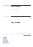
SMS045 - DSP Systems in Practice
Lab 3 - DSP Hardware Limitations
Due date: Friday Nov 21, 2003
Lab Purpose
This lab will focus on some of the design limitations that typically arise when implementing
real-time signal processing on a digital signal processor.
Preparations
• Read through the lab instructions carefully.
Required Hand-ins
Hand in one report per group, consisting of the following:
• An introductory paragraph that summarizes what you have done in the lab (about 1/2 A4
page).
• Assignment 1: Answer the following questions:
– What is, theoretically, the maximum number of instructions that can be done per
sample, when fs = 22.05 kHz?
– Approximately, how many ’dummy’ instructions per sample can be done without any
loss of sound quality?
– What happens when too many ’dummy’ instructions per sample are done? Try to
explain.
– Explain the difference between your result and the theoretical maximum number of
instructions per sample.
Include the assembler code used to implement the ’dummy’ instructions.
• Assignment 2: Plot the coefficients to your FIR low-pass filter before and after scaling.
Also, plot the relative round-off error for the coefficients before and after scaling. Include
the MATLAB code used to design the FIR low-pass filter, and the assembler code to your
filter implementation with the MAC overflow detection.
• Assignment 3: Plot the filter coefficients after improved scaling, and the relative round-off
error for the filter coefficients after improved scaling. Include the MATLAB code used to
find the appropriate coefficient scaling factor, and the assembler code for the implemented
MAC result shifting.
• Your oppinions about the lab and the lab instructions. Too easy? Too difficult? Suggestions
on changes.
Required Presentations
• Assignment 1: Demonstrate the result of your instruction rate test to the lab instructor.
• Assignment 2: Demonstrate your implemented FIR filter with the scaled coefficients and
the MAC overflow detection to the lab instructor.
• Assignment 3: Demonstrate your implemented FIR filter with the improved filter coefficient scaling to the lab instructor.
Include your names and email addresses on the titlepage of the report. Begin included assembler
code with comments that show your names and an explanation of what the code does. This could
for example look like:
// Robert Plant E3, Ron Wood D4
//
// Lab 3, Assignment 1.
// Code for testing the instruction rate limitations of the ADSP-2181.
Lab 3 - DSP Hardware Limitations
A ’Runthrough’ DSP Program
The DSP program that will be used as a base for the assignments in this lab, is the ’Runthrough’
program that can be downloaded from the course webpage. The program consists of a source file,
’Runthrough.asm’, a header file, ’def2181.h’, and a linker definition file, ’ADSP-2181.ldf’. The
program flow of the source file is shown in Figure 1.
(Program start)
SPORT0 setup
(ADC interrupt)
AD1847 codec setup
PSfrag replacements
Send output
samples to DAC
No
New
samples?
Get new input
sample from ADC
Yes
main loop
AX0=Input Sample L
AY0=Input Sample R
(RTI)
Output Sample L=AX0
Output Sample R=AY0
Figure 1: Program flow of the ’Runthrough’ program.
The program starts with initializations of the DSP’s serial port and the AD1847 codec, after
which the program enters an infinite loop, labeled ’main loop’. In this loop, the program continuously checks for new input samples from the ADC, by testing the state of a flag called
’New Samples’. Once this flag goes high, new input samples have been stored in the two variables
3
25th November 2003
Lab 3 - DSP Hardware Limitations
’Input Sample L’ (left input sample) and ’Input Sample R’ (right input sample). As seen in Figure 1, the input samples are simply copied to the output sample variables Output Sample L’ (left
output sample) and ’Output Sample R’ (right output sample). The output samples are sent to
the DAC upon the next interrupt from the codec. Thus, the output signal will be equal to the
input signal (i.e. the signals simply ’run through’ the DSP).
The ’Runthrough’ program can be used as a base for many different DSP applications. For
example, a FIR filter can be implemented by processing the input samples in a filter routine, and
then storing the filter output in the output sample variables.
Instruction Rate Limitations
One of the key features of a DSP (and any other processor), is the number of instructions the
processor can perform per time unit. The number of instructions per second that can be done,
is often referred to as the instruction rate, and is normally (for fixed-point processors) measured
in MIPS (millions of instructions per second). The importance of the instruction rate is best
described with an example.
In Figure 2, a timing diagram of a DSP process is shown on a time axis. This process applies
an FIR filter on incoming samples from the left and right stereo channels of an analog-to-digital
converter (ADC). Each time the ADC sends two new samples to the DSP, a ’Codec interrupt’
is generated, and the interrupt service routine (ISR) for the codec starts. The ISR stores the
incoming samples in some variable, and send the most recently calculated output samples to the
digital-to-analog converter (DAC). The ISR will always exexute just after the interrupt occurs;
any other operation that is currently ongoing will be stalled until the ISR finishes.
PSfrag replacements
Codec interrupt
: Codec ISR
Codec interrupt
FIR L
FIR R
FIR L
FIR R
t (sec)
1
fs
Figure 2: Timing diagram of a DSP FIR filter process.
After the ISR finishes, the left and right samples are filtered in two consecutive FIR routines
(’FIR L’ and ’FIR R’ respectively). Note from Figure 2 that the FIR routines finish well before
the next codec interrupt occurs. The codec interrupts will occur periodically with a period of
1/fs seconds, where fs is the sampling frequency in Hz.
Another situation is shown in Figure 3. The same FIR routines as in the previous example are
applied to the input samples. Only here, the sampling frequency is higher. This causes the
interrupts to occur at a higher rate than in the previous example. As seen in Figure 3, the time
25th November 2003
4
Lab 3 - DSP Hardware Limitations
PSfrag replacements
Codec interrupt
: Codec ISR
Codec interrupt
FIR L
F...
FIR L
F...
t (sec)
1
fs
Figure 3: Timing diagram of a DSP FIR filter process violating the real-time system constraints.
between interrupts, 1/fs , is now to short for these FIR routines. The FIR routine for the right
sample will not finish before the next codec interrupt occurs, and the right output sample will
probably be lost. Using real-time systems terminology, the real-time system constraints of the
program are violated.
A rough estimate of the number of instructions that can be performed on each sample can
be obtained by comparing the instruction rate of the DSP with the sampling frequency of the
ADC/DAC. Let us assume that the sampling frequency, f s , for a certain program is set to 22.05
kHz. The program runs on the ADSP-2181 processor, which has an instruction rate, R, of about
33 MIPS. The time between two consecutive codec interrupts is
1
≈ 0.045 msec.
fs
The maximum number of instructions per sample is therefore
1
R ≈ 1496 instructions.
fs
This is, as pointed out earlier, only a rough estimate, since the instruction rate, R, of the DSP
depends on how the instructions are actually implemented. Some operations can be implemented
in more than one way. For example, the following operations:
AR = AX0 + AY0;
AX0 = DM(I0,M0);
adds the contents of AX0 and AY0 and then loads AX0 with a new value. This can also be
implemented more efficiently by using a multifunction instruction:
AR = AX0 + AY0, AX0 = DM(I0,M0);
Here, both operations are done in a single line of code, using only one instruction. Hence, if
many instructions have do be done per sample (e.g. in a long filter), multifunction instructions
will provide more efficient programs, allowing for longer filters etc. Only certain operations may
be done using multifunction instrcutions. Refer to the ADSP-2100 Family User’s Manual for
detailed information.
5
25th November 2003
Lab 3 - DSP Hardware Limitations
Assignment 1 - Investigating Instruction Rate Limitations
In this assignment, the instruction rate limitations of the ADSP-2181 will be studied.
A simple way to test how many instructions can be done per sample, is to modify the ’Runthrough’
program, so that a known number of instructions are executed between every codec interrupt.
Referring to the timing diagram in Figure 2, the FIR filter routines in the figure can be simulated
by executing a large number of ’dummy’ instructions in the main loop, just after the input samples
have been stored in AX0 and AY0.
AX0 = DM(Input_Sample_L);
AY0 = DM(Input_Sample_R);
//******************************
// Process samples here
//******************************
DM(Output_Sample_L) = AX0;
DM(Output_Sample_R) = AY0;
The easiest way to do ’dummy’ instructions is to use a ’DO UNTIL’ loop with a ’nop’ (no operation)
instruction.
Do the following:
1. Download the three ’Runthrough’-program files from the course webpage (’Runthrough.asm’,
’def2181.h’, and ’ADSP-2181.ldf’). Also download the ’buckley.wav’ file.
2. Create a new VDSP project called ’IRtest’, using the ’Runthrough’ files.
3. Modify ’Runthrough.asm’ by adding a fixed number of ’dummy’ instructions (e.g. 1000) as
described above.
4. Set the sampling frequency of the codec to 22.05 kHz.
5. Build (and debug?) the program.
6. Play the ’buckley.wav’ file and listen to the DSP output signal in your headphones.
7. Try different amounts of ’dummy’ instructions to determine (approximately) the maximum
number of instructions that can be done per sample.
8. Demonstrate your results to the lab instructor.
25th November 2003
6
Lab 3 - DSP Hardware Limitations
Coefficent Quantization Issues
In Lab 1, the effects of coefficient quantization where studied by quantizing coefficients to a bandpass filter using MATLAB. Apart from the fact that an IIR filter may become unstable due to
quantizing, in general, a loss of numerical precision will often occur. When converting double
precision, floating point numbers (e.g. filter coefficients generated in MATLAB) to fixed point
representation for implementation in a DSP, some rounding of the numbers is always involved.
As an example, consider an FIR low-pass filter of order N = 64, designed in MATLAB using the
’fir1’ command. The coefficients for the filter are plotted in Figure 4. Using the approximated
0.2
Magnitude
0.15
0.1
0.05
0
0
10
20
30
Coefficient
40
50
60
Figure 4: The coefficients of an FIR low-pass filter of order N = 64.
quantization method described in Lab 1, the coefficients of this filter can be quantized to 16-bit
representation. The relative round-off error, ROi , for a coeffient bi can be determined by dividing
the difference between the quantized coefficent, bq i , and bi , by the magnitude of bi :
(bi − bqi )2
ROi = PN
.
2
i=0 bi
The relative round-off error for the coefficients in Figure 4 are plotted in Figure 5.
Filter Coefficient Scaling
Loss of numerical precision, due to filter coefficient quantization, can be remedied by scaling
the generated filter coefficients in MATLAB, so that the value of biggest coefficient is close (but
not equal) to one. Recall that the 1.15 fractional number format, used by the ADSP-2181, can
7
25th November 2003
Lab 3 - DSP Hardware Limitations
−9
1.2
x 10
Relative round−off error
1
0.8
0.6
0.4
0.2
0
0
10
20
30
Coefficient
40
50
60
Figure 5: The relative round-off error for the 16-bit quantized coefficients of an FIR low-pass
filter of order N = 64.
represent numbers between −1 and 1 − 2 −15 . Thus, if the filter coefficients are scaled so that they
are as big as allowed by the 1.15 format, a minimal relative round-off error may be obtained.
By scaling the filter coefficients shown in Figure 4, so that the magnitude of the greatest coefficient
is 0.99, the relative error shown in Figure 6 is obtained. Clearly, the overall relative error has
decreased. However, if done without care, coefficient scaling may actually decrease performance
of an implemented digital filter severely.
Computational Overflow
While scaling of coefficients allow for better numerical precision when converting floating point
numbers to fixed point representation, it will most likely make the implemented digital filter more sensitive to computational overflow. Overflow occurs when, for example, the multiplier/accumulator (MAC) of the DSP generates a result which magnitude is too big to be represented in the number format used. In an audio application, overflow will introduce distortion in
the DSP output signal.
For example, consider a convolution of an FIR filter of order N with coefficients b i with an input
signal, x[n], producing an output signal y[n],
y[n] =
N
X
x[n − i]bi .
i=0
25th November 2003
8
(1)
Lab 3 - DSP Hardware Limitations
−9
1.2
x 10
Relative round−off error
1
0.8
0.6
0.4
0.2
0
0
10
20
30
Coefficient
40
50
60
Figure 6: The relative round-off error for the scaled 16-bit quantized coefficients of an FIR lowpass filter of order N = 64.
This operation can be implemented in the ADSP-2181 by using multiply/accumulate instructions,
such as
MR = MR + MX0 * MY0 (SS);
Since both MX0 and MY0 must have magnitudes less than, or equal to one, the result of the
multiplication, MX0 * MY0, will never have a magnitude outside the 1.15 number range. The
accumulation, however, may cause the MAC result to overflow under certain conditions. For an
FIR filter generated with the ’fir1’ command in MATLAB, the coefficents are automatically
normalized so that the pass-band gain of the filter is equal to one. For a low-pass filter, this
implies that the sum of the coefficients, b i , is equal to one:
N
X
bi = 1.
(2)
i=0
If these coefficients are quantized to 1.15 fractional format and used in an FIR filter implementation on the ADSP-2181, the MAC result will only overflow under conditions where the magnitude
of the input signal to the ADC is very big.
Assignment 2 - Scaling of Filter Coefficients and Detecting MAC Overflow
In this assignment, a low-pass FIR filter will be implemented. Then, the coefficients will be
9
25th November 2003
Lab 3 - DSP Hardware Limitations
scaled, and the effects of scaling will be studied. A useful way of detecting MAC overflow during
code development will also be introduced.
1. Use the ’fir1’ command in MATLAB to design a FIR low-pass filter of order N = 128,
with a cut-off frequency fc = 2.2 kHz, at a sampling frequency fs = 22.05 kHz.
2. Use the ’dvec2hvec’ command to convert the filter coefficients to 1.15 fractional format.
3. Create a new VDSP project called ’Scaling’, based on the ’Runthrough’ files.
4. Implement your MATLAB-designed FIR low-pass filter.
5. Use the assembler instruction
IF MV SET FL1;
at the end of your filter convolution loops. This instruction will test the MAC status flag
MV, and turn on the LED on the EZ-KIT Lite board if the test result is true. The MV flag
is set whenever a MAC operation results in an overflow. By inserting the instruction
RESET FL1;
under the irqeisr: label (near the end of ’Runthrough.asm’), pressing the button marked
INTERRUPT on the EZ-KIT Lite board will turn of the LED.
6. Try your filter with the ’buckley.wav’ file. Adjust the volume of the PC sound card so that
the sound output from the DSP is zero.
7. Slowly increase the sound card output volume until the DSP sound output clips (becomes
distorted). This is caused by a MAC overflow, and should light the LED on the EZ-KIT
Lite board.
8. Try to find the maximum sound card output volume that can be achieved without MAC
overflow.
9. Scale your filter coefficients in MATLAB, so that the magnitude of the greatest filter coefficient is 0.99. Convert them to 1.15 format.
10. Replace our original filter coefficients with the scaled ones, and test your filter again.
11. Compare the sensitivity to MAC overflow between the scaled and the original coefficients.
12. Demonstrate your results to the lab instructor.
25th November 2003
10
Lab 3 - DSP Hardware Limitations
Improved Filter Coefficient Scaling
The previous assignment highlighted the fact, that although scaling of filter coefficients may
increase numerical precision, it will most likely make the digital filter sensitive to computational
overflow. In order to avoid this problem, the function of the MAC result register must first be
studied more closely.
Recall that the MAC result register, MR, is 40 bits wide. It is divided into two 16-bit registers, MR0
ag replacements
and MR1, and an eight bit register, MR2. Under normal operating conditions (when the magnitude
of the MAC result is not greater than one) the 32-bit result of a multiplication/accumulation
will be contained in MR0 and MR1. A rounded 16-bit result can then be taken from MR1 (most
significant bits of result).
As an example, consider a multiplication between the numbers 0.9 and 0.8. This would yield the
result 0.72, which has a magnitude less than one, and will not cause a MAC overflow. Figure 7
shows this result in binary form, as it would appear in MR. Notice from Figure 7 that all the bits
in MR2 are zero, which, in this case, confirms that the entire MAC result is represented by MR1
and MR0.
ag replacements
16 15
0
32 31
Bit # 39
0 0 0 0 0 0 0 0 0 1 0 1 1 1 0 0 0 0 1 0 1 0 0 0 0 1 1 1 0 0 0 0 1 0 1 0 0 1 0 0
MR2
MR0
MR1
Figure 7: The contents of the MAC result register when no overflow has occurred (MR = 0.72).
Continuing with our example, suppose that the previous result, 0.72, is added to the result of a
new multiplication between 0.5 and 0.6. This yields the result 1.02. Figure 8 shows the contents
of MR after this operation.
Bit #
32 31
39
16 15
0
0 0 0 0 0 0 0 0 1 0 0 0 0 0 1 0 1 0 0 0 1 1 1 0 0 1 1 1 0 0 0 0 1 0 1 0 0 1 0 0
MR2
MR0
MR1
Figure 8: The contents of the MAC result register when an overflow has occurred (MR = 1.02).
Even here, all the bits in MR2 are zero, but the most significant bit of MR1 is one, indicating
that the value of MR1 is negative. If the contents of MR1 is now used as the rounded result of
the multiplication/accumulation, this would give the erroneous result -0.98. The last multiplication/accumulation causes the MAC result to overflow into the guard bits in MR2. This sets the
MAC status flag, MV, to indicate that an overflow has occurred.
Downscaling of MAC Result
In the example above, the result of the MAC operation 0.9 ∗ 0.8 + 0.6 ∗ 0.5 = 1.02 generated a
result that was too big to be represented by a 16-bit number. Any MAC result with a magnitude
11
25th November 2003
Lab 3 - DSP Hardware Limitations
greater than one will have to use part of MR2 to represent the result. Suppose that a MAC
operation yields a result with magnitude M > 1. If 2 k−1 < M < 2k for some positive integer k,
the k least significant bits of MR2 will contain relevant result bits. For example, if the MAC result
is -2.7, the two least significant bits of MR2 contain relevant result bits.
With this knowledge, the guard bits in MR can actually allow MAC results of magnitude greater
than one to overflow into MR2, under the assumption that it is known beforehand how many bits
of MR2 that belong to the true result. If the number of used guard bits is k, the barrel shifter of
the ADSP-2181 can be used to shift the contents of MR down by k bits. Refer to the ADSP-2100
Family User’s Manual for detailed information about the barrel shifter.
The following code will shift the contents of MR2 and MR1 down one bit, add them using an OR
instruction, and store the result in the AR register.
SI = MR2;
SR = LSHIFT SI BY -1 (HI);
AX0 = SR0;
SI = MR1;
SR = LSHIFT SI BY -1 (LO);
AY0 = SR0;
AR = AX0 OR AY0;
After the shifting operations above, AR will, in this case, contain the correct MAC result, multiplied by 2−1 . In the example above, the result will be 1.02 ∗ 2 −1 = 0.51. In general, shifting down
a binary number k bits is the same as multiplying it by 2 −k .
An improved scaling of filter coefficients can therefore be done as follows:
• Multiply the filter coefficients generated by MATLAB with the greatest number 2 k , such
that the magnitude of the greatest coefficient is as close to one as possible (without being
equal to, or greater than one).
• Implement a logical down-shift of the MAC result by k bits, after each filter convolution
loop in the DSP filter program.
Using this method, numerical precision is increased without making the digital filter more sensitive
to output signal distortion caused by MAC overflow. Since the filter output is scaled by 2 −k , the
net pass-band gain of the filter will be equal to one.
Assignment 3 - Improved Scaling of Filter Coefficients
In this assignment, the improved filter coefficient scaling described above will be implemented on
the low-pass filter designed in the previous assignment.
25th November 2003
12
Lab 3 - DSP Hardware Limitations
1. Use the strategy outlined above to scale the original (non-scaled) coefficients of your FIR
low-pass filter by a factor 2k .
2. Create a new VDSP project called ’Improved Scaling’, based on the ’Scaling’ project from
the previous assignment.
3. Implement a logical down-shift of the MAC results from your filter convolution loops by k
bits, as described above.
4. Try your filter with the new scaled coefficients, using the ’buckley.wav’ file.
5. Investigate the filter’s sensitivity to MAC overflow by observing the LED, and adjusting
the sound card output volume.
6. Demonstrate your results to the lab instructor.
13
25th November 2003