1
Installation and User Guide
Auto-CrushIRTM
Programmable Hydraulic Press
The information in this publication is provided for reference only. All
information contained in this publication is believed to be correct and
complete. PIKE Technologies, Inc. shall not be liable for errors contained herein
nor for incidental or consequential damages in connection with the furnishing,
performance, or use of this material. All product specifications, as well as the
information contained in this publication, are subject to change without notice.
This publication may contain or reference information and products protected
by copyrights or patents and does not convey any license under the patent
rights of PIKE Technologies, Inc. nor the rights of others. PIKE Technologies, Inc.
does not assume any liability arising out of any infringements of patents or
other rights of third parties.
This document contains confidential or proprietary information of PIKE
Technologies, Inc. Neither this document nor the information herein is to be
reproduced, distributed, used or disclosed, either in whole or in part, except as
specifically authorized by PIKE Technologies, Inc.
PIKE Technologies, Inc. makes no warranty of any kind with regard to this
material including, but not limited to, the implied warranties of merchantability
and fitness for a particular purpose.
Copyright 1991-2011 by PIKE Technologies, Inc., Madison, WI 53719. Printed in
the United States of America. All world rights reserved. No part of this
publication may be stored in a retrieval system, transmitted, or reproduced in
any way, including but not limited to, photocopy, photograph, magnetic or
other record, without the prior written permission of PIKE Technologies, Inc.
Address Comments to:
PIKE Technologies, Inc.
6125 Cottonwood Drive
Madison, WI 53719
Phone
Fax
E-mail
Web Site
Jan. 1, 2011
(608) 274-2721
(608) 274-0103
[email protected]
www.piketech.com
Contents
Introduction
Basic Operation Diagram
Unpacking Your Accessory
Packing List
Installation
Using Your Hydraulic Press
Manual Mode
Automatic Mode
Precautions
Maximum Force
Transporting/Moving Hydraulic Press
Operation
Safety
Environmental Ratings
Cleaning Procedures
Equipment Voltage Ratings
Power Supply Symbol Definitions
Special Handling Requirements for KBr Powder
Replacement Parts and Options
1
1
2
2
3
3
4
5
8
8
8
8
8
9
9
9
10
10
11
Introduction
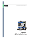
The Auto-CrushIR™ is a 15 US ton (13.6 metric ton) programmable hydraulic press ideal for making
KBr transmission pellet samples such as KBr pellets and thin films with heated platens for FTIR analysis.
With its digital pressure reading, the Auto-CrushIR™ provides excellent reproducibility and efficient
operation. Using the touch screen, the hydraulic press may be run in a manual mode or automatic
mode, which allows up to five steps to be programmed. Its adjustable open port design allows for easy
insertion and removal of the pellet press and heated platens.
The PIKE Auto-CrushIR includes a transparent protective shield making it safe for operation in a busy
laboratory environment. Access for vacuum hose and other utilities is made through a port in the rear
of the press. The adjustable die stop provides flexibility for die designs of short and long dimensions
yielding an open stand range from 2 to 4.5 inches (5 to 11.5 cm). The efficient-sized ram stroke of 0.22
inches (5.6 mm) and adjustable die stop screw speeds up pellet making by minimizing the time required
to achieve the desired force.
All mechanical components of the press are enclosed in a metal cabinet. The access area is protected by
a high-impact polymer shield.
Adjustable Die Stop
Hydraulic Fluid Release Nut
Touch Screen
Packing Bolts
Protective Shield
Figure 1: Front view of the Auto-CrushIR Programmable Hydraulic Press
PN 350-1811300-01
P a g e |1
Unpacking Your Accessory
In order for you to quickly verify receipt of your accessory, we have included a packing list. Please
inspect the contents of the shipping box carefully. Contact PIKE immediately if any discrepancies are
found.
The Auto-CrushIR is packed in a wooden shipping box. Remove screws from the box to take off the cover
of the shipping box. Remove the 4 packing bolts located at the corners of the Auto-CrushIR base plate.
Lift the Auto-CrushIR and put it into place where it will be used to make pellets.
CAUTION: The Auto-CrushIR is heavy, weighing 90 lb., 36.3 kg. Obtain help to lift and
move the Auto-CrushIR Programmable Hydraulic Press.
Packing List
Auto-CrushIR Manual
Auto-CrushIR
Power Cord
PN 350-1811300
PN 181-1300
Quantity 1
Quantity 1
Quantity 1
3/16” Allen Hex Wrench
Fuse
PN 410-0058
Quantity 2
Quantity 1
PN 615-001800p
PN 350-1811300-01
P a g e |2
Installation
Using the 3/16” allen hex wrench, fully loosen the hydraulic fluid-retaining screw located at the right,
upper side of the Auto-CrushIR.
NOTE: The Auto-CrushIR will not function unless this screw is loosened. Always close the fluidretaining screw to transport or tilt the Auto-CrushIR.
The Auto-CrushIR is available in a 115 or 220 V version. Install the power cord into the rear of the
Auto-CrushIR programmable hydraulic press. Turn the power switch located on the back of the press to
the on position. Figure 2 shows the home screen that is displayed upon powering up the press. The
digital display will read 00.0 when no force is applied.
The force reading on the Auto-CrushIR digital display is shown in units of US tons.
Figure 2: Home screen of the Auto-CrushIR Programmable Hydraulic Press (units in US tons)
PN 350-1811300-01
P a g e |3
Using Your Hydraulic Press
Place your pellet press into the Auto-CrushIR adjusting the die stop as needed to provide a comfortable
amount of clearance. Position the pellet press so that it’s top and bottom are centered relative to the
die stop and the hydraulic ram. Close the protective shield. There is a safety switch, which is engaged
when the protective shield is closed. The Auto-CrushIR will not operate while the shield is in the up
position.
From the home screen the mode of operation may be selected as either manual or automatic. If the
touch screen display is not on the home screen, press the RETURN button on the screen until the home
screen appears.
Caution: Be sure the pellet press is centered on the bottom ram and the adjustable die stop is
screwed firmly against the top of the pellet press. Failure to properly set the adjustable die
stop against the object to which force is being applied will cause a malfunction.
Manual Mode
The manual mode of operation allows the user to set and release a load. Select the manual mode by
pressing the MANUAL button from the home screen. To operate, continue pressing the INC (increase)
button until the desired force is obtained. To stop increasing the force, remove the touch pressure to
the INC button. The hydraulic pump will automatically shut off if the INC button is held on for longer
than 8 seconds. If after 8 seconds the desired force is not achieved, release the INC button and repress
to continue increasing the applied force. The force will hold until the REL (release) button is touched.
WARNING: In the case of the PIKE Evacuable Pellet Press and the PIKE Heated Platens Accessory, the
maximum force is 10 US tons. Never exceed the maximum force rating of the pellet press.
NOTE: KBr powder is soft and compressible. When maximum force is applied to the powder it is normal
for the digital reading to drop initially before it settles and reaches a steady-state reading.
Be sure the pellet press is centered on the bottom ram and the adjustable die stop is screwed firmly
against the top of the pellet press prior to operating the press in manual or automatic mode. Failure to
properly set the adjustable die stop against the object to which force is being applied will cause a
malfunction. Please see the precaution section of this manual for additional details.
PN 350-1811300-01
P a g e |4
Figure 3: Manual mode screen
Automatic Mode
The automatic mode allows the user to program up to five force-time steps. Select the automatic mode
by pressing the automatic button from the home screen. Figure 4 shows the screen listing the
programmed parameters, steps 1 – 5. The force and hold time duration is shown.
Figure 4: Automatic programmed parameters
PN 350-1811300-01
P a g e |5
To alter the existing program, touch the Change button. A screen to edit step 1 of 5 will be shown
(Figure 5). Select the pressure by touching and holding either the INC (increase) or DEC (decrease)
button. Repeat the procedure for the hold time.
To advance to step 2 of the program select NEXT and follow the instructions described above to select
the pressure and hold times. If less than five steps are required set the unneeded steps at a final
pressure value of zero. When a relaxation time is required, as shown in step 4 of the example shown in
Figure 4, set the final pressure to zero and the hold time equal to the relaxation time.
Touch the RETURN button when the program edits are complete, which will return you to the Automatic
page listing the program parameters (Figure 4). Press the start button to implement the program. Be
sure the pellet press is centered on the bottom ram and the adjustable die stop is screwed firmly against
the top of the pellet press. Failure to properly set the adjustable die stop against the object to which
force is being applied will cause a malfunction.
Figure 5: Automatic mode edit screens for step 1 and 2
While the program is running, the five steps are shown on the touch screen (Figure 6). The active step is
highlighted in green. When the program steps have been fully executed press the return button to
return to the tabular program screen and access the start button. To stop the automatic program at any
time during a run, touch CANCEL.
PN 350-1811300-01
P a g e |6
Figure 6: Screen shown during an automated run (A) and after the run is completed (B)
PN 350-1811300-01
P a g e |7
Precautions
Maximum Force
The Auto-CrushIR can deliver up to 15 tons of force. Do not exceed the maximum force
rating of the pellet press. For example, the PIKE Evacuable Pellet Press has a maximum
force rating of 10 tons. Carefully review the user manual for your pellet press to find its
maximum force rating. Exceeding the maximum force rating will result in damage to the
pellet press.
Transporting/Moving Hydraulic Press
The fluid-retaining screw must be released before using the Auto-CrushIR (see page 5). The fluidretaining screw must be secured (closed) if you transport the Auto-CrushIR or if you need to tilt it or lay
it on its side. Failure to follow these procedures will result in non-operation and/or leaking of fluid.
Operation
Be sure the pellet press is centered on the bottom ram and the adjustable die stop is screwed firmly
against the top of the pellet press. Failure to properly set the adjustable die stop against the object to
which force is being applied will cause the moveable lower ram to become lodged in the fully up
position. If this should happen the hydraulic pump will shut off.
To reposition the lower ram, put a metal piece to act as a spacer between the lower ram and the
adjustable die screw. In the manual mode press and hold the REL button in 3 second cycles while turning
the adjustable die stop clockwise with the provided 5/16” hex wrench.
Safety
Always close the transparent protective shield before applying force to the pellet press.
Failure to follow this procedure could result in physical injury to the operator. Additionally,
the protective shield in the down position triggers a safety switch to allow Auto-CrushIR
operation. When the shield is in the up position the Auto-CrushIR touch panel is disabled
and the press will not operate. Protection provided by the equipment may be impaired if
the equipment is used with accessories not provided or recommended by the manufacturer,
or is used in a manner not specified by the manufacturer.
Periodically inspect the external power cord, transparent protective shield, and other parts for damage.
If any damage is observed, do not use the equipment and contact PIKE Technologies for replacement
parts.
Do not position the equipment in a space where it is difficult to disconnect the power cord at the rear of
the equipment.
PN 350-1811300-01
P a g e |8
Environmental Ratings
Installation Category II:
Pollution Degree 2:
Altitude Limit:
Usage:
Ambient Temperature:
Humidity:
(Transient Over-voltage)
(Temporary conductivity caused by condensation)
2,000 meters
Indoor
40 °C max
80% RH non-condensing
Cleaning Procedures
Clean the Auto-CrushIR Hydraulic Press using a cloth dampened with water.
Clean the Pellet Press and any residual KBr powder using water. Dry thoroughly after cleaning.
Decontamination not required.
Equipment Voltage Ratings
External Power Required:
115VAC (not selectable – preset at the factory)
50/60 Hz, 13 Amps max
Use grounded, three prong plug
Fuse input with 8A@250V Time Lag
Do not remove covers. Refer servicing to qualified personnel.
PN 350-1811300-01
P a g e |9
Power Supply Symbol Definitions
DC direct current:
AC alternating current:
Equipment protected throughout by double or reinforced insulation:
Special Handling Requirements for KBr Powder
Read and follow the MSDS sheet recommendations for the KBr powder prior to use. Observe all safety
precautions and procedures while handling the KBr powder and finished pressed pellets. Follow MSDS
recommended clean-up, spill procedures for the KBr powder.
Label
PN 350-1811300-01
Description
Location
CE marking indicates the accessory complies with the
essential requirements of the relevant European health,
safety and environmental protection legislations.
This symbol is located
on the backside of the
hydraulic press
accessory.
The crossed out wheeled bin is a clear reminder that the
product must not be disposed with household waste. It is
the responsibility of the buyer to discard the product in
accordance with federal, regional, and local
environmental regulations.
This symbol is located
on the backside of the
hydraulic press
accessory.
The RoHS symbol indicates this product is free from
RoHS prohibited elements and compounds (Pb, Cd, Hg,
Hex-Cr, PBB, and PBDE).
This symbol is located
on the backside of the
hydraulic press
accessory.
This label indicates power consumption information.
This symbol is located
on the backside of the
hydraulic press
accessory.
P a g e | 10
Replacement Parts and Options
The following parts and options may be ordered for the Auto-CrushIR accessory:
Part Number
410-0058
Description
3/16” Allen Wrench
Other PIKE products available for use with the Hydraulic Press:
160-8010
161-1900
161-1070
161-5050
181-2000
076-1220
162-5300
162-5410
KBr Powder 100g
13 mm Pellet Press Die Kit
ShakIR, Heavy Duty Sample Grinder
Agate Mortar and Pestle, 50 mm
PIKE Heated Platens Accessory
Digital Temperature Control Module (required for Heated Platens)
Magnetic Pellet Holder
Sample Card – for 13 mm Pellets (10)
PN 350-1811300-01
P a g e | 11
6125 Cottonwood Drive · Madison, WI 53719-5120 · (608) 274-2721 (TEL) · (608) 274-0103 (FAX)
[email protected] · www.piketech.com