1
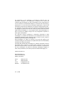
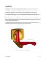
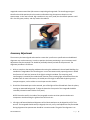
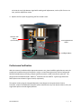
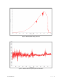
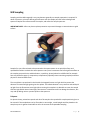
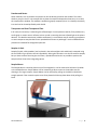
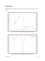
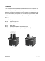
Installation and User Guide
IntegratIRTM NIR Integrating Sphere
The information in this publication is provided for reference only. All
information contained in this publication is believed to be correct and
complete. PIKE Technologies, Inc. shall not be liable for errors contained herein
nor for incidental or consequential damages in connection with the furnishing,
performance, or use of this material. All product specifications, as well as the
information contained in this publication, are subject to change without notice.
This publication may contain or reference information and products protected
by copyrights or patents and does not convey any license under the patent
rights of PIKE Technologies, Inc. nor the rights of others. PIKE Technologies, Inc.
does not assume any liability arising out of any infringements of patents or
other rights of third parties.
This document contains confidential or proprietary information of PIKE
Technologies, Inc. Neither this document nor the information herein is to be
reproduced, distributed, used or disclosed, either in whole or in part, except as
specifically authorized by PIKE Technologies, Inc.
PIKE Technologies, Inc. makes no warranty of any kind with regard to this
material including, but not limited to, the implied warranties of merchantability
and fitness for a particular purpose.
Copyright 1991-2016 by PIKE Technologies, Inc., Madison, WI 53719. Printed in
the United States of America. All world rights reserved. No part of this
publication may be stored in a retrieval system, transmitted, or reproduced in
any way, including but not limited to, photocopy, photograph, magnetic or
other record, without the prior written permission of PIKE Technologies, Inc.
Address Comments to:
PIKE Technologies, Inc.
6125 Cottonwood Drive
Madison, WI 53719
Phone
Fax
E-mail
Web Site
Jan. 1, 2016
(608) 274-2721
(608) 274-0103
[email protected]
www.piketech.com
Contents
Introduction
Unpacking Your Accessory
Packing List
Installation
Spectrometer Settings
Accessory Adjustment
Performance Verification
NIR Sampling
Polymers
Powders and Pastes
Transparent and Semi-Transparent Films
Samples in Vials
Sample Mount
Typical Spectra
Precautions
Options
PN 350-048601-01
1
2
2
3
3
4
5
7
7
8
8
8
8
9
10
10
Introduction
IntegratIR™ series Near-Infrared Integrating Sphere module is a compact sampling accessory for
measuring the composition of a wide variety of solid and paste materials. Using near-infrared
chemometrics, qualitative product identification or quantitative analysis may be performed on
pharmaceutical, nutraceutical, chemical, polymer, textile, food, agricultural or other samples.
The IntegratIR module features a 2” high reflectivity gold coated integrating sphere and a high-speed,
low-noise Indium-Gallium-Arsenide detector with transfer optics and interface electronics. The
IntegratIR fits in the sample compartment of the FTIR spectrometer and connects to the external
detector port of the spectrometer. The 0.5” diameter borosilicate glass window serves as a sampling
port on the top of the integrating sphere. The window is bonded and sealed to protect the sphere from
corrosive materials and contamination.
The optical design of the NIR IntegratIR directs the beam through the bottom of the sphere at a nearnormal angle, and is focused at the sample position at the top of the sphere.
Figure 1. Optical diagram of the NIR IntegratIR
PN 350-048601-01
P a g e |1
Unpacking Your Accessory
In order for you to quickly verify receipt of your accessory, we have included a packing list. Please
inspect the package carefully.
Packing List
NIR IntegratIR User Manual
NIR IntegratIR Accessory
Diffuse Gold Reference
PN 350-048601
PN 048-60XX
PN 048-3000
Quantity 1
Quantity 1
Quantity 1
Light Shield
Vials
Vial Holder
Quantity 1
PN 048-2999
PN 044-3010
Quantity 1 Pack of 25
Quantity 1
Spoon, Camel Hair Brush, Spatula
Hex Wrenches
Quantity 1 Each
Quantity 1 Set
PN 350-048601-01
P a g e |2
Installation
Before installation, make sure the spectrometer is working in the near-infrared region without the
IntegratIR. Please consult the manufacturer of the FT-IR spectrometer regarding the conversion of the
bench to near-infrared. This may involve replacing the beam splitter and source to optimize for the
10,000 to 4000 cm-1 wavelength region of the IntegratIR. It is advisable to perform an alignment of the
interferometer before inserting the IntegratIR into the sample compartment.
Each IntegratIR unit is custom manufactured to interface with a specific model FTIR Spectrometer.
Operation with a different model may require a factory conversion to be done by PIKE Technologies.
Place the accessory in the sample compartment of the spectrometer. The baseplate of the accessory
assures the alignment of the accessory relative to the beam coming from the spectrometer. A captive
thumb screw on the baseplate of the IntegratIR attaches the accessory to the sample compartment
baseplate of the bench and prevents it from rotating from the nominal position. Connect the detector
cable to the spectrometer.
CAUTION: Make sure power to the spectrometer bench is off before connecting the
detector cable. For ThermoFisher instruments use the cable attached to the 15 pin D
connector in the sample compartment of the spectrometer. Select the appropriate source,
optical path and detector. Please consult the software manual provided by the spectrometer
manufacturer concerning how to perform the detector and source selection.
To connect the IntegratIR, please turn off the spectrometer. After the accessory detector cable is
connected to the instrument and the accessory, power up the instrument.
Spectrometer Settings
Set the collection parameters as follows.
Wavelength Range
Velocity
Aperture
10,000 – 4000 cm-1
Select appropriate for InGaAs detector for your FTIR spectrometer
Appropriate J-stop
Resolution
4 or 8 cm-1
Scan Time
30-60 s
Place the Diffuse Gold Reference on the sample window to maximize the light level in the sphere. The
gain of the IntegratIR is set during manufacturing to allow the best signal-to-noise; however, the signal
PN 350-048601-01
P a g e |3
magnitude cannot exceed the A/D converter required signal magnitude. The interferogram signal
therefore should be optimized to the maximum allowable using the aperture selection on the
spectrometer. In the near-infrared, high resolution is very rarely used, thus the default aperture could
be in the fully open position, and may need to be reduced.
Accessory Adjustment
The accessory has been aligned and tested to ensure that it performs to specifications and additional
alignment may not be necessary. In order to optimize the beam positioning in your instrument small
adjustments may be required. This should be preferably done by trained service personnel. The
alignment procedure is as follows:
1. With no sample on the sampling window and covering the window with the enclosed Shielding Cap
establish the magnitude of the interferogram. In most instruments with proper alignment it should
be a fraction of a volt size, because all the light is exiting the window. The remaining small
interferogram is caused by the residual small fraction of the incoming light reflected back from the
window itself. On most instruments, the visible part of the light is observable by placing a semitransparent paper, such as vellum or scotch tape over the window.
2. Should the illuminated spot not be centered, part of the light will be reflected back from the sphere,
causing an unwanted background. To align the beam the front panel of the IntegratIR should be
removed (4 slotted screws hold the front panel).
NOTE: Please be careful, the inside of the IntegratIR contains sensitive optical and electronic
components. Avoid touching the gold surfaces of the mirrors.
3. Left-right and forward-backward alignment of the illuminated spot can be aligned by a 3/32” hex
wrench. The IntegratIR should come pre-aligned, thus only a very small adjustment may be needed.
During alignment the spectrometer should be in monitor mode. The goal of the alignment is to
PN 350-048601-01
P a g e |4
minimize the stray light detector signal while making small adjustments, such as 1/16 of a turn at a
time, with the adjustment screws.
4. Replace the front panel by tightening the four slotted screws.
Detector Gain
Adjust
(service only)
Forward/Backward
Adjust
Left/Right Adjust
Performance Verification
With the accessory installed and the appropriate aperture set, place the diffuse gold reference onto the
sample port located at the top of the sphere. Using a 1 minute data collect time, collect a background
followed immediately by collecting a sample spectrum to obtain a 100% transmission spectrum. The
peak to peak noise between 6200 – 6000 cm-1 should be less than 0.08 %T. Typical single beam and
100% spectrum are shown in Figures 2 and 3, respectively.
The spectral results using the IntegratIR depend to some degree on the spectrometer. Source
intensities, shape of the NIR beam, the beam splitter characteristics vary from bench to bench; thus, the
single beam spectra could be slightly different.
PN 350-048601-01
P a g e |5
Figure 2. NIR single beam energy spectrum
Figure 3. 100% transmission spectrum for noise evaluation
PN 350-048601-01
P a g e |6
NIR Sampling
Sampling with the NIR IntegratIR is very easy because generally no sample preparation is required. To
obtain a spectrum, place the diffuse gold reference over the sample port and collect a background
spectrum. Replace the reference with the sample, and collect the sample spectrum.
IMPORTANT NOTE: After use please replace protective cap to avoid damage or contamination to gold
surface.
Samples for near-infrared need to be presented to the spectrometer in an optically uniform and
reproducible fashion to obtain the same spectrum every time. Parameters that have significant effect on
the samples are particle size and distribution, crystallinity, phase (melted or solidified oils for example
have very different spectra), compression, temperature (especially water containing samples) and other
physical or chemical differences.
The round plastic cap enclosed in the kit with the IntegratIR serves as a light shield to protect the
detector from external light getting into the sphere. The InGaAs detector is very sensitive and could pick
up light from the fluorescent room light. When running thin samples it is advisable to cover the sample
with the Light Shield. Normal room light, fluorescent or incandescent will not damage the detector, but
may end up adding noise or spurious peaks to the spectrum.
Polymers
For plastic sheets, painted test panels and other flat samples the reproducible sample positioning has to
be assured. If the sample does not lay flat under its own weight, a small weight could be placed on the
sample to press it against the window to aid in the accurate and repeatable sampling.
PN 350-048601-01
P a g e |7
Powders and Pastes
Other materials, such as powders and pastes can also be directly placed on the window. The choice
whether you use a vial or a microscope slide to place the sample on depends on how easy it is to clean
the sample off the window. The window is sealed using epoxy compound, thus it is relatively chemically
inert and can be cleaned preferably with alcohol.
Transparent and Semi-Transparent Films
In all cases, the accessory is measuring the reflected light. For transparent materials, films produce very
small signal. In certain cases a reflective mirror can aid in returning the near-infrared light to the sphere
detector. This double transmission (called transflectance) is a convenient way of measuring transparent
or semi-transparent samples that have a reproducible thickness or pathlength. Use the Gold Reference
placed on the window for background spectrum.
Samples in Vials
Samples (liquids, solids, powders) can be placed in the enclosed glass vials and directly measured using
the vial holder ring to position the vial reproducibly. Other glass containers can also be used for samples,
but you have to assure that the glass is uniform, reproducible and as thin as possible to position the
sample surface close to the integrating sphere.
Sample Mount
The Sample Mount is the blue plate on top of the IntegratIR. It can be centered to hold the Vial Holder
or the Gold Reference. Sample Mount can be rotated to get direct access to the window area for
cleaning or for larger samples. Sample Mount can be removed by pulling on the black knurled knob
straight upward. If the removal requires more force please hold the top plate down while pulling the
knob.
PN 350-048601-01
P a g e |8
Typical Spectra
The NIR IntegratIR offers a simple method of measuring a wide range of samples. Example spectra are
shown.
Figure 4. NIR spectrum of polymer pellets collected using the NIR IntegratIR
Figure 5. NIR spectrum of aspirin powder collected using the NIR IntegratIR
PN 350-048601-01
P a g e |9
Precautions
In order to provide the maximum signal in the infrared, with the minimum spectral interference, the
mirrors used in this device are gold coated. Since the coatings are soft, care must be taken to avoid
damage. Normally, these mirrors will not need cleaning, since they are contained within the housing of
the accessory. If they do need cleaning, they may be gently wiped with a lint-free, abrasive-free cloth,
such as lens tissue, or with a camel hair brush. Under no circumstances must the mirrors be rubbed
with paper products such as “Kleenex” since this may produce scratching of the mirror coating.
Options
Part Number
Description
048-2999
048-3000
044-3010
048-0151
048-1050
048-3070
Sample Vials (Pack of 25)
Diffuse Gold Reference
21 mm Glass Vial Holder
Beaker Adapter
Rotating Sample Holder (for inhomogeneous sample)
Extended Range NIR Wavelength Standard (10,000-4000 cm-1)
Figure 6. NIR IntegratIR with Beaker Adapter
PN 350-048601-01
Figure 7. NIR IngetratIR with Rotating Sample Holder
P a g e | 10
6125 Cottonwood Drive · Madison, WI 53719-5120 · (608) 274-2721 (TEL) · (608) 274-0103 (FAX)
[email protected] · www.piketech.com