1
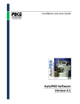
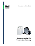
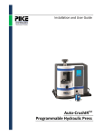
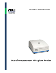
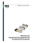
Installation and User Guide
AutoDiff TM Automated
Diffuse Reflectance Accessory
The information in this publication is provided for reference only. All
information contained in this publication is believed to be correct and
complete. PIKE Technologies, Inc. shall not be liable for errors contained herein
nor for incidental or consequential damages in connection with the furnishing,
performance, or use of this material. All product specifications, as well as the
information contained in this publication, are subject to change without notice.
This publication may contain or reference information and products protected
by copyrights or patents and does not convey any license under the patent
rights of PIKE Technologies, Inc. nor the rights of others. PIKE Technologies, Inc.
does not assume any liability arising out of any infringements of patents or
other rights of third parties.
This document contains confidential or proprietary information of PIKE
Technologies, Inc. Neither this document nor the information herein is to be
reproduced, distributed, used or disclosed, either in whole or in part, except as
specifically authorized by PIKE Technologies, Inc.
PIKE Technologies, Inc. makes no warranty of any kind with regard to this
material including, but not limited to, the implied warranties of merchantability
and fitness for a particular purpose.
Copyright 1991-2014 by PIKE Technologies, Inc., Madison, WI 53719. Printed in
the United States of America. All world rights reserved. No part of this
publication may be stored in a retrieval system, transmitted, or reproduced in
any way, including but not limited to, photocopy, photograph, magnetic or
other record, without the prior written permission of PIKE Technologies, Inc.
Address Comments to:
PIKE Technologies, Inc.
6125 Cottonwood Drive
Madison, WI 53719
Phone
Fax
E-mail
Web Site
Jan. 1, 2014
(608) 274-2721
(608) 274-0103
[email protected]
www.piketech.com
Contents
Introduction
Unpacking Your Accessory
Packing List
1
2
2
Optical Description
4
Installation
Loading the Sample Tray
5
6
Alignment
Installing the AutoPRO Motor Controller
7
9
Connecting the Motor Controller to Your
Computer
Correct Cabling Procedure
9
10
Installation of the AutoPRO Software
System Requirements
10
10
Loading from Windows
Files Placed on Your Hard Disk
Online Help
10
11
12
How to Use Help
12
AutoPRO Overview
13
AutoPRO Control
13
Status
15
Init.exe, First.exe…
15
Sample Preparation for the AutoDiff
16
Sample Cups
Preparing the Sample
16
16
Loading the Sample
17
Theory
18
Introduction
The PIKE Technologies AutoDiffTM is a high performance automated diffuse reflection accessory which is
available for most FTIR Spectrometers. The design employs a high efficiency fixed ellipsoidal mirror to
collect the maximum amount of diffusely reflected energy from the sample. Operating under program
control from within the FTIR software, the data generated may be processed either sequentially after
each scan or stored to disk for further analysis.
The sample holder contains positions for sixty samples. Also, in the center of the sample holder is a
position for a background sample. This background sample usually consists of pure KBr powder. The
sample holder is marked into 6 areas, labeled from A to F. Each area has 10 sample positions marked
from 1 through 10. The samples are moved automatically into position in the infrared beam by means of
the Motion Controller and AutoPROTM software. An R-Theta motion is used by the accessory for
positioning each sample.
Figure 1. AutoDiff accessory
PN 350-043001-02
P a g e |1
Unpacking Your Accessory
In order for you to quickly verify receipt of your accessory, we have included a packing list. Please
inspect the package carefully.
Packing List
AutoDiff Manual
AutoPRO Manual and Software
AutoDiff Accessory
PN 350-090000
PN 350-000070
PN 043-28XX
Quantity 1
Quantity 1
Quantity 1
60-Position Sample Tray
Sample Cups, large
Motor Controller
PN 042-2025
PN 043-3090
Quantity 1
Quantity 1
Quantity 60
USB Cable
15-Pin Male/Male Accessory
Cable
Power Cable
Quantity 1
Quantity 1
Quantity 1
PN 350-043001-02
P a g e |2
Packing List, continued
Sampling Preparation Kit
Purge Rings
Purge Kit
PN 042-3040
Quantity 8
Quantity 1
Quantity 1
Hex Wrench Set
Extra Fuses (2 amps each)
Quantity 1
Quantity 2
PN 350-043001-02
P a g e |3
Optical Description
The optical system of the AutoDiff is symmetrical with identical mirrors being used for the optical path
from the spectrometer interferometer to the sample and the sample to the spectrometer detector. Two
flat mirrors and an ellipsoidal mirror are used in each path.
The two lower mirrors are adjustable and are used for aligning the optical system at installation. The
upper flat mirrors and ellipsoid mirror are fixed in position. The ellipsoid is a large solid-angle monolithic
mirror which condenses the beam onto the sample with a power of 3 times. If the beam in your
spectrometer sample compartment with no accessory in place is 9 mm in diameter, the size of the
focused spot at the sample in the AutoDiff is 3 mm.
Note that the size of the beam in the spectrometer is dependent on manufacturer. Refer to your
spectrometer user guide for the correct size.
Figure 2. Optical path of the AutoDiff accessory
PN 350-043001-02
P a g e |4
Installation
Inspect the drawing below and locate the indicated items on your accessory.
Sample Cup
Sample Tray
Focus Adjust Knob
Purge Tube
Purge Fitting
Front Cover
Screws
Figure 3. Front view of the AutoDiff
To install the accessory in your sample compartment perform the following:
1. With the sample compartment of the spectrometer empty, scan a background with your FTIR
software and save to disk. This single beam spectrum can be used to verify the performance of the
system.
2. If your accessory is equipped with the instrument’s manufacturer standard baseplate, remove the
original sample compartment baseplate from the spectrometer. Place the accessory in the sample
compartment and secure it with screws used for baseplate attachment.
PN 350-043001-02
P a g e |5
3. If the accessory uses a sub-plate that attaches to the instrument’s original sample compartment
baseplate, remove the lower front cover of the accessory first. Place the AutoDiff in the sample
compartment of the spectrometer and position it on the baseplate pins. Find a captive thumbscrew
located on the bottom plate of the accessory and tighten it securely. Reinstall the front cover.
4. Using a 3/32” wrench, loosen the screws on the two purge seal tubes on the sides of the accessory.
Push the tubes toward the side walls of the spectrometer. This will seal the accessory and ease
future placement of the accessory in the sample compartment.
Loading the Sample Tray
1. Place the sample tray in the accessory.
2. Holding the sample tray horizontally, slightly tilt the tray, so the left part of the tray is approximately
one inch higher than the right part of the tray.
3. Place the sample tray over both the spring loaded idler and driving gear. Make sure that the sample
tray is completely over the driving gear, and the gear is located in the “V” shaped portion on the
underside of the tray.
4. Push backwards to compress the idler spring. You may need to hold the sample stage to prevent it
from moving backwards. Two holes are provided in the front of the sample stage to help in doing
this.
5. Rotate the sample tray so that it is horizontal and fits over the fixed idler.
6. Gently release the sample tray so that it is located on all three supports. The sample tray is now in
place in the accessory.
Fixed Idler
Driving Gear
Spring Loaded Idler
Figure 4. Sample Stage of the AutoDiff accessory
PN 350-043001-02
P a g e |6
Alignment
1. Place the alignment mirror included in the Sample Preparation Kit into the center position. Note that
this alignment mirror is provided with a protective film. Follow the instructions in the Sample
Preparation Kit to remove this film.
2. Remove the four thumbscrews holding the lower front cover in place and remove the cover. Behind
this cover are two adjustable mirrors which are used for alignment.
Focus Knob
Mirror Adjust Screws
Figure 5. Interior view of AutoDiff mirror configuration
3. Set up the FTIR software to alignment or monitor mode and note the size of the interferogram. Turn
the focus adjust knob to raise and lower the sample tray to achieve maximum throughput.
4. Adjust the output adjustable mirror. This is the mirror that is the closest to the instrument detector.
Turn both screws on this mirror mount to maximize throughput.
PN 350-043001-02
P a g e |7
5. Adjust the focus knob to maximize throughput.
6. Adjust the input adjustable mirror. This is the mirror that is the closest to the instrument
interferometer. Turn both screws on this mirror mount to maximize throughput.
7. Adjust the focus knob to maximize throughput.
8. Repeat the last four steps until there is no further increase in signal. Typically, you should achieve a
signal throughput which is at least thirty percent of the signal that was present before the accessory
was placed into the sample compartment.
9. Replace the lower front cover and fix in place with the four thumb screws.
Figure 6. Typical energy throughput spectrum
PN 350-043001-02
P a g e |8
Installing the AutoPRO Motor Controller
The motion control electronics interface the MappIR to your computer. Commands are sent to this
electronics unit using a USB cable. A 15-pin accessory cable is used to connect this unit to the accessory.
Connecting the Motor Controller to Your Computer
The power supply for the motor controller is self-adjusting and can be used in most locations. Please
read the labels on the rear of the motor controller before attempting to connect the system.
The power for the motor controller should always be turned off when attaching the cables.
Figure 7. Motor Controller rear panel
PN 350-043001-02
P a g e |9
Correct Cabling Procedure
Computer to Motor Controller
USB Cable
Computer
15-Pin Male/Male Accessory Cable
PIKE Motor Controller to Accessory
Motor Controller
PIKE Accessory
Figure 8. Correct cabling procedure for the AutoDiff
•
The accessory port of the motor controller should be connected to the accessory through the
6 foot, male-to-male 15-pin cable provided.
•
Connect the USB cable from the controller to the PC.
Installation of the AutoPRO Software
System Requirements
AutoPRO is a Microsoft Windows compliant program. The program was designed to run within
XP or Windows 7 32 bit and 64 bit.
Loading from Windows
1. Insert the program disk into the CD-ROM drive of your computer.
2. If the installation doesn’t start automatically from within the Program Manager, select Run from the
File Menu. The Run dialog box will appear to enter a filename.
3. You may either enter x:setup.exe or “browse” to the CD Disk directory and select setup.exe.
PN 350-043001-02
P a g e | 10
A setup dialog box will appear for a few moments while the installation program checks for available
memory and configuration. The AutoPRO dialog box will appear:
•
•
•
Choose to use the default path and select:
Choose to enter an alternative path and then select:
Choose to exit Setup by selecting:
Enter, or
Enter, or
EXIT
The software will be copied. The source and destination files, and the percentage of the completed task
are displayed. A dialog box will appear when the program has been loaded. Click on the OK button to
complete installation.
Files Placed on Your Hard Disk
During installation the following files are placed on your hard drive in the AutoPRO subdirectory:
Ap5.exe
main AutoPRO app
Apd5.exe
programmer for AutoDiffusIR
Apv5.exe
programmer for VeeMax ,ATRmax and polarizers (stand-alone)
Apvp5.exe
programmer for VeeMax and ATRMax with polarizers (combinations)
Apw5.exe
programmer for wafer stages - MappIR, Map300, Six inch, Autosamplers
Apxy5.exe
programmer for XY plate reader
Comment.exe
self-contained executable that writes into the spectral header
First.exe
self-contained executable that moves the stage to the first point in profile
Init.exe
self-contained executable that initializes the stage and moves it home
Load.exe
self-contained executable that loads the stage
Newfile.exe
self-contained executable that opens the file open dialog box
Next.exe
self-contained executable that moves the stage to the next point in the profile
Point.exe
self-contained executable that moves the stage to point n of the profile
Unload.exe
self-contained executable that unloads the stage
Ap5.hlp
Help files
350-000700 AutoPRO software.pdf
AutoPRO5 operation manual
PN 350-043001-02
P a g e | 11
Sample profiles installed in the AutoPRO5\Profile subdirectory:
•
•
•
•
•
example.vep
example.apd
example.xya
example.map
example.waf
•
•
•
•
•
example.pol
example.atr
example.vee
18 point samp.waf
36 point sample.map
Sample macros installed in the AutoPRO5\Macro subdirectory:
•
•
•
•
•
Preexp.ab
preexp.bas
presamp.ab
presamp.bas
postsamp.ab
•
•
•
•
postsamp.bas
postexp.ab
postexp.bas
ap5.bas
On-Screen Help
AutoPRO provides on-screen help for commands and functions. More information on the general
attributes of the Help screens may be found in the AutoPRO Manual.
How to Use Help
Choose Help from the menu, or press F1 on the keyboard.
•
•
•
Index - Displays an index of Help topics including menus, commands, and shortcuts.
Using Help - Provides information on how to use Windows Help.
About - Provides specific information regarding the version of AutoPRO and current system
information.
You can use the Help buttons to display related Help topics. Options are:
•
•
•
•
•
Contents - Displays a list of Help topics.
Search - Lists the keywords for AutoPRO. Enter a keyword or phrase in the Search For text box or
select a keyword from the list box.
Back - Displays the last topic you displayed.
History - Displays a list of recent topics displayed.
Glossary - Displays a list of terms and parameters used in AutoPRO and their definitions.
PN 350-043001-02
P a g e | 12
AutoPRO Overview
AutoPRO is a Windows based automation software program for use with PIKE automated accessories
and the AutoPRO motion controller. With this software package a range of automated accessories may
be programmed and operated in conjunction with most Windows based FTIR software packages such as
Windows XP,and Windows 7 32 bit and 64 bit. Several programs comprise the complete software
package, but the following two programs are central to the function of the software and will be
introduced briefly here.
AutoPRO Control
This program contains the tools required to operate your automated accessory.
The AutoPRO control panel contains the following major functions:
•
Setup Bench - Basic parameters for data collection (number of scans, resolution, etc.) may be
defined and stored to a file.
•
Setup Accessory - This function allows selection of the actual accessory used with the spectrometer,
computer/accessory communication test, and basic accessory setup.
PN 350-043001-02
P a g e | 13
•
Setup Experiment - Macros and executable files can be integrated into the autosampler routine.
This function also allows special handling of multiple filenames and provides different security
options.
•
Program Motions - A series of samples may be defined and stored to a file. This file may be
subsequently used to move your accessory while collecting data from your spectrometer.
•
Load and Unload - The AutoDiff may be moved to an unload position to simplify the insertion of
new samples.
PN 350-043001-02
P a g e | 14
Status
The status of the accessory at any time is displayed. This includes the position of the accessory, the
current status of the motors and a thumbnail view of the file being used for programming the motion.
These and all other functions are described fully in the AutoPRO manual.
Init.exe, First.exe…
These are programs which may be inserted into an FTIR macro. With these programs the basic functions
required to run the accessory may be accessed from within the macro. While the software is running a
small AutoPRO status box is displayed in the lower right hand corner.
More details of how to use this and other .exe files available in the AutoPRO software are given in the
AutoPRO User’s Manual.
PN 350-043001-02
P a g e | 15
Sample Preparation
The AutoDiff is provided with a sample preparation system to aid in the accurate and repeatable
preparation of samples. With this system, the sample cups may be filled precisely with minimum sample
spillage and inconvenience.
Sample Cups
60 large-sized sample cups are provided. The large sample cup has a 10 mm diameter by 2.3 mm deep
rebate to hold the sample. Small cups are also available measuring 4.7 mm diameter by 1.6 mm deep.
Figure 9. Sample Cup
Preparing the Sample
The sample to be analyzed is often diluted in a transmitting matrix when making mid-infrared
measurements. Place the sample in the mortar and grind finely using the pestle provided. Add KBr
powder to the sample. With the pestle, mix the sample with the KBr powder so that the sample particles
are small and evenly dispersed. The sample should be diluted to 1% to 5%. The optimum amount of
dilution will depend on the sample to be analyzed but the percent transmission of the strongest band in
the resulting spectrum should ideally be in the range from 10% to 50%. If possible start with a 5%
dilution and if the resulting bands are too intense then redilute the sample. To enhance particle size
consistency, the ShakIR sample grinder is recommended.
CAUTION: KBr readily absorbs moisture. To reduce the effect of moisture in the sample spectrum the
following guidelines should be used. Always keep the cap on the KBr bottle when not in use. If possible
store the KBr in a dry place. Fill the reference cup (neat KBr) and the sample cup (sample diluted in KBr)
at the same time. Any water that has been absorbed in the reference and sample will tend to ratio out
in the final spectrum.
PN 350-043001-02
P a g e | 16
Loading the Sample
Two sets of parts are provided. Identify the parts with reference to the drawings below.
Figure 10. Sample Preparation Base
The base has a 0.25 inch hole in the center and a raised lip around this hole.
Figure 11. Sample Holder
The sample holder has a 0.5 inch hole in its center. With the sample prepared in the mortar, place the
sample cup in the sample preparation base.
Figure 12. Sample Cup mounted in the Base
PN 350-043001-02
P a g e | 17
Place the holder over the sample cup. The sample cup will appear to be slightly proud of the surface of
the holder. The sample cups have a small bevel on the top surface. This enables a high quality sample
surface to be prepared.
Sample
Bevel
Figure 13. Sample Cup
Pour the sample from the mortar into the sample holder. The cup may now be filled using the spatula
and razor blade provided. The cup may be placed on a surface as shown in Figure 14 below to prevent it
from tipping. With practice, a perfect repeatable sample surface may be prepared.
Figure 14. Sample Cup mounted in the Base and Holder
Theory
Diffuse reflectance spectroscopy is a widely used technique in FTIR analysis. The primary application is in
the analysis of powders, although it has been used for investigating rough surfaces and even fibers.
In diffuse reflectance spectroscopy, the sample is mixed with an infrared transmitting powder. When
the beam strikes the sample, three things happen:
1.
Some of the beam is specularly reflected. The amount of energy reflected is governed by the
Fresnel equations which state that the reflectivity of a sample is dependent on the refractive index
of the sample. At an absorption band, the refractive index changes widely, an effect known as
anomalous dispersion, and this gives rise to a reflection spectrum.
PN 350-043001-02
P a g e | 18
2.
Some of the beam is absorbed in the sample and is lost.
3.
The remainder of the beam is transmitted into the sample. Only that part of the beam that is
scattered within the sample and returned to the surface may be collected. This energy is diffusely
reflected energy and is collected by the accessory.
Specular
Reflection
Diffuse
Reflection
Incident
Radiation
Figure 15. Sample Cup mounted in the Base
The optics of a diffuse reflectance accessory are designed to do two things:
1.
Focus all of the infrared energy from the spectrometer onto the sample.
2.
Collect as much diffusely reflected energy from the sample as possible.
This energy is scattered into a complete hemisphere, and it is important that the optics of the accessory
collect this energy efficiently and direct it to the instrument detector. A key point in the use of a diffuse
reflectance accessory is sample preparation. The sample is usually ground and mixed with a material
such as potassium bromide, which acts as an infrared transmitting matrix. The sample is diluted in this
matrix to give a 1% to 5% mixture. In this way the infrared beam penetrates into the sample cup and
maximizes the detected signal. The depth of the sample that is required is governed by the amount of
scattering in the sample. The minimum depth of sample required is about 1.5 mm, and this is known as
the “infinite depth” of the sample.
In order to produce a diffuse reflectance spectrum, a background spectrum must first be collected. The
sample used for this background spectrum is the pure matrix material (i.e. KBr). The background sample
is placed in one position on the sample cup slide. The prepared sample to be analyzed is placed in the
other sample position. The resulting spectrum is produced by ratioing the sample spectrum to the
background spectrum.
PN 350-043001-02
P a g e | 19
Samples may also be analyzed without dilution. For samples that are not powders, the sample may be
abraded with a piece of silicon carbide. The Abrasive Sampling Kit is available from PIKE Technologies.
For this technique a background spectrum is taken of the clean silicon carbide paper prior to abrading
the sample.
The spectra that are obtained by the diffuse reflection technique appear different from standard
transmission spectra. The peak intensities at high wavenumbers are weak and the peak line shapes are
rounded. The spectra can be transformed into Kubelka-Munk units, compensating for these differences.
The reflectance of a sample is related to concentration by the Kubelka-Munk equation:
Where
R is the absolute reflectance of the sampled layer
k is the molar absorption coefficient and
s is the scattering coefficient
The scattering coefficient depends on both the particle size and sample packing, which explains why
sample preparation is important for accurate results. In order to perform a Kubelka-Munk Transform,
select Kubelka-Munk from the menu of your FTIR software. There are no parameters to set for this
routine.
The Kubelka-Munk equation creates a linear relationship for spectral intensity relative to sample
concentration (it assumes infinite sample dilution in a non-absorbing matrix, a constant scattering
coefficient and an “infinitely thick” sample layer). These conditions can be achieved for highly diluted,
small particle samples (the scattering coefficient is a function of sample size and packing) and a sample
layer of at least 1.5 mm. With proper sample preparation diffuse, reflectance spectroscopy can provide
ppm sensitivity and high quality results.
PN 350-043001-02
P a g e | 20
100
95
90
85
80
%T
75
70
65
60
55
50
45
40
4000
3500
3000
2500
2000
Wavenumbers (cm-1)
1500
1000
500
1000
500
Figure 16. Raw Diffuse Reflectance Spectrum, Caffeine
0.50
0.45
0.40
0.35
KM
0.30
0.25
0.20
0.15
0.10
0.05
-0.00
4000
3500
3000
2500
2000
Wavenumbers (cm-1)
1500
Figure 17. Kubelka-Munk Transformed Spectrum, Caffeine
PN 350-043001-02
P a g e | 21
6125 Cottonwood Drive · Madison, WI 53719-5120 · (608) 274-2721 (TEL) · (608) 274-0103 (FAX)
[email protected] · www.piketech.com