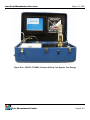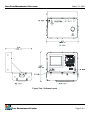
1
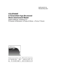
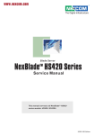
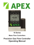
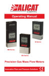
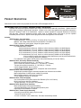
Advanced
Technology
PRODUCT DESCRIPTION
Meyer Tool, Inc.
Flow
Measurement
Center
Lean Flow Measurement Solutions
3055 Colerain Avenue
Cincinnati, Ohio 45225
1-800-786-7362
Definitions for terms used in this proposal can be found in ATD whitepaper 00273-4.
Part Number 5000-33-3702NA5, Suitcase Airflow Test System
Suitcase size airflow test system complete with a bank of sonic nozzles and built in test fixture. System uses five
built-in sonic nozzles for single button operation. Simple to use, three step graphical test procedure operates in
Microsoft® Windows® 2000 or XP Professional. System is network capable for corporate distribution of software
and test data. Real time statistical process control chart is updated during each test to give the operator
immediate process control. System comes programmed with test algorithms for most OEM.
Includes:
5000-33-3702-1, Case Assembly
Outside dimension: 32.25, by 20.25 by 15 inches (82 by 51 by 38 cm)
Material: 6061 deep drawn aluminum heat-treated to a condition of T6
Finish, wash prime, epoxy primer, Meyer blue gloss enamel.
5000-33-3702-2, Primary Element Bank
Five calibrated sonic nozzles:
0.026 inch diameter (0,66 mm), 0.0003 to 0.0013 Lbm/sec (0,00014 to 0,00059 Kg/sec)
0.042 inch diameter (1,07 mm), 0.0005 to 0.0033 Lbm/sec (0,00023 to 0,00150 Kg/sec)
0.067 inch diameter (1,70 mm), 0.0014 to 0.0089 Lbm/sec (0,00064 to 0,00404 Kg/sec)
0.107 inch diameter (2,72 mm), 0.0038 to 0.0234 Lbm/sec (0,00172 to 0,01061 Kg/sec)
0.172 inch diameter (4.37 mm), 0.0101 to 0.0616 Lbm/sec (0,00458 to 0,02794 Kg/sec)
Note: nominal flow range listed above actually dependents upon physical characteristics
of sonic nozzle as defined by calibration.
Five calibrated 3 wire platinum RTD probes, 492 to 580 ºRankine (273 to 322 ºKelvin).
5000-33-3702-3, Secondary Element Assembly
Barometric pressure transducer, 0 – 25 PSIA (0 – 1,7 bars)
Sonic nozzle inlet pressure transducer, 0 – 100 PSIG (0 – 6,9 bars)
Test part inlet pressure transducer, 0 – 50 PSIG (0 – 3,4 bars)
8 step voltage standard, plug-in module.
6 channel RTD temperature transmitter, multiplexer and nozzle switcher
5000-33-3702-4, Flow Control System
Single button operation triggers automatic adjustment of reference test condition.
Manual adjustment of reference test condition is provided.
Manual supply pressure cutoff valve is provided.
¾ inch Swagelok® supply air connection.
5000-33-3702-5, Fixture Assembly
One 3 wire platinum RTD probe, 492 to 580 ºRankine (273 to 322 ºKelvin).
Built-in test plenum with flow conditioner.
Test part envelope, 3.57 inch (9.07 cm) diameter.
5000-33-3702-6, Bottom Panel Assembly
Black anodized panel with engraved labeling.
1/8 inch bulkhead fitting for instrumentation pressure ports.
Input/Output Instrumentation connector.
5000-33-3702-7, Power Supply Assembly
150 watt universal power supply, plug-in module.
T series RFI power line filter.
115 VAC or 230VAC ±10%, 50/60 Hertz, 725 watts automatically sensed.
Page 1 of 5
LEAN FLOW MEASUREMENT SOLUTIONS
March 15, 2004
5000-33-3702-8, Top Panel Assembly
Black anodized panel with engraved labeling.
Parallel printer port.
Serial communication port.
Keyboard and mouse port.
UTP network port.
Input/Output Instrumentation connector.
5000-33-3702-9, Panel Assembly
Intel Pentium III, 700 MHz.
128 Mb SDRAM, PC100.
20 GB Hard drive.
3 ¼” floppy drive.
24X CDROM drive.
14.1” TFT LCD monitor.
10 Mbps Ethernet connectivity.
4MB C&T69030 VGA Engine
Windows 2000 operating system.
Data acquisition board by National Instruments
Computer specifications subject to change due to available technology at time of system build.
5000-33-3702-10, Pneumatic Control Assembly
Air actuated ball valves for nozzle selection.
5000-33-3702-20, User Operation Manual
Two copies.
5000-33-3702-22, Site Preparation Manual
5000-33-3702-23, Spare Parts Kit
5000-33-2700-200, Win32AF Application Software
Win32AF Airflow testing software for product testing.
Built-in test algorithms for most OEM gas turbine components.
Simple to use three step graphical test procedure.
Built-in real time Statistical Process Control chart updated every test to give operates immediate
process control information.
Built-in database for storage and retrieval of test parameters.
Network capable for corporate wide distribution of airflow software and test data.
5000-33-200-2 Airflow test software user manual, two copies.
Win32AF System tasks software for performing administrative and maintenance tasks.
5000-33-200-3 System tasks software user manual, two manuals.
Win32AF Trouble shooting software for maintenance and calibration tasks.
Software backup on CDROM.
5000-33-3702-910, Airflow Test System Calibration
Initial calibration of all primary and secondary flow elements.
Sonic nozzle coefficient of discharge and choke ratio calibration, ±0.25% uncertainty, traceable to NIST.
Pressure transducer calibration, ±0.05% of reading or 0.006 PSI (0,0004 bar), which ever is greater
uncertainty, traceable to NIST.
Temperature transducer calibration, ±0.2% of reading uncertainty, traceable to NIST.
Voltage standard calibration, ±300 PPM uncertainty for voltages greater than 0.1 volt, traceable to NIST.
Performance test using master nozzles, ±0.07% to ±0.12% of mass rate of airflow uncertainty, traceable
to NIST.
Calibration test report.
Note: Recommended calibration schedule is 1 year for pressure and voltage, 2 years for temperature,
and 5 years for discharge coefficient (sonic nozzle).
5000-33-3702-980, Training
One time occurrence of training on-site, 2 days.
Flow Measurement Center
Page 2 of 5
LEAN FLOW MEASUREMENT SOLUTIONS
March 15, 2004
Training material, two copies.
5000-33-3702-990, Installation
On-site assembly, installation, and performance tests, requires 1 day.
5000-33-3702-1000, Warranty
1 year parts and labor on system. See standard terms and condition for details.
Performance Specifications:
Mass rate of airflow uncertainty, flow rates less than 0.0013 Lbm/sec (0,0006 Kg/sec), ±1.00% of reported test
parameter, see ATD whitepaper 00344-1 for detailed discussion.
Mass rate of airflow uncertainty, flow rates equal to or greater than 0.0013 Lbm/sec (0,0006 Kg/sec), ±0.70% of
reported test parameter, see ATD whitepaper 00344-1 for detailed discussion.
Mass rate of airflow repeatability, ±0.000003 Lbm/sec (0,000002 Kg/sec) or ±0.25%, which ever is greater, see
ATD whitepaper 00344-1 for detailed discussion.
Mass rate of airflow reproducibility, ±0.000006 Lbm/sec (0,000003 Kg/sec) or ±0.50%, which ever is greater, see
ATD whitepaper 00344-1 for detailed discussion.
Mass rate of airflow range, 0.0003 to 0.0610 Lbm/sec (0,00014 to 0,0277 Kg/sec) using single nozzle or 0.0003
to 0.1000 Lbm/sec (0,00014 to 0,0454 Kg/sec) using multiple nozzles, nominal values, exact rate may
vary slightly due to manufacturing variations in nozzle throat diameter.
System leak rate, 0.5 PSIG (0,03 bar) maximum for a 10 minute dwell at 80 PSIG (5,5 bars), nozzle valves
closed.
System Particulars:
Case size, 32.25, by 20.25 by 15 inches (82 by 51 by 38 cm)
Case weight, 120 pounds (54.4 Kg)
System warm-up, 15 minutes for rated accuracy, 45 minutes for complete stability.
System operating temperature, +50 to +95 ºFahrenheit (+10 to + 35 ºCelsius)
System operating relative humidity, 20 to 80%, non-condensing
System storage conditions, -22 to +120 ºFahrenheit (-30 to +49 ºCelsius) and relative humidity no more than
80%, non-condensing.
Network connectivity, UTP Ethernet.
Laboratory Equipment Safety, EN61010-1 1993 +A2:1995.
Laboratory Equipment Electromagnetic Compatibility (230VAC 50Hz supply), EN61326-1:1997 +A1:1998.
Requires:
Air supply, 80 SCFM (2,3 CMM) at 110 PSIG (7,6 bars), 0.5 PSI (0,3 bars) maximum supply pressure differential,
air dew point no greater than 0 Fahrenheit (-18 Celsius), particulate size no greater than 1 micron and oil
content less than 10 PPMW.
Test system air supply connection is ¾ inch Swagelok® supply air connection.. Air supply hose not included with
system and must be supplied by Customer.
Electrical supply, 120 ±10% volts AC at 6 amperes, 60 Hz, single phase (US Power). 230 ±10% volts AC at 12
amperes, 50 Hz, single phase (EU Power). Isolated ground less than 5 ohms, noise level less than 10%
of line voltage.
Test system electrical supply connection is 3 wire ground, NEMA 5-15 straight blade plug for U.S. use. A 10 foot
(2.5 m) detachable power cord is included with system.
Ethernet network connection and CAT-5 cable is required for operation with a Customer supplied file server.
Tooling for holding part under test is not included in this proposal.
Excludes:
Tooling necessary to fixture parts under test or run-off testing.
Shipping and taxes.
See ATD standard terms and conditions for addition exclusions.
Flow Measurement Center
Page 3 of 5
LEAN FLOW MEASUREMENT SOLUTIONS
March 15, 2004
Figure One: 5000-33-3702NA5, Suitcase Airflow Test System, Cart Design
Flow Measurement Center
Page 4 of 5
LEAN FLOW MEASUREMENT SOLUTIONS
March 15, 2004
Figure Two: Suitcase Layout
Flow Measurement Center
Page 5 of 5