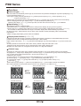
1
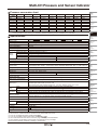
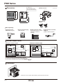
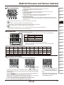
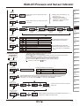
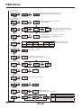
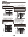
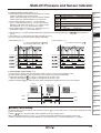
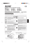
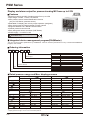
PSM Series
Display and alarm output for pressure/analog MV from up to 8 CH
Features
(available soon)
● Displays pressure and MV of analog sensor from up to 8 CH
● Input range: 0-5VDC, 1-5VDC, DC4-20mA
● Auto pressure sensor model identification function
(only for PSS Series, pressure sensor)
● Selectable PV display part color by output operation (red/green)
● Easy check output by output indicator of each channel
● Supports Modbus RTU / RS485 communication
● Freezer pressure control mode
● Easy wiring with sensor connector (CNE Series)
● Power supply : 12-24VDC ±10%
Please read “Caution for your safety” in operation
manual before using.
(pending)
Integrated device management program(DAQMaster)
You can set and monitor parameters by DAQMaster. Visit our website (www.autonics.com) to download DAQMaster
program, user manual.
Ordering information
PS
M
4
V
D
Option
Control output
Input
Number of channels
Type
Item
D
R
Digital input
RS485 communication
No-mark
P
NPN open collector output
PNP open collector output
V
A
Voltage
Current
4
8
4CH
8CH
M
Multi Channel
PS
Pressure Sensor
Rated pressure range and Max. display pressure
Standard pressure(standard) [
Unit
MPa [
]
kPa [
]
kg/cm2 [
Bar [
psi [
]
]
]
MPa [
]
kPa [
]
kg/cm2 [
]
Bar [
psi [
]
]
mmHg [
inHg [
mmH2O [
]
]
]
※1
Standard pressure(lower) [
Min. display interval Rated pressure
Displayed pressure
Min. display interval
0 to 1.000
-0.050 to 1.100
0.001
-
-
-
0 to 1.000
-50 to 1100
1
0 to 100.0
-5.0 to 110.0
0.1
0 to 10.20
-0.51 to 11.22
0.01
0 to 1.020
-0.051 to 1.122
0.001
0 to 10.00
-0.50 to 11.00
0.01
0 to 1.000
-0.050 to 1.100
0.001
0 to 145.0
-7.2 to 159.6
0.1
0 to 14.50
-0.72 to 15.96
0.01
]
Compound pressure [
]
Rated pressure
Displayed pressure
Min. display interval
Rated pressure
Displayed pressure
Min. display interval
-
-
-
-
-
-
0 to -101.3
5.0 to -101.3
0.1
-101.3 to 100.0
-101.3 to 110.0
0.1
0 to -1.034
0.051 to -1.034
0.001
-1.034 to 1.020
-1.034 to 1.122
0.001
0 to -1.013
0.050 to -1.013
0.001
-1.013 to 1.000
-1.013 to 1.100
0.001
0 to -14.70
0.74 to -14.70
0.01
-14.70 to 14.50
-14.70 to 15.96
0.02
0 to -760
38 to -760
1
-760 to 750
-760 to 824
1
0 to -29.9
1.5 to -29.9
0.1
-29.9 to 29.5
-29.9 to 32.6
0.1
0 to -103.4
5.1 to -103.4
0.1
-103.4 to 102.0
-103.4 to 112.2
0.1
※1: It displays the value by dividing 100. (To read this, multiply the display value by 100.)
※Display pressure range is -5% to 110% of the rated pressure.
E-28
]
Displayed pressure
Negative pressure [
Unit
]
Rated pressure
Multi-CH Pressure and Sensor Indicator
Pressure conversion chart
to Pa
kPa
MPa
kgf/cm
mmHg
mmH2O
psi
bar
from
1Pa
1
0.001
0.000001000 0.000010197 0.007501
0.101972
0.000145038 0.000010000
1kPa
1000.000
1
0.001000
0.010197
7.500616
101.9716
0.145038
0.010000
1MPa
1000000
1000
1
10.197162
7500.61683 101971.553 145.038243 10
1kgf/cm2
98066.54
98.066543
0.09806
1
735.5595
10000.20
14.22334
0.980665
1mmHg
133.322368 0.133322
0.000133
0.001359
1
13.5954
0.019336
0.001333
1mmH2O
9.80665
0.00980
0.000099
0.0735578
1
0.00142
0.000098
1psi
6894.757
6.89757
0.00689
0.070307
51.71630
703.07
1
0.068947
1bar
100000.0
100.0000
0.100000
1.019689
750.062
10196.89
14.50339
1
1inHg
3386.417
3.388418
0.003386
0.034532
25.40022
345.31849
0.491158
0.033863
※Ex) For calculating 760mmHg as kPa:
According to above chart, 1mmHg is 0.133322kPa, therefore 760mmHg is 760×0.133322kPa=101.32472kPa.
2
(A)
Photo
electric
sensor
inHg
0.0002953
0.2953
295.299875
28.95878
0.039370
0.002895
2.036003
29.52998
1
PSM4-V
PSM4-A
PSM8-V
PSM8-A
Depending on pressure type, pressure unit (Refer to ' Rated pressure range')
12-24VDC(ripple P-P : max. 10%)
90 to 110% of rated voltage
Max. 3W
Max. 40mA
4digit
※1
7 Segment LED(red or green )
7 Segment LED(green)
7 Segment LED(red)
8EA
16EA
4EA
8EA
1-5VDC
4-20mA
1-5VDC
4-20mA
12-24VDC 40mA for each channel
Control output
NPN or PNP open collector output
•Load voltage : Max. 30VDC •Load current: 100mA •Residual voltage-NPN : Max. 1V, PNP : Max. 2V
※3
(G)
Connector/
Socket
(H)
Temp.
controller
(I)
SSR/
Power
controller
(J)
Counter
(K)
Timer
± 0.1% ± 2digit (at 23 ± 5℃)
Min. display interval (Refer to '▣Rated pressure range')
±0.1% F.S. ±min. display range
2.5 100, 500, 1000ms
5, 100, 500, 1000ms
1/2000
(N)
Display
unit
(O)
Sensor
controller
Output short overcurrent protection, reverse power polarity protection circuit
Digital input(1-point)
•Contact input: LOW LEVEL input max. 0.2V
•Non-contact input: ON- Residual voltage max. 1.0V, OFF- leakage current max. 0.1mA
Serial communication with SCM-US(USB to Serial converter, sold separately)
RS485 communication (Modbus RTU method)
※5
Sensor connector terminal (CNE-P04-YG, sold separately)
Hirose connector 20-pin(HIF3BA-20D-2.54R, flat cable 20-wire, sold separately) terminal block
Dielectric strength
3000VAC 50/60Hz for 1 min.(between power terminal and case),
※4
1000VAC 50/60Hz for 1 min.(between power terminal and RS485 terminal)
Vibration
Insulation resistance
Ambient temperature
Environment
Ambient humidity
Protection
Accessory
Approval
※6
Weight
0.5mm amplitude at frequency of 10 to 50Hz(for 1 min.) in each of X, Y, Z directions for 2 hours
Max. 100㏁
-10 to 50℃, storage: -20 to 60℃
30 to 85%RH, storage: 30 to 85%RH
IP65(front), the others IP30
Bracket 2EA
(pending)
Approx. 108g (approx. 65g)
(L)
Panel
meter
(M)
Tacho/
Speed/ Pulse
meter
0 to 50℃: ±0.2% F.S. ±2digit, -10 to 0℃: ±0.3% F.S. ±2digit
Serial
※4
RS485
Sensor
Connection
Output
Communication
(D)
Proximity
sensor
(F)
Rotary
encoder
Model
Display range
Power supply
Allowable voltage range
Power consumption
Current consumption
Display digit
Display part 1(PV)
Display part 2
Display
method
CH display part
Output display part
Max. input points
Sensor input
※2
Power supply for sensor
Digital input
(C)
Door/Area
sensor
(E)
Pressure
sensor
Specifications
Display accuracy
Hysteresis
Repeat error
Response time
Resolution
Control output and
display Temp. characteristics
Protection circuits
(B)
Fiber
optic
sensor
(P)
Switching
mode power
supply
(Q)
Stepper
motor&
Driver&Controller
(R)
Graphic/
Logic
panel
(S)
Field
network
device
(T)
Software
(U)
Other
※1: It is able to select at display part 1 color [CLOR] in parameter 2 group.
※2: Do not short +V and 0V of sensor connector. It may cause break inner circuit.
※3: It is only for digital input option model (PSM D).
※4: It is only for RS485 communication option model(PSM R).
※5: For more information about sensor connector plug, refer to '(G) Connector/Socket'.
※6: The weight is with packaging and the weight in parentheses is only unit weight.
※Environment resistance is rated at no freezing or condensation.
E-29
PSM Series
Dimensions
Panel cut-out
(unit: mm)
Min. 65
Min. 65
54.8
48
45 +0.6
0
PC loader port
(SCM-US(USB to Serial
converter, sold separately)
2
48
48
45 +0.6
0
Accessory
58.2
• Bracket
Sold separately
Pressure sensor,
PSS Series (8 type)
Sensor connector plug
(CNE-P04-YG)
4 3 2 1
Output connector cable
(Flat Cable 20-wire, 1.27mm
[AWG28, 2.54mm for
socket])
Communication converter,
SCM-US
(USB to Serial converter)
Ø0.8-Ø1.0
Control output circuit
●NPN open collector output
●PNP open collector output
+V
+V
Main circuit
Overcurrent
protection
OUT2
Overcurrent
protection
※2
Load
Overcurrent
protection
Load
※1
+
※3
-
12-24VDC
Main circuit
※1
OUT1
DI(input) RS485(A+)
DI(0V)
12-24VDC
※1
OUT1
Overcurrent
protection
Load
※1
OUT2
※2
※3
DI(input) RS485(A+)
RS485(B-)
DI(0V)
0V
RS485(B-)
0V
※1: OUT1 and OUT2 consist as the number of channels.
※2: It is only for the digital input option model(PSM D).
※3: It is only for the RS485 communication option model(PSM -
R).
Installation
※Insert this unit into a panel, fasten bracket by pushing with tools as shown.
E-30
Load
+
-
Multi-CH Pressure and Sensor Indicator
Part descriptions
1
3
4
2
5
6
7
8
1. Display part 1(PV)
In RUN mode, it displays the measured value of the current channel.
In setting mode, it displays the set parameter name.
2. Display part 2
In RUN mode, it displays the unit for the measured value of the current channel.
In setting mode, it displays SV of the set parameter.
3. Channel display part
In RUN mode, it displays the channel of the value from the display part 1.
In setting mode, it displays the channel of the set parameter.
4. Control output indicators
PSM4 Series has 4 channels' control output indicators and PSM8 Series has 8 channels'
control output indicators. When the output is ON, the relevant channel's indicator (OUT1 or
OUT2) turns ON.
5. M key: Used to enter setting mode, save SV, move parameters or set preset.
key
In RUN mode, it is used to change the currently displayed channel.
In setting mode, it is used to change the set channel or move the digit for numerical SV.
key: In setting mode, it is used to change SV from each parameter.
7.
key
8.
In RUN mode, press this key for over 2 sec. to enter peak value/auto shift correction value parameters.
In setting mode, it is used to change SV from each parameter.
(H)
Temp.
controller
(I)
SSR/
Power
controller
Type
Voltage input
INPUT
0V
※2
TYPE
+V
1
2
6
8
10
12
14
16
Ch4_
Ch4_
Ch3_
Ch3_
Ch2_
Ch2_
Ch1_
Type
0V
OUT2
OUT1
OUT2
OUT1
OUT2
OUT1
OUT2
PIN NO.
1
3
5
7
8
11
13
15
12-24
Ch8_
Ch8_
Ch7_
Ch7_
Ch6_
Ch6_
Ch5_
Type
VDC
OUT2
OUT1
OUT2
OUT1
OUT2
OUT1
OUT2
No. 19, 20 pins are sub I/O pins and support digital input function (DI) or RS485 communication.
18
Ch1_
OUT1
17
Ch5_
OUT1
(J)
Counter
(K)
Timer
(L)
Panel
meter
(M)
Tacho/
Speed/ Pulse
meter
20
DI(0V)/
RS485(B-)
19
(N)
Display
unit
DI(input)/
RS485(A+)
(O)
Sensor
controller
(P)
Switching
mode power
supply
Zero-point adjustment
※Before using this unit, you must execute zero-point adjustment.
1.
(D)
Proximity
sensor
(G)
Connector/
Socket
Current input
4
3
N·C
※1
2
1
※1: Dot line parts are only for PSM8 Series.
※2: No.2 pin is for auto pressure sensor model identification.
Wire it only for using Autonics pressure sensor, PSS Series (sold separately).
Refer to the E-26 page.
Hirose connector (HIF3FB-20PA-2.54DSA) 20-pin
PIN NO.
(C)
Door/Area
sensor
(F)
Rotary
encoder
Sensor connector input
It is recommended to use Autoncis sensor connector CNE-P04 (sold separately).
PIN NO.
(B)
Fiber
optic
sensor
(E)
Pressure
sensor
6.
Connections
(A)
Photo
electric
sensor
(Q)
Stepper
motor&
Driver&Controller
2.
(R)
Graphic/
Logic
panel
(S)
Field
network
device
Press these
for 4 sec.
1. With opening pressure ports of pressure sensors (supplying atmospheric
pressure), this function is to set zero-point for the current pressure display
value forcibly.
2. Press the + keys for 4 sec. at the same time, the value of display part 1
flashes twice as 000.0 and zero-adjustment is complete.
※You can set the applied channel range for this function at zero-point
adjustment channel range [ZeRS] in parameter 2 group.
●[ RsCH] : Executes zero-point adjustment only for current channel.
●[ RsAL] : Executes zero-point adjustment for all channels.
If there is external pressure and
executing zero-point adjustment,
ERR1 flashes during pressing the
keys.
Remove the external pressure and
re-execute zero-point adjustment
at atmospheric pressure.
E-31
(T)
Software
(U)
Other
PSM Series
Settings
※1
Preset
settings
Parameter 1
group
Parameter 2
group
+
M for less than 2 sec.
M for over 2 sec.
+
RUN
mode
M for over 4 sec.
for over 4 sec.
for
over 2 sec.
Zero-point
adjustment
※2
+
key
Manual return for
freezer control output
Channel
change
※3
High peak value check
M key
※1: When output operation mode[OUtM] is [fOUT], it enters forced
output control mode.
※2: It executes this function when more than one channel's output
operation mode[OUtM]is freezer pressure control[FREZ] and
its control output 2 reset is manual[MAN].
※3: Press the + keys for over 1 sec to initialize high/low peak
value or auto shift correction value.
Low peak value check
M key
Auto shift correction value
check
Parameter setting
●Parameter 1 group
※Parameter 1 group is available to set for each channel.
(Refer to' Channel change and setting'.)
※Press the M key for 3 sec. during setting parameter, it saves SV and returns to RUN mode.
※There is no additional key operation in 30 sec., it returns to RUN mode.
Not saved SV by the M applied and the parameter maintains before SV.
※Dot line parameters may not be displayed by other parameter settings.
※ S : Press any one key among +
keys.
RUN mode
M 2sec.
Parameter 1 group
M
Auto pressure sensor
model identification
When connecting Autonics pressure sensor, PSS Series, it sets pressure
model automatically.
※Auto identification method:
Set as [ON] → Turn PSM power OFF→ Connect PSS
→ Turn PSM power ON
S
M
Input display
S
Standard
M
Pressure type
Set pressure type.
S
E-32
S
Vacuum
Compound
Pressure
Unit
Positive(standard)
kPa[KPA], kgf/cm2[KGF], bar[BAR], psi[PSI], MPa[MPA]
Positive(low)
kPa[KPA], kgf/cm2[KGF], bar[BAR], psi[PSI]
Vacuum
kPa[KPA], kgf/cm2[KGF], bar[BAR], psi[PSI], MPa[MPA], mmHg[MMHG],
inHg[INHG], mmH2O[H2O]
Compound
M
Positive(low)
Positive(standard)
M
Scale decimal
point position
Scale
S
M
Display unit
Select display method for measured input.
※Displays when input
display [DISP] is set
as [STND].
Set decimal point position
for high/low limit scale.
※Displays when
input display [DISP]
is set as [SCAL].
Multi-CH Pressure and Sensor Indicator
Low limit
scale value
(A)
Photo
electric
sensor
S
Set the display value for analog input 1VDC
or DC4mA.
M
High limit
scale value
Output
operation mode
S
Set the display value for analog input 5VDC
or DC20mA.
(D)
Proximity
sensor
(E)
Pressure
sensor
Hysteresis
Hysteresis-Window
comparison output
Window
comparison
output
Freezer
pressure
control
Automatic
sensitivity
setting
Forced output
control
(F)
Rotary
encoder
(G)
Connector/
Socket
S
Parameter
M
Auto shift
applied range
(C)
Door/Area
sensor
S
M
Output type
(B)
Fiber
optic
sensor
※Displays when input display [DISP]
is set as [SCAL].
● Set range: -1999 to 9999
(Decimal point of set range is
depending on scale decimal point
position[DOT] setting.)
S
Parameter
OUT1 output
OUT2 output
Normally Open
Normally Open
Normally Closed
Normally Closed
Normally Open
Normally Closed
Normally Open
Normally Closed
Set range
(I)
SSR/
Power
controller
Set the applied range to auto shift.
※Displays when digital input terminal
[D-IN] is set as [SHFT] in parameter 2
group.
Applies OUT1 of the channel.
M
(H)
Temp.
controller
Set output type as normally open or
normally closed for OUT1/OUT2.
Applies OUT2 of the channel.
Applies OUT1+OUT2 of the channel.
(J)
Counter
(K)
Timer
Applies OUT1+OUT2 of all channels.
※Parameter 2 group is available to set for each channel.
(Refer to' Channel change and setting'.)
※Press the M key for 3 sec. during setting parameter, it saves SV and returns to RUN mode.
※There is no additional key operation in 30 sec., it returns to RUN mode.
Not saved SV by the M applied and the parameter maintains before SV.
※Dot line parameters may not be displayed by other parameter settings.
※ S : Press any one key among +
keys.
●Parameter 2 group
RUN mode
M 4sec.
Parameter 2 group
(L)
Panel
meter
(M)
Tacho/
Speed/ Pulse
meter
(N)
Display
unit
(O)
Sensor
controller
M
Channel copy
S
Copies parameter SV of one channel.
Origianl CH--Subject CH
M
Response time
S
M
Digital input
terminal function
PSM4
PSM8
Original CH
Subject CH
1, 2, 3, 4
1, 2, 3, 4, 5, 6, 7, 8
1, 2, 3, 4, ALL
1, 2, 3, 4, 5, 6, 7, 8, ALL
(P)
Switching
mode power
supply
(Q)
Stepper
motor&
Driver&Controller
Change response time of control output and pressure display value to prevent output chattering.
When response time is longer, the number of digital filters is increased for stable display.
● Set range: 2.5, 100, 500, 1000ms(PSM4) / 5, 100, 500, 1000ms(PSM8)
(R)
Graphic/
Logic
panel
(S)
Field
network
device
S
Set the function to execute by external
digital input.
Auto shift
function
M
Hold
function
(T)
Software
Manual return for
freezer control output
(U)
Other
Digital input applied
channel range
S
M
The channel
All channels
Set the applied channel range for the set digital input function [D-IN].
※Displays for digital input option model.
E-33
PSM Series
Zero-point adjustment
applied channel range
S
M
Set the applied channel range for zero-point
adjustment to change reference pressure.
All channels
The channel
Peak value initialization
applied channel range
S
M
Channel autochange cycle
Set the applied channel range for peak
value initialization.
The channel
All channels
S
Displays the value of one channel and
that of the next channel for the set time
automatically. (unit: sec)
M
Energy save
Saves energy to turn OFF the front except output
indicators when there is no operation for over 1
min. in RUN mode.
S
M
Display part 1
color
S
M
Parameter
Status
Normal
Output
Red
Red
Parameter
Status
Normal
Output
Green
Green
Red
Red
Green
Green
Select color of display part 1
depending on output status.
Communication address
S
● Set range: 01 to 127
M
Communication
speed
S
Set range: 24, 48, 96, 192, 384
Multiply the display value by 100. (unit: bps)
M
Communication parity bit
S
M
Communication stop bit
S
M
Communication response
wait time
S
● Set range: 5 to 99(unit: ms)
M
Communication write
S
M
Parameter
initialization
S
M
Lock
E-34
Initializes parameters
※Be sure that all SVs are initialized.
Parameter Function
S
OFF
LOC1
Unlock
All lock
Locks parameter setting. Preset value change,
zero-point
adjustment and peak values, auto
LOC2
shift correction value initialization are available.
Multi-CH Pressure and Sensor Indicator
High/Low peak value, Auto shift value check
2 sec.
(A)
Photo
electric
sensor
M key
(B)
Fiber
optic
sensor
+
for
over 1 sec.
(C)
Door/Area
sensor
Initializes high
peak value
M key
(D)
Proximity
sensor
+
for
over 1 sec.
Initializes low
peak value
(E)
Pressure
sensor
※1
(F)
Rotary
encoder
M key
+
(G)
Connector/
Socket
for over 1 sec.
Initialize Auto shift value and returns to RUN mode
(H)
Temp.
controller
※1: It displays only when digital input terminal function[D-IN] is [SHFT] in parameter 2 group.
Auto pressure sensor model identification[
(I)
SSR/
Power
controller
]
When connecting Autonics pressure sensor, PSS Series, this unit recognizes pressure model [IN-T] in parameter 1 group
and pressure range automatically.
※Auto identification method: Set auto pressure sensor model identification [AT.SC] as [ON] →Turn PSM power OFF
→ Connect PSS → PSM power ON
※This function is only for Autonics pressure sensor, PSS Series.
※Turn OFF the PSM power and connect PSS. Otherwise, it may cause malfunction.
(K)
Timer
(L)
Panel
meter
Channel change and setting
For manual channel change, set channel auto change cycle [AtCH] as [OFF] in parameter 2 group.
For auto channel change, set channel auto change cycle [AtCH] as [2] or [5] in parameter 2 group.
(M)
Tacho/
Speed/ Pulse
meter
Channel change
● Manual channel change: Press the key in RUN mode. The display part 2 changes channel and the display part 1 displays
the value of this channel.
● Auto channel change: It displays only connected channels. It displays one of the connected channels and the next channel
for the set time (2 or 5 sec.) automatically.
※In auto channel change, when pressing the key to change channel, it displays the value of this channel for 30 sec. and it
displays the next channel automatically.
Channel setting
Parameter 1 group is available to set for each channel. Press the
key key once, channel is changed for the parameter.
Ex)To set auto pressure sensor model identification [AT.SC], and input display [DISP] at CH1, 2, 3 in parameter 1 group.
CH1.auto pressure sensor
model identification
(J)
Counter
CH2.auto pressure sensor
model identification
key
changes
channel
CH3.auto pressure sensor
model identification
(N)
Display
unit
(O)
Sensor
controller
(P)
Switching
mode power
supply
(Q)
Stepper
motor&
Driver&Controller
(R)
Graphic/
Logic
panel
key
changes
channel
(S)
Field
network
device
(T)
Software
M key
M key
CH1. input display
M key
CH2. input display
key
changes
channel
CH3. input display
(U)
Other
key
changes
channel
E-35
PSM Series
Output operation mode
1. Hysteresis mode [HYsM]
2. Window comparison output mode [WIN]
It is able to set certain value for pressure detection level
[ST1, ST2] and hysteresis [HYS1, HYS2].
① It is able to set the range for high[HI-1, HI-2],
low[LO-1, LO-2] limit of pressure detection level when
it is required to detect pressure at a certain range.
② Detection hysteresis is fixed to min. display range.
Parameter Set range
ST1 Min. display pressure < ST1 ≤ Max. display pressure
HYS1 Min. display pressure < HYS1 ≤ST1
ST2 Min. display pressure < ST2 ≤ Max. display pressure
HYS2 Min. display pressure < HYS2 ≤ ST2
Pressure
h
h
Parameter Set range
ㅣㅒLO-1
Min. display pressure ≤ LO-1 ≤ Max. display pressure(3×Min. display interval)
HI-1
Low value +(3 × Min. display interval) ≤ HI-1 ≤ Max.
display pressure
LO-2
Min. display pressure ≤ LO-2 ≤Max. display pressure(3×Min. display interval)
HI-2
Low value +(3 × Min. display interval) ≤ HI-2 ≤ Max.
display pressure
Pressure
Time
OUT1 N.O. ON
OFF
※1
Time
OUT1 N.C. ON
OFF
※1.Min. display range
※1
※1
Time
OUT2 N.O. ON
OFF
OUT2 N.C. ON
OFF
※1
Time
OUT1 N.O. ON
OFF
Time
OUT1 N.C. ON
OFF
3. Hysteresis-Window comparison output mode [HY-W]
① It is available to set hysteresis mode and window
comparison output mode when both hysteresis mode
[ST1, HYS1] and window comparison output mode [LOW,
HIGH]are necessary.
② Detection hysteresis is fixed to min. display range.
Parameter Set range
Min. display pressure < ST1 ≤ Max. display pressure
Min. display pressure < HYS1 ≤ ST1
Min. display pressure ≤ LOW ≤Max. display pressure
-(3×Min. display interval)
Low value +(3 × Min. display interval) ≤ HIGH ≤ Max.
display pressure
Time
Time
Time
OUT2 N.O. ON
OFF
Time
ON
OFF
OUT2 N.C.
Time
4. Automatic sensitivity setting mode [AUTO]
① This mode is to set pressure detection level to the
proper position automatically. It is set by applied
pressure from two positions [ST1,ST2].
② Detection hysteresis is fixed to min. display range.
③ The pressure detection level [SET] is shown in the
following calculation.
)
+
(
=
2
Parameter Set range
Pressure
※1. Min. display range
ST1
Min. display pressure ≤ ST1 ≤ Max. display pressure 1% of rated pressure
ST2
ST1+1% of rated pressure ≤ ST2 ≤ Max. display pressure
SET
Automatic setting: (ST1 + ST2)/2
※1
※1
Pressure
OUT1 N.O. ON
OFF
OUT1 N.C.
ON
OFF
OUT2 N.O.
ON
OFF
OUT2 N.C.
ON
OFF
Time
Time
(
+
)/2 =
※1
※1
Time
Time
OUT1 N.O. ON
OFF
Time
OUT1 N.C. ON
OFF
OUT2 N.O. ON
OFF
OUT2 N.C.
E-36
※1. Min. display range
※1
ON
OFF
Time
Time
Time
Time
Time
Multi-CH Pressure and Sensor Indicator
5. Freezer pressure control mode [FREZ]
① This mode is proper for freezer system's pressure. Control
output 1 is utilized as main output control.
Set the output OFF delay time to prevent frequent ON/OFF.
Control output 2 is utilized as alarm for error pressure.
② Set pressure detection level1 [ST1] and hysteresis 1
[HYS1], output OFF delay time [TIME] for control output 1.
During the output OFF delay time [TIME], it delays output
after hysteresis 1 [HYS1], it turns OFF the output.
③ Set pressure detection level 2 [ST2], hysteresis 2 [HYS2],
manual/auto reset [rA-M] for control output 2.
Parameter Set range
Min. display pressure < ST1 ≤ Max. display pressure
0 < HYS1 < 10% of display range (F.S.)
(unit: digit)
0 ≤ TIME ≤ 3600 (unit: sec.)
Min. display pressure < ST2 ≤ Max. display pressure
0 < HYS2 < 10% of display range (F.S.)
(unit: digit)
< Manual reset [MAN] >
+
) after hysteresis 2
t
t
(F)
Rotary
encoder
OUT1 N.O. ON
OFF
t
Time
OUT1 N.C. ON
OFF
Time
OUT2 N.O. ON
OFF
Time
※1
※1
※t : Output OFF delay time[
t
※1
Time
t
]
(G)
Connector/
Socket
(H)
Temp.
controller
t
(I)
SSR/
Power
controller
OUT1 N.O. ON
OFF
(J)
Counter
Time
OUT1 N.C. ON
OFF
Time
OUT2 N.O. ON
OFF
(K)
Timer
Time
OUT2 N.C. ON
OFF
(L)
Panel
meter
Time
6. Forced output control mode[fOUT]
① This mode is to display pressure with forcibly holding output 1, 2 OFF or ON regardless of SV.
② In RUN mode, press the M key for less than 2 sec. and it is forced output control mode.
③ Whenever pressing the key, output 1 is changed as ON or OFF in turn.
Whenever pressing the key, output 2 is changed as ON or OFF in turn.
④ When pressing the key, output of current channel maintains that status and it moves to next channel.
Displays
current pressure
M
key
Displays current pressure unit
OUT1
ON
OFF
OUT2
ON
OFF
Forced output
operation mode
M
(C)
Door/Area
sensor
(E)
Pressure
sensor
< Auto reset [AUTO] >
※1: Reset signal(digital input or + + )
※t: Output OFF delay time[TIME]
OUT2 N.C. ON
OFF
+
(B)
Fiber
optic
sensor
(D)
Proximity
sensor
AUTO(auto reset) / MAN(manual reset)
● Manual reset [MAN]: Output maintains ON before applying the reset signal (digital input or
[HYS2].
● Auto reset [AUTO]: Output turns OFF after hysteresis 2 [HYS2].
④ Control output1 and control output 2 operate individually.
(A)
Photo
electric
sensor
(M)
Tacho/
Speed/ Pulse
meter
(N)
Display
unit
(O)
Sensor
controller
key
(P)
Switching
mode power
supply
(Q)
Stepper
motor&
Driver&Controller
Displays current pressure unit
(R)
Graphic/
Logic
panel
Time
(S)
Field
network
device
Time
(T)
Software
Preset value setting
Set preset value of output mode for each channel. Press the M key for less than 2 sec., it enters preset parameters varied
by each output mode.
Press the + keys to set preset value within available set range in display part 2.
When control output mode [OUtM] is [F.OUT], it does not set preset and enters forced output control mode.
※Factory defaults of preset values are different by each output mode [OUtM] and input display [DISP] setting.
E-37
(U)
Other
PSM Series
Functions
Pressure type [IN-T]
This unit is able to set measured pressure type by each channel. This parameter is displayed only when input display [DISP]
is set as standard mode [STND].
● Set range: Positive pressure (standard) [POsH], Positive pressure (lower) [POSL], Vacuum pressure [VACU],
Compound pressure [COMP]
● When using auto pressure sensor model identification [AT.SC], pressure type of each channel is set automatically.
● When changing pressure type, display unit [UNIT], scale decimal point position [DOT],
high/low scale value [H-SC/L-SC], preset input value, and auto shift correction value [ShIN] are initialized.
Input display [DISP]
Select display method for measured input.
● Standard mode [STND]: Displays input within the rated pressure display range by pressure type/unit.
● Scale mode [SCAL]: Displays input within the set range (-1999 to 9999) of high/low limit scale value [L-SC/H-SC].
The resolution of PSM is 2000 and if set range is over 2000, display value is automatically proportioned.
Ex) When set range -1999 to 2000 is over two times of the resolution of PSM, the display value is automatically
proportioned.
※When changing input display, preset values are initialized.
Display scale function [H-SC/L-SC]
It displays low limit value (1VDC or DC4mA) / high limit value (5VDC or DC20mA) of transmitted analog input from
pressure sensors as the set high/low limit value (set range: -1999 to 9999).
High/Low limit scale value [L-SC/ H-SC] parameters are displayed only when input display [DISP] is set as scale mode
[SCAL].
● Factory default of low limit scale value: 0000 / Factory default of high limit scale value: 1000
※High limit scale value should be set over low limit scale value ±(3xmin. display unit).
(Ex) When low limit scale is 50, set high limit scale value ≤ 47 or high limit scale≥ 53
Channel copy
Parameter SV and preset values of the particular channel are able to copy to the desired channel or all channels.
Set [original CH--subject CH] in display part 2 at channel copy [COPY] in parameter 2 group. When executing channel
copy, it copies preset values and parameter 1 group's SVs (except [SHOT]).
Copied items are as below.
① Preset values ② Auto pressure sensor model identification [AtSC] ③ Input display [DISP]
④ Pressure type [IN-T] ⑤ Display unit [UNIT] ⑥ Scale decimal point position [DOT]
⑦ Low limit scale value [L-SC] ⑧ High limit scale value [H-SC] ⑨ Output operation mode [OutM]
⑩ Output type [NoNC]
※Auto shift correction value [SHIN] and zero-point adjustment [ZERO] of the subject channel are initialized.
(Ex: Copies parameter SV and preset values of CH2 to CH3. (original CH: 2, subject CH: 3)
CH1. RUN mode
Enters parameter 2 group
M key for
over 4 sec.
Enters channel copy
M key
,
Executes channel copy
Set subject channel
M key
key
※Converts the set
of original CH or
subject CH.
E-38
key input
Set original channel
Multi-CH Pressure and Sensor Indicator
Digital input terminal
(A)
Photo
electric
sensor
This unit executes the set function from digital input terminal [D-IN] in parameter 2 group or communication.
As the below, there are three functions to set digital input.
1. Auto shift [SHFT]:
When initial pressure of the pressure sensor is changed, supply auto shift digital input to correct the current pressure as
reference pressure by the changed level.
● Press the key for over 2 sec. in RUN mode to check/correct auto-shift correction value [SH.IN].
● When not using auto shift, reference pressure is atmospheric pressure(0.0kPa).
※When the channel is forced output control mode or the value is "HHHH" or "LLLL", auto shift does not operate.
※When auto shift digital input is supplied over 5 sec., initial pressures of OUT1, OUT2 for all channels are changed regardless
of the applied channel range.
※When auto shift is set, preset set range is bigger than the rated pressure range as changed initial pressure.
<Preset range after auto-shift correction>
Pressure
Set pressure range(after correction)
Set pressure range(preset set range)
Positive (standard) -5.2kPa to 110.0kPa
-110.0kPa to 110.0kPa
Positive (lower)
-50.0kPa to 1,100kPa
-1,100kPa to 1,100kPa
Vacuum
-101.3kPa to 5.0kPa
-101.3kPa to 101.3kPa
Compound
-101.3kPa to 110.0kPa
-100.0kPa to 110.0kPa
Pressure
Normal primary
pressure
h
Drop of primary
pressure
Pressure
(D)
Proximity
sensor
(E)
Pressure
sensor
(G)
Connector/
Socket
(H)
Temp.
controller
< When Auto Shift is used >
Increase of primary
pressure
(C)
Door/Area
sensor
(F)
Rotary
encoder
▶Example of Auto shift
< When Auto shift is not used >
(B)
Fiber
optic
sensor
Normal primary
pressure
Drop of primary
pressure
(I)
SSR/
Power
controller
Increase of primary
pressure
(J)
Counter
ST1
HYS1
(K)
Timer
Time
Time
OUT ON
OFF
Time
ON
OUT
OFF
Auto shift input
Reference pressure =
Atmospheric pressure
(0.0kPa)
Time
Auto shift input
Reference pressure ≤ Reference pressure ≥
Atmospheric pressure Atmospheric pressure
(0.0kPa)
(0.0kPa)
Correction set value: ST1 = ST1+ ShIN
Correction set value: HYS1 = HYS1 + ShIN
※ ShIN is the reference pressure set by Auto shift input.
(L)
Panel
meter
(M)
Tacho/
Speed/ Pulse
meter
(N)
Display
unit
(O)
Sensor
controller
2. Hold function [HOLD]:
When hold digital input is supplied, it maintains the current display value and control output. When hold digital input is
supplied over 5 sec., this function is applied for all channels.
(P)
Switching
mode power
supply
3. Manual return for freezer control output function [REST]:
For freezer pressure control, when control output 2 is set as manual reset [MAN], it resets maintained control output 2
manually by supplying digital input of manual return for freezer control output.
Press the + + keys in RUN mode, it enters [REST] parameter to set the applied channel for manual return for control
output before executing manual return for freezer control output.
Press the M key and it returns control output 2 manually.
● [HOLD]: Maintains the current output status.
● [ALL]: Returns all output status.
● Each channel: Displays only the CH which output is ON. Returns output of the select CH.
※For digital input option model(PSM D), it is available to set the applied channel range for digital input at digital
input applied channel range [D-CH].
● [DI.CH]: Applies digital input for the channel
● [DI.AL]: Applies digital input for all channels
※By communications, the only one digital input function set at ADDRESS 400053(0034) is available.
E-39
(Q)
Stepper
motor&
Driver&Controller
(R)
Graphic/
Logic
panel
(S)
Field
network
device
(T)
Software
(U)
Other
PSM Series
USB to Serial communication
Connect Autonics communication converter, SCM-US (USB to Serial converter, sold separately) to the PC load port of
PSM to set or monitor parameters from PC by communications.
Communications
From external upper system (PC, PLC etc), it is available to set or monitor parameters and to transmit the data by
communications.
Interface
Application standard
Compliance with EIA RS485
Max. connections
31 units (address: 01 to 127)
Comm. type
2-wire half duplex
Comm. method
Asynchronous
Comm. distance
Within max. 800m
Comm. speed
2400, 4800, 9600, 19200, 38400bps
※It may cause malfunction when changing parameters by
front keys of PSM during connecting communications.
※In same communication line, duplicated communication
address is not allowed. Used twisted pair cable as
communication cable for RS485 communications.
Comm. response time 5 to 99ms
Start bit
1bit(fixed)
Data bit
8bit(fixed)
Parity bit
None, Even, Odd
Stop bit
1, 2bit
Protocol
Modbus RTU(1 Character=fixed as 11Bit)
Error and troubleshooting
Error
Causes
Troubleshooting
ERR1
When external pressure is input while adjusting zero-point.
Remove external pressure and re-try it.
ERR2
When overload is applied to control output.
Remove overload.
LLLL
When applied pressure is lower than display range.
HHHH
When applied pressure is higher than display range.
-HH-LL-HL-
Auto shift correction value error
Apply pressure within the rated display range.
Set the correct SV within the set pressure range
Proper usage
Use separated line from high voltage line or power line in order to avoid inductive noise.
Install power switch or circuit breaker in order to supply or cut off the power.
The switch or circuit breaker should be installed near by users for safety.
Be sure to avoid using the following unit near by machinery making strong high frequency noise. (High frequency welder
& Sewing machine, High capacity SCR unit, etc.)
When input is applied, if "HHHH" or "LLLL" is displayed, there is some problem with measured input, check the line after
power off.
Input line: Shield wire must be used when the measuring input line is getting longer in the place occurring lots of noise.
Installation environment
If shall be used indoor.
Altitude max. 2,000m
Pollution degree 2
Installation category Ⅱ
E-40