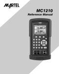
Download User Manual Compact Signal Calibrator CSC201
Transcript
User Manual
Compact Signal Calibrator
CSC201
Ametek JOFRA CSC201 Reference Manual
1. Introduction . . . . . . . . . . . . . . . . . . . . . . . . . . . . . . . . . . . . . . . . . . . . . . . . . . . . . . 1
1.1 Contacting Ametek . . . . . . . . . . . . . . . . . . . . . . . . . . . . . . . . . . . . . . . . . . . . . . . . . . 1
1.2 Standard Equipment . . . . . . . . . . . . . . . . . . . . . . . . . . . . . . . . . . . . . . . . . . . . . . . . . 1
1.3 Safety information . . . . . . . . . . . . . . . . . . . . . . . . . . . . . . . . . . . . . . . . . . . . . . . . . . . 2
2. Calibrator Interface . . . . . . . . . . . . . . . . . . . . . . . . . . . . . . . . . . . . . . . . . . . . . . . . 5
2.1 Main Display . . . . . . . . . . . . . . . . . . . . . . . . . . . . . . . . . . . . . . . . . . . . . . . . . . . . . . . 7
3. Using Measure Modes . . . . . . . . . . . . . . . . . . . . . . . . . . . . . . . . . . . . . . . . . . . . 11
3.1 Measuring Temperature . . . . . . . . . . . . . . . . . . . . . . . . . . . . . . . . . . . . . . . . . . . . . 11
3.2 Measuring Pressure . . . . . . . . . . . . . . . . . . . . . . . . . . . . . . . . . . . . . . . . . . . . . . . . 12
4. Using Source Modes . . . . . . . . . . . . . . . . . . . . . . . . . . . . . . . . . . . . . . . . . . . . . . 14
4.1 Setting 0% and 100% Output Parameters . . . . . . . . . . . . . . . . . . . . . . . . . . . . . . . 14
4.2 Using Auto Output Functions . . . . . . . . . . . . . . . . . . . . . . . . . . . . . . . . . . . . . . . . . 14
4.3 Sourcing Thermocouples . . . . . . . . . . . . . . . . . . . . . . . . . . . . . . . . . . . . . . . . . . . . 15
4.4 Sourcing Ohms/RTDs . . . . . . . . . . . . . . . . . . . . . . . . . . . . . . . . . . . . . . . . . . . . . . . 16
5. Remote Operation . . . . . . . . . . . . . . . . . . . . . . . . . . . . . . . . . . . . . . . . . . . . . . . . 18
6. Specifications . . . . . . . . . . . . . . . . . . . . . . . . . . . . . . . . . . . . . . . . . . . . . . . . . . . 19
7. Maintenance . . . . . . . . . . . . . . . . . . . . . . . . . . . . . . . . . . . . . . . . . . . . . . . . . . . . 22
7.1 Replacing Batteries . . . . . . . . . . . . . . . . . . . . . . . . . . . . . . . . . . . . . . . . . . . . . . . . . 22
7.2 Cleaning the Unit . . . . . . . . . . . . . . . . . . . . . . . . . . . . . . . . . . . . . . . . . . . . . . . . . . . 22
7.3 Service Center Calibration or Repair . . . . . . . . . . . . . . . . . . . . . . . . . . . . . . . . . . . 22
7.4 Replacement Parts & Accessories . . . . . . . . . . . . . . . . . . . . . . . . . . . . . . . . . . . . . 23
1. Introduction
The AMETEK CSC201 Compact Signal Calibrator is a handheld, batteryoperated instrument that measures and simulates physical and electrical
parameters. The calibrator has the following features and functions:
• A large easy to read display used to display all supported physical and
electrical parameters.
• Temperature measurement and simulation using resistance temperature
detectors (RTDs), thermocouples (TCs) and thermistors.
• Signal measurement and sourcing capabilities for resistance and voltage
(millivolts) in the RTD and TC mode.
• Extended and comprehensive pressure measurement capabilities with
JOFRA APM
• A thermocouple (TC) input/output terminal with automatic reference-junction
temperature compensation.
• An interactive menu
• Complete RS232 interface for remote control
1.1 Contacting Ametek
US, Canada, Latin America
Europe, Africa, Middle East
Asia
AMETEK TCI at 1-800-527-9999
AMETEK Denmark A/S at
+ 45 4816 8000
AMETEK Singapore Pte. Ltd. at
+ 65 (64) 842 388
1.2 Standard Equipment
Check to see if your calibrator is complete. It should include:
CSC201 Calibrator
Instruction Manual
Test Leads
1
1.3 Safety information
Symbols Used
The following table lists the International Electrical Symbols. Some or all of
these symbols may be used on the instrument or in this manual.
Symbol
Description
AC (Alternating Current)
AC-DC
Battery
CE Complies with European Union Directives
DC
Double Insulated
Electric Shock
Fuse
PE Ground
Hot Surface (Burn Hazard)
Read the User’s Manual (Important Information)
Off
On
Canadian Standards Association
This calibrator must be recycled or disposed of properly (2002/96/EC).
2
The following definitions apply to the terms “Warning” and “Caution”.
• “Warning” identifies conditions and actions that may pose hazards to the
user.
• “Caution” identifies conditions and actions that may damage the
instrument being used.
Use the calibrator only as specified in this manual, otherwise injury and
damage to the calibrator may occur.
! Warning
The CSC201 is designed to calibrate and measure low voltage process
signals. To ensure the safety of the operator, DO NOT connect the CSC201
to inputs greater than 30 Volts.
! Warning
To avoid possible electric shock or personal injury:
• Do not apply more than the rated voltage. See specifications for
supported ranges.
• Follow all equipment safety procedures.
• Never touch the probe to a voltage source when the test leads are
plugged into the current terminals.
• Do not use the calibrator if it is damaged. Before you use the calibrator,
inspect the case. Look for cracks or missing plastic. Pay particular
attention to the insulation surrounding the connectors.
• Select the proper function and range for your measurement.
• Make sure the battery cover is closed and latched before you operate the
calibrator.
• Remove test leads from the calibrator before you open the battery door.
• Inspect the test leads for damaged insulation or exposed metal. Check
test leads continuity. Replace damaged test leads before you use the
calibrator.
• When using the probes, keep your fingers away from the probe contacts.
Keep your fingers behind the finger guards on the probes.
• Connect the common test lead before you connect the live test lead.
When you disconnect test leads, disconnect the live test lead first.
• Do not use the calibrator if it operates abnormally. Protection may be
impaired. When in doubt, have the calibrator serviced.
• Do not operate the calibrator around explosive gas, vapor, or dust.
3
• When using a pressure module, make sure the process pressure line is
shut off and depressurized before you connect it or disconnect it from the
pressure module.
• Disconnect test leads before changing to another measure or source
function.
• When servicing the calibrator, use only specified replacement parts.
• To avoid false readings, which could lead to possible electric shock or
personal injury, replace the battery as soon as the battery indicator
appears.
• To avoid a violent release of pressure in a pressurized system, shut off the
valve and slowly bleed off the pressure before you attach the pressure
module to the pressure line.
• To avoid personal injury or damage to the calibrator, use only the
specified replacement parts and do not allow water into the case.
! Caution
To avoid possible damage to calibrator or to equipment under test:
• Disconnect the power and discharge all high-voltage capacitors before
testing resistance or continuity.
• Use the proper jacks, function, and range for your measurement or
sourcing application.
• If the message changes to "OL" the range limit is exceeded and the
pressure source must immediately be removed from the APM to prevent
damage to the pressure transducer inside.
• Maximum torque allowed is 13.5 Nm/10 ftlbs. NEVER exceed the torque
allowed.
• To avoid damaging the plastic lens and case, do not use solvents or
abrasive cleansers.
Clean the calibrator with a soft cloth dampened with water or water and mild
soap.
4
2. Calibrator Interface
Figure 1 shows the location of the input and output connections on the
calibrator, while Table 1 describes their use.
TC
F1
F2
F3
3W
RTD
4W
HOME
6
1
5
4
3
2
Figure 1. Input/Output Terminals
Table 1: Input and Output Terminals
No.
Name
Description
1
TC input/output
erminal for measuring, or simulating thermocouples.
T
Accepts miniature polarized thermocouple plugs with flat
in-line blades spaced 7.9 mm (0.312 in) center to center.
2,3
Source/Measure
RTD 2W
Terminals for sourcing and measuring 2W RTDs and
resisitance. Sense terminals for 4W RTD and resisitance
measurement
4,5
Measure RTD
3W 4W
Terminals for performing RTD measurements with 3-wire
or 4-wire setups.
6
Pressure module
onnects calibrator to a pressure module for pressure
C
connector/Serial port measurements or connects calibrator to a PC for remote
control.
5
Figure 2 shows the location of the keys on the calibrator. Table 2 lists the
functions of each key.
1
F1
3
F2
F3
HOME
4
5
2
Figure 2. Keypad
Table 2. Key Functions
No.
Name
Function
1
Function Keys
These keys are used in various ways, primarily to configure the calibrator
2
ON/OFF Key
This key is used to turn the calibrator on and off
3
Home
Returns to home menu on the menu bar.
4
Backlight Key
This key is used to turn the backlight on and off
5
Cursor Keys
These keys are used for setting user inputed values
6
2.1 Main Display
1
2
3
P100(90)385
5
0.0 °C
4
RTD IN 4W
6
CONFIG
MORE
Figure 3. Display
The display of the calibrator, shown in Figure 3, is divided into two sections:
the main display and the menu bar.
The main display is used for both measuring and sourcing.
The menu bar is used to setup the display to perform the desired function.
Table 3 explains the different parts of the display:
Table 3: Display Functions
No.
Name
Description
1
Primary Parameters
Determines what parameter is going to be measured or
sourced.
The available options are TC (thermocouple), RTD, and
PRESSURE.
2
Input/Output control
Switches the display between input mode (read), and
output mode (source).
3
Additional Settings
Available only for TC (thermocouple), and RTD measurements. For TC this setting turns the CJC (Cold
Junction Connection) on and off.
For RTD measure [RTD IN], his setting sets the number
of wires used in the measurement (2-wire, 3-wire, or
4-wire)
4
Units
Shows what unit the measurement or source value is in.
Available options are °C, °F and K for RTD and TC.
5
Sensor Types
Allow for measurements to be made for different types
of RTDs and TCs. All types are shown in the
Specifications.
6
Numeric Displays
Display the numeric values of the signal being measured, or sourced. An “OL” reading indicates an out of
range or overload condition.
7
2.2 Menu Bar
The parameters on the display are controlled by the menu bar, which is
located at the bottom of the LCD. The function keys (F1, F2, and F3) are
used to navigate through all the levels and choices of the menu bar. Refer to
the menu tree for a clarification on the layout of all the levels.
The top level of the menu is the home menu. It can be accessed anytime by
pressing the HOME key. There are two variations of the home menu: the
input home menu and the output home menu.
There are up to three options for the input home menu. They are
[CONFIG], [ZERO] and [MORE]. [CONFIG] is used to enter the parameter
selection menu. [ZERO] is only available when the pressure mode is
selected. [MORE] allows access to further menus.
CONFIG
ZERO
MORE
In the output home menu there are three active options, [CONFIG], [STEP]
or [RAMP] and [MORE]. [CONFIG] and [MORE] serve the same purpose as
CONFIG
RAMP
MORE
in the input home menu. STEP or RAMP either steps or ramps the output.
The contrast menu is usually the next menu level. Its options are
[CONTRAST], [NEXT], and [DONE]. The [CONTRAST] option is used to
adjust contrast. [NEXT] proceeds to the auto off main menu, and [DONE]
returns to home menu. Contrast is adjusted using the cursor keys.
The auto off main menu contains the options [AUTO OFF], [NEXT], and
[DONE].
The [AUTO OFF] option is used to turn the automatic shutoff on and off and
set the amount of time the unit needs to stay dormant to shut off. [NEXT]
and [DONE] return to the home menu.
8
AUTO FUNC NEXT
DONE
When the calibrator is in any source mode, the auto output main menu is
added. The options available on this menu are [AUTO FUNC], [NEXT] and
[DONE]. The [AUTO FUNC] option allows you to turn the RAMP/STEP
functions on or off. [NEXT] is used to access the contrast main menu and
done returns to the home menu.
9
Home Menu
CONFIG
Parameter Selection
SELECT
NEXT
If calibrator is in
Source mode
DONE
Home Menu
CONFIG
MORE
MORE
If calibrator is in
Measure mode
Auto Output Main Menu
AUTO FUNC NEXT DONE
Contrast Menu
CONTRAST NEXT
DONE
Home Menu
CONFIG
Auto Off Menu
AUTO OFF NEXT
DONE
Home Menu
CONFIG
MORE
Figure 4. Simplified Menu Tree
10
MORE
3. Using Measure Modes
3.1 Measuring Temperature
TC IN CJC ON
J
0.0 °C
3.1-1 Using Thermocouples
The calibrator supports the following
thermocouple types: B, C, E, J, K, L, N, R,
S, T, U, BP, and XK. The characteristics of
MORE
CONFIG
all the types are described in the
Specifications section. The calibrator also
has a Cold Junction Compensation (CJC) function. Normally this function
should be ON and the actual temperature of the thermocouple will be
measured. With CJC OFF, the calibrator will measure the difference between
the thermocouple at the junction and at its TC input terminal.
Note: CJC off mode should only be used when calibration is being done
using an external ice bath.
To use the thermocouple to measure temperature, follow these steps:
1.Attach the thermocouple leads to the TC miniplug, and insert the plug
into the input/output of the calibrator, as in Figure 5.
Note: For best accuracy wait 2 to 5 minutes for the temperature between
the miniplug and the calibrator to stabilize before any measurements are
taken.
2. Press [CONFIG] to enter the configuration mode.
3.Select TC from the primary parameters. Choose [IN] in the input/output
control, and then the thermocouple type from the sensor types. The
temperature unit may also be changed from Celsius to Fahrenheit or
Kelvin.
The calibrator can also measure the mV signal from a Thermocouple, which
can be used along with a table in case the corresponding TC type is not
supported by the calibrator. To do so, proceed as above and choose mV as
a sensor type.
TC PLUG
+
–
3W
RTD
Note: The TC wire
used must match the
thermocouple type
being calibrated.
4W
Figure 5. Measuring Temperature Using Thermocouple Terminals
11
3.1-2 Using Resistance-Temperature-Detectors (RTDs)
The supported types of RTDs are shown in the Specifications section.
RTDs are characterized by their 0°C resistance, R0. The calibrator
accepts two, three, and four wire inputs, with four wire input being the
most accurate.
To use the RTD option, apply the following steps:
1.
2.Select RTD from the primary parameters. Select [IN] from input/
output control.
3.Choose 2, 3, or 4-wire connection [2W, 3W, 4W]. (4-wire allows for
the most precise measurement)
4.
Select RTD type from the sensor types.
5.
Attach RTD leads as shown in Figure 6.
Press [CONFIG] to enter the configuration mode..
3W
+
+
–
–
RTD
RTD IN 4W
3W
RTD
4W
RTD
4W
2W
P100(90)385
0.0 °C
RTD
CONFIG
MORE
+
+
–
–
Figure 6. Measuring Temperature with RTD Connection
Resistance can also be measured using this function. To do so, use the
above procedure and choose OHMS from the sensor types. This option
can be used along with a table to measure an RTD which is not
programmed into the calibrator.
3.2 Measuring Pressure
! Warning!
To avoid a violent release of pressure in a pressurized system, shut off the
valve and slowly bleed off the pressure before you attach the pressure
module to the pressure line.
12
! Caution
To avoid mechanically damaging the pressure module, never apply more
than 13.5 Nm/10 ftlbs. of torque between the pressure module fittings, or
between the fittings an the body of the module.
To avoid damaging the pressure module from overpressure, never apply
pressure above the rated maximum printed on the module.
To avoid damaging the pressure module from corrosion, use it only with
specified materials. Refer to the pressure module documentation for
material compatibility.
To measure pressure, follow these steps:
1. Connect the pressure module to the calibrator as shown in Figure 7.
2. Press [CONFIG] to enter the configuration mode.
3. Select [PRESSURE] from the primary parameters.
4. Select the desired measuring unit.
5.Zero the pressure module. The zero function on the calibrator can be
found in the pressure zeroing menu.
VALVE
PRESSURE
MODULE
F1
F2
F3
HOME
Figure 7. Connections for Measuring Pressure
3.2-1 Zeroing with Absolute Pressure Modules.
To zero, adjust the calibrator to read a known pressure, such as barometric
pressure.
To adjust the calibrator, follow these steps:
13
1. S
elect [ZERO
]. [SET REFERENCE ABOVE] will appear.
Enter the pressure using the cursor keys.
2. The calibrator stores the Barometric zero offset in non-volatile memory.
The zero offset is stored for one absolute pressure module at a time. If a
new absolute module is connected this process must be repeated.
4. Using Source Modes
The calibrator can generate calibrated signals for testing and calibrating. It
can simulate the electrical output of RTD and thermocouple temperature
sensors.
4.1 Setting 0% and 100% Output Parameters
To set the 0% and 100% points, use the following steps:
1.Use [CONFIG] to enter the configuration mode and choose the desired
primary parameter.
2.Select output [OUT] from the input/output control, and enter the desired
value. For example select [RTD OUT].
3.Press the right arrow key to bring up alternate functions for the function
keys. Use the arrow keys to adjust the value to the desired 0% value.
Press and hold the 0% key until “Set 0%” flashes on the screen.
4.Press the right arrow key to bring up alternate functions for the function
keys. Use the arrow keys to adjust the value to the desired 100% value.
Press and hold the 100% key until “Set 100%” flashes on the screen.
5.Use the F2 key to cycle from 0% to 100% in either 10% or 25%
increments, depending on which is selected.
4.2 Using Auto Output Functions
There are two Auto Output functions; [STEP] and [RAMP]. When the [STEP]
function is selected the calibrator steps from the 0% set source value to the
100% set source value in 10% or 25% increments. The word [STEP] turns to
[STEPPING] when the [STEP] function is active. The [RAMP] function ramps
the calibrator output from the 0% to 100% set source values. When the
[RAMP] function is active the word [RAMP] turns to [RAMPING]. Both the
[STEP] and [RAMP] functions will continue from 0% to 100% and back
again until a key is pressed.
14
+–
3W
RTD
4W
TC PLUG
Note: TC wire used must match
the thermocouple type being calibrated.
+
–
Figure 8. Connections for Outputting Thermocouples
4.3 Sourcing Thermocouples
To source a thermocouple use the following steps:
1.Connect the thermocouple leads to the appropriate polarized TC
miniplug, and insert the plug into the TC terminals on the calibrator, as
shown in Figure 8.
2.Press [CONFIG] and choose thermocouple [TC] from the primary
parameters.
3. Choose output [OUT] from the input/output control.
4. Select the desired thermocouple type from the sensor types.
5. Enter the temperature using the cursor keys.
TC OUT CJC ON
J
100.0 °C
CONFIG
MORE
3W
RTD
4W
Figure 9. Connections for Outputting RTDs
15
4.4 Sourcing Ohms/RTDs
To source an RTD, follow these steps:
1.Press [CONFIG] and choose [RTD] from the primary parameters.
2.Choose output [OUT] from the input/output control, and select RTD type
from the sensor types.
3. Connect the calibrator to the instrument being tested, as in Figure 19.
4. Enter the temperature or resistance using the cursor keys.
+
–
–
+
+
–
–
3W
4
+
Use stackable
test leads for
shared connections
4W
1
4
1
3
3
2
2
Figure 10. Using a 3- or 4-wire Connection for RTDs
RTD OUT
P100(90)385
100.0 °C
CONFIG
MORE
Note: The calibrator simulates a 2-wire RTD. To connect 3- or 4-wire
transmitter, use stacking cables, as shown in Figure 10.
16
4.4-1 Custom RTD
A custom curve-fit PRT may be entered into the calibrator for sourcing
and measuring. To do so follow these steps:
1.Switch to lower display. Select RTD and set sensor type to
CUSTOM.
2.Custom Coefficients can only be entered through the serial port.
The custom function uses the Calendar-Van Dusen equation for
outputting and measuring custom RTDs. The coefficient C is only used
for temperatures below 0°C. Only A and B coefficients are needed for
the range above 0°C, so coefficient C should be set to 0. The R0 is the
resistance of the probe at 0°C. The ITS 90 coefficients for PT385,
PT3926, and PT3616 are shown in Table 4.
Table 4. RTD Coefficients
RTD
Range(°C)
R0
Coefficient A
Coefficient B
Coefficient C
PT385
-260 - 0
100
3.9083x10⁻³
-5.775x10⁻⁷
-4.183x10⁻¹²
PT385
0 - 630
100
3.9083x10⁻³
-5.775x10⁻⁷
---
PT3926
Below 0
100
3.9848x10⁻³
-5.87x10⁻⁷
-4x10-12
PT3926
Above 0
100
3.9848x10⁻³
-5.87x10⁻⁷
---
PT3916
Below 0
100
3.9692x10⁻³
-5.8495x10⁻⁷
-4.2325x10⁻¹²
PT3916
Above 0
100
3.9692x10⁻³
-5.8495x10⁻⁷
---
17
5. Remote Operation
The calibrator can be remotely controlled using a PC terminal, or by a
computer program running the calibrator in an automated system. It uses an
RS232 serial port connection for remote operation. With this connection the
user can write programs on the PC, with Windows languages like Visual
Basic to operate the calibrator, or use a Windows terminal, such as Hyper
Terminal, to enter single commands. Typical RS232 remote configurations
are shown in Figure 11.
COM PORT
F1
HOME
F2
F3
Optional RS-232 Cable
Figure 11. Calibrator-to-Computer Connection
18
6. Specifications
One year at 23°C ± 5°C, unless specified otherwise. Outside of this range the
stability of the measurements is ± 0.003% of FS/°C.
Table 5: General Specifications
Operating Temperature
-10°C to 50°C
Storage Temperature
-20°C to 60°C
Power
4 X AA batteries; Alkaline or optional rechargeable
Battery Life
Approximately 20 hours
Serial Communications
ASCII; RS232
CE - EMC
EN61326: 2006, ANNEX A
Safety
EN/IEC 61010-1:2010 3rd Edition (Low Voltage Directive)
Size
9.3" x 3.8" x 2.3" (23.5cm x 9.7cm x 5.7cm)
Weight
Approximately 21oz. (0.6kg)
Table 6: Resistance Measurement
Range
Accuracy
(% of reading ± floor)
Ohms low
0.00Ω - 400.0Ω
0.015% ± 0.03Ω
Ohms high
401.0Ω - 4000.0Ω
0.015% ± 0.3Ω
Table 7: Resistance Source
Range
Excitation Current
Accuracy
(% of reading ± floor)
Ohms low 5.0Ω - 400.0Ω
0.1mA - 0.5mA
0.015% ± 0.1Ω
0.5mA - 3mA
0.015% ± 0.03Ω
0.05mA - 0.8mA
0.015% ± 0.3Ω
5.0Ω - 400.0Ω
Ohms high 400Ω - 1500Ω
1500Ω - 4000Ω
0.05mA - 0.4mA
0.015% ± 0.3Ω
Note: Unit is compatible with smart transmitters and PLCs. Frequency response is <= 5ms.
Table 8: Thermocouple Measurement/Source
Range
Accuracy
(% of reading ± floor)
Read (mV)
-10.000mV - 75.000mV
0.015% ± 10µV
Source (mV)
-10.000mV - 75.000mV
0.015% ± 10µV
Maximum current output in voltage ranges is 1mA with an output impedance of <= 1Ω
19
Table 9: Thermocouple Read and Source (errors in °C)
Range (°C)
Accuracy (°C)
TC Type
Minimum
Maximum
CJC OFF
CJC ON
J
-210.0
-150.0
0.4
0.6
-150.0
1200.0
0.2
0.4
-200.0
-100.0
0.5
0.7
-100.0
600.0
0.2
0.4
600.0
1000.0
0.3
0.5
1000.0
1372.0
0.4
0.6
-250.0
-200.0
1.5
1.7
-200.0
0.0
0.5
0.7
0.0
400.0
0.2
0.4
-250.0
-200.0
1.0
1.2
-200.0
-100.0
0.3
0.5
-100.0
1000.0
0.2
0.4
0.0
200.0
1.7
1.9
200.0
1767.0
1.0
1.2
0.0
200.0
1.7
1.9
200.0
1767.0
1.1
1.3
600.0
800.0
1.5
1.7
K
T
E
R
S
B
C
800.0
1000.0
1.2
1.4
1000.0
1820.0
1.0
1.2
0.0
1000.0
0.5
0.7
1000.0
2316.0
1.5
1.7
XK
-200.0
800.0
0.2
0.4
BP
0.0
800.0
1.9
2.1
800.0
2500.0
0.6
0.8
L
-200.0
900.0
0.2
0.4
U
-200.0
0.0
0.4
0.6
0.0
600.0
0.2
0.4
-200.0
-100.0
0.8
1.0
-100.0
1300.0
0.3
0.5
N
CJC error outside of 23 ± 5°C is 0.05°C/°C
20
Table 10: RTD Read and Source
RTD Type
Range (°C)
Accuracy (°C) 1 year
Minimum
Maximum
Measure
4W/Source
Measure
3W
-200
100
0.85
2.20
100
400
1.00
2.50
400
800
1.20
2.80
-200
100
0.20
0.50
100
400
0.30
0.60
400
800
0.40
0.70
-200
100
0.15
0.25
100
400
0.20
0.35
400
800
0.30
0.45
-200
100
0.40
0.50
100
630
0.50
0.60
-200
100
0.20
0.25
100
630
0.25
0.30
P500(90)385
-200
100
0.20
0.25
100
630
0.30
0.35
P1K(90)385
-200
100
0.15
0.20
100
630
0.20
0.25
-200
100
0.20
0.50
100
400
0.30
0.60
400
800
0.40
0.70
-200
100
0.15
0.25
100
400
0.20
0.35
400
800
0.30
0.45
-200
100
0.10
0.25
100
630
0.20
0.35
M10(90)427
-100
260
0.75
2.00
M50(90)428
-180
200
0.15
0.40
M100(90)428
-180
200
0.10
0.20
H120(90)672
-80
260
0.10
0.15
P100(90)JIS
-200
100
0.10
0.25
100
630
0.20
0.35
15
50
0.10
0.15
P10(90)385
P50(90)385
P100(90)385
P200(90)385
P400(90)385
P50(90)391
P100(90)391
P100(90)392
YSI(90)400
21
Table 11: Pressure Measurement
Units
Engineering Unit Factor
Psi
1
bar
0.06894757
mbar
68.94757
kPa
6.894757
MPa
0.00689476
kg/cm2
0.07030697
cmH2O @ 4°C
70.3089
cmH2O @ 20°C
70.4336
mmH2O @ 4 °C
703.089
mmH2O @ 20°C
704.336
inH2O @ 4°C
27.68067
inH2O @ 20°C
27.72977
inH2O @ 60°F
27.70759
mmHg @ 0°C
51.71508
inHg @ 0°C
2.03602
Ranges, Resolution and Accuracy are determined by the module
7. Maintenance
7.1 Replacing Batteries
Replace batteries as soon as the battery indicator turns on to avoid false
measurements. If the batteries discharge too deeply the calibrator will
automatically shut down to avoid battery leakage.
Note: Use only AA size alkaline batteries.
7.2 Cleaning the Unit
! Warning
To avoid personal injury or damage to the calibrator, use only the specified
replacement parts and do not allow water into the case.
22
! Caution
To avoid damaging the plastic lens and case, do not use solvents or
abrasive cleansers.
Clean the calibrator with a soft cloth dampened with water or water and mild
soap.
7.3 Service Center Calibration or Repair
Only qualified service personnel should perform calibration, repairs, or
servicing not covered in this manual. If the calibrator fails, check the
batteries first, and replace them if needed.
Verify that the calibrator is being operated as explained in this manual. If the
calibrator is faulty, send a description of the failure with the calibrator. Be
sure to pack the calibrator securely, using the original shipping container if it
is available.
7.4 Replacement Parts & Accessories
SPK-CSC-003
Operating Manual
2206011
Wire adapter kit - Type K thermocouple
2206012
Wire adapter kit - Type T thermocouple
104203
Test lead set
127403
RS232 to 6-pol LEMO
121985
Extension Cable for Pt 100 Sensor - 5 m
121983
Extension Cable for Type K - 5 m
122523
Extension Cable for Type N - 5 m
120519
Thermocouple Male Plug - Type Cu-Cu - White
120518
Thermocouple Male Plug - Type R / S - Green
120517
Thermocouple Male Plug - Type K - Yellow
120516
Thermocouple Male Plug - Type J - Black
120515
Thermocouple Male Plug - Type T - Blue
120514
Thermocouple Male Plug - Type N - Orange
0220016 Rev. C 12/13
23
AMETEK Calibration Instruments
is one of the world’s leading manufacturers
and developers of calibration instruments for
temperature, pressure and process signals as well
as for temperature sensors both from a commercial
and a technological point of view.
JOFRA Temperature Instruments
Portable precision thermometers. Dry-block and
liquid bath calibrators: 5 series, with more than 25
models and temperature ranges from -90° to 1205°C
/ -130° to 2200°F. All featuring speed, portability,
accuracy and advanced documenting functions with
JOFRACAL calibration software.
JOFRA Pressure Instruments
Convenient electronic systems ranging from -25
mbar to 1000 bar (0.4 to 15,000 psi) - multiple
choices of pressure ranges, pumps and accuracies,
fully temperature-compensated for problem-free and
accurate field use.
JOFRA Signal Instruments
Process signal measurement and simulation for
easy control loop calibration and measurement
tasks - from handheld field instruments to laboratory
reference level bench top instruments.
JOFRA / JF Marine Instruments
A complete range of calibration equipment for
temperature, pressure and signal, approved for
marine use.
FP Temperature Sensors
A complete range of temperature sensors for
industrial and marine use.
M&G Pressure Testers
Pneumatic floating-ball or hydraulic piston dead
weight testers with accuracies to 0.015% of reading.
M&G Pumps
Pressure generators from small pneumatic “bicycle”
style pumps to hydraulic pumps generating up to
1,000 bar (15,000 psi).
www.jofra.com
UK
Denmark
Singapore
France
USA
China
Germany
India
Lloyd Instruments Ltd
Tel +44 (0)1243 833 370
[email protected]
AMETEK S.A.S.
Tel +33 (0)1 30 68 89 40
[email protected]
AMETEK GmbH
Tel +49 (0)2159 9136 510
[email protected]
AMETEK Denmark
Tel +45 4816 8000
[email protected]
AMETEK MCT
Tel +1 (727) 536 7831
[email protected]
AMETEK Instruments India Pvt Ltd.
Tel +91 22 2836 4750
[email protected]
Information in this document is subject to change without notice. ©2012, by AMETEK, Inc., www.ametek.com. All rights reserved.
AMETEK Singapore Pte Ltd
Tel +65 6484 2388
[email protected]
AMETEK Inc. - Shanghai
Tel +86 21 5868 5111
AMETEK Inc. - Beijing
Tel +86 10 8526 2111
AMETEK Inc. - Guangzhou
Tel +86 20 8363 4768
[email protected]


