1
MSCANS08 Driver
User Manual
HCS08
Microcontrollers
MSCANS08DUM
Rev. 0.1
03/2007
freescale.com
MSCANS08 Driver User Manual
To provide the most up-to-date information, the revision of our documents on the World Wide Web will be the most
current. Your printed copy may be an earlier revision. To verify that you have the latest information available, refer
to http://www.freescale.com.
The following revision history table summarizes changes contained in this document. For your convenience, the
page number designators have been linked to the appropriate location, and change bars indicate where changes have
been made.
MSCANS08 Driver User Manual, Rev. 0.1
Freescale Semiconductor
3
Revision History
Revision History
Date
Revision
Level
3/2007
0.1
Description
Initial release.
Page
Number(s)
N/A
MSCANS08 Driver User Manual, Rev. 0.1
4
Freescale Semiconductor
Contents
Chapter 1
Overview
Chapter 2
Notations
2.1
2.2
2.3
2.4
Manual Structure . . . . . . . . . . . . . . . . . . . . . . . . . . . . . . . . . . . . . . . . . . . . . . . . . . . . . . . . . . . . . . . . . . . . . .9
Typographical Conventions . . . . . . . . . . . . . . . . . . . . . . . . . . . . . . . . . . . . . . . . . . . . . . . . . . . . . . . . . . . . . .9
Definitions, Acronyms and Abbreviations. . . . . . . . . . . . . . . . . . . . . . . . . . . . . . . . . . . . . . . . . . . . . . . . . .10
References . . . . . . . . . . . . . . . . . . . . . . . . . . . . . . . . . . . . . . . . . . . . . . . . . . . . . . . . . . . . . . . . . . . . . . . . . .10
Chapter 3
CAN Overview
Chapter 4
msCANS08 Overview
Chapter 5
msCANS08 Driver
5.1
5.2
5.2.1
5.2.2
Driver Functionality Overview . . . . . . . . . . . . . . . . . . . . . . . . . . . . . . . . . . . . . . . . . . . . . . . . . . . . . . . . . .15
Configuration . . . . . . . . . . . . . . . . . . . . . . . . . . . . . . . . . . . . . . . . . . . . . . . . . . . . . . . . . . . . . . . . . . . . . . . .16
Driver Configuration . . . . . . . . . . . . . . . . . . . . . . . . . . . . . . . . . . . . . . . . . . . . . . . . . . . . . . . . . . . . . . .16
Message Object Configuration . . . . . . . . . . . . . . . . . . . . . . . . . . . . . . . . . . . . . . . . . . . . . . . . . . . . . . .22
Chapter 6
msCANS08 Driver API
6.1
6.2
6.3
6.4
6.4.1
6.4.2
6.4.3
6.4.4
6.4.5
6.4.6
6.4.7
6.4.8
6.4.9
6.4.10
6.4.11
General . . . . . . . . . . . . . . . . . . . . . . . . . . . . . . . . . . . . . . . . . . . . . . . . . . . . . . . . . . . . . . . . . . . . . . . . . . . . .23
Data Types . . . . . . . . . . . . . . . . . . . . . . . . . . . . . . . . . . . . . . . . . . . . . . . . . . . . . . . . . . . . . . . . . . . . . . . . . .23
Constant Definition . . . . . . . . . . . . . . . . . . . . . . . . . . . . . . . . . . . . . . . . . . . . . . . . . . . . . . . . . . . . . . . . . . .23
Driver Services. . . . . . . . . . . . . . . . . . . . . . . . . . . . . . . . . . . . . . . . . . . . . . . . . . . . . . . . . . . . . . . . . . . . . . .26
CAN_Init . . . . . . . . . . . . . . . . . . . . . . . . . . . . . . . . . . . . . . . . . . . . . . . . . . . . . . . . . . . . . . . . . . . . . . . .26
CAN_Reset . . . . . . . . . . . . . . . . . . . . . . . . . . . . . . . . . . . . . . . . . . . . . . . . . . . . . . . . . . . . . . . . . . . . . .27
CAN_Sleep . . . . . . . . . . . . . . . . . . . . . . . . . . . . . . . . . . . . . . . . . . . . . . . . . . . . . . . . . . . . . . . . . . . . . .27
CAN_Wakeup . . . . . . . . . . . . . . . . . . . . . . . . . . . . . . . . . . . . . . . . . . . . . . . . . . . . . . . . . . . . . . . . . . . .28
CAN_CheckStatus. . . . . . . . . . . . . . . . . . . . . . . . . . . . . . . . . . . . . . . . . . . . . . . . . . . . . . . . . . . . . . . . .29
CAN_ConfigMB . . . . . . . . . . . . . . . . . . . . . . . . . . . . . . . . . . . . . . . . . . . . . . . . . . . . . . . . . . . . . . . . . .30
CAN_CheckStatusMB. . . . . . . . . . . . . . . . . . . . . . . . . . . . . . . . . . . . . . . . . . . . . . . . . . . . . . . . . . . . . .31
CAN_LoadMB . . . . . . . . . . . . . . . . . . . . . . . . . . . . . . . . . . . . . . . . . . . . . . . . . . . . . . . . . . . . . . . . . . .31
CAN_TransmitMB . . . . . . . . . . . . . . . . . . . . . . . . . . . . . . . . . . . . . . . . . . . . . . . . . . . . . . . . . . . . . . . .32
CAN_AbortMB . . . . . . . . . . . . . . . . . . . . . . . . . . . . . . . . . . . . . . . . . . . . . . . . . . . . . . . . . . . . . . . . . . .33
CAN_ReadDataMB. . . . . . . . . . . . . . . . . . . . . . . . . . . . . . . . . . . . . . . . . . . . . . . . . . . . . . . . . . . . . . . .33
MSCANS08 Driver User Manual, Rev. 0.1
Freescale Semiconductor
5
6.4.12
CAN_ReadTimeMB . . . . . . . . . . . . . . . . . . . . . . . . . . . . . . . . . . . . . . . . . . . . . . . . . . . . . . . . . . . . . . .34
Chapter 7
Building Application
7.1
7.2
7.3
7.4
7.5
7.5.1
MCU Resources Usage . . . . . . . . . . . . . . . . . . . . . . . . . . . . . . . . . . . . . . . . . . . . . . . . . . . . . . . . . . . . . . . .35
Physical Interface Connection . . . . . . . . . . . . . . . . . . . . . . . . . . . . . . . . . . . . . . . . . . . . . . . . . . . . . . . . . . .35
CAN Network Setup . . . . . . . . . . . . . . . . . . . . . . . . . . . . . . . . . . . . . . . . . . . . . . . . . . . . . . . . . . . . . . . . . .35
Compilation . . . . . . . . . . . . . . . . . . . . . . . . . . . . . . . . . . . . . . . . . . . . . . . . . . . . . . . . . . . . . . . . . . . . . . . . .36
Linking . . . . . . . . . . . . . . . . . . . . . . . . . . . . . . . . . . . . . . . . . . . . . . . . . . . . . . . . . . . . . . . . . . . . . . . . . . . . .36
CodeWarrior . . . . . . . . . . . . . . . . . . . . . . . . . . . . . . . . . . . . . . . . . . . . . . . . . . . . . . . . . . . . . . . . . . . . .36
Appendix A
msCAN Driver Usage
A.1
A.2
A.3
A.4
A.5
A.6
A.7
A.8
A.9
Driver Initialization . . . . . . . . . . . . . . . . . . . . . . . . . . . . . . . . . . . . . . . . . . . . . . . . . . . . . . . . . . . . . . . . . . .39
Message Buffer Initialization and Configuration. . . . . . . . . . . . . . . . . . . . . . . . . . . . . . . . . . . . . . . . . . . . .39
Transmitting a Data Frame. . . . . . . . . . . . . . . . . . . . . . . . . . . . . . . . . . . . . . . . . . . . . . . . . . . . . . . . . . . . . .40
Receiving a Data Frame . . . . . . . . . . . . . . . . . . . . . . . . . . . . . . . . . . . . . . . . . . . . . . . . . . . . . . . . . . . . . . . .41
Transmitting a Remote Frame . . . . . . . . . . . . . . . . . . . . . . . . . . . . . . . . . . . . . . . . . . . . . . . . . . . . . . . . . . .42
Automatic Reply to a Remote Frame. . . . . . . . . . . . . . . . . . . . . . . . . . . . . . . . . . . . . . . . . . . . . . . . . . . . . .42
Time Stamp . . . . . . . . . . . . . . . . . . . . . . . . . . . . . . . . . . . . . . . . . . . . . . . . . . . . . . . . . . . . . . . . . . . . . . . . .43
Low Power Modes . . . . . . . . . . . . . . . . . . . . . . . . . . . . . . . . . . . . . . . . . . . . . . . . . . . . . . . . . . . . . . . . . . . .43
Reserved Keywords . . . . . . . . . . . . . . . . . . . . . . . . . . . . . . . . . . . . . . . . . . . . . . . . . . . . . . . . . . . . . . . . . . .44
Appendix B
Sample Application
B.1
B.2
B.3
Sample Description . . . . . . . . . . . . . . . . . . . . . . . . . . . . . . . . . . . . . . . . . . . . . . . . . . . . . . . . . . . . . . . . . . .45
Sample Building and Running . . . . . . . . . . . . . . . . . . . . . . . . . . . . . . . . . . . . . . . . . . . . . . . . . . . . . . . . . . .45
CodeWarrior Project . . . . . . . . . . . . . . . . . . . . . . . . . . . . . . . . . . . . . . . . . . . . . . . . . . . . . . . . . . . . . . . . . .45
Appendix C Further Information
C.1
C.2
Application Notes. . . . . . . . . . . . . . . . . . . . . . . . . . . . . . . . . . . . . . . . . . . . . . . . . . . . . . . . . . . . . . . . . . . . .47
Online Training . . . . . . . . . . . . . . . . . . . . . . . . . . . . . . . . . . . . . . . . . . . . . . . . . . . . . . . . . . . . . . . . . . . . . .47
Appendix D
Performance Characteristics
D.1
D.2
Performance Characteristics. . . . . . . . . . . . . . . . . . . . . . . . . . . . . . . . . . . . . . . . . . . . . . . . . . . . . . . . . . . . .49
Memory Consumption . . . . . . . . . . . . . . . . . . . . . . . . . . . . . . . . . . . . . . . . . . . . . . . . . . . . . . . . . . . . . . . . .49
MSCANS08 Driver User Manual, Rev. 0.1
6
Freescale Semiconductor
Chapter 1
Overview
This User Manual describes CAN protocol driver routines for the Freescale msCANS08 CAN 2.0B
peripheral modules which are integrated onto a number of devices from the Freescale S08 product family.
The driver is optimized for a single on-chip msCANS08. The driver emulates the 'full-CAN' model, with
a message buffer per CAN identifier. The number of message buffers is configurable, allowing full control
over RAM requirements.
The main driver features are:
• Optimized for a single msCANS08
• Up to 255 message objects (Standard and Extended Identifiers)
• Up to 32 message buffers
• Advanced priority-based management of queued message objects
• Auto-reply to received Remote Transmission Request Frames
• Auto-receive Data Frames received in response to Remote Transmission Request Frames
• Sleep and Wake-up functions
• Abort transmission function
The driver is supplied as source code and header files.
The supported toolchain is the CodeWarrior compiler V5.1 or later, with ‘C’ header files for user defined
parameters.
MSCANS08 Driver User Manual, Rev. 0.1
Freescale Semiconductor
7
Overview
MSCANS08 Driver User Manual, Rev. 0.1
8
Freescale Semiconductor
Manual Structure
Chapter 2
Notations
2.1 Manual Structure
This user’s manual comprises the following sections.
Chapter 1 Overview provides the msCANS08 driver overview and describes its main features.
Chapter 2 Notations includes a description of the structure of the document, typographical conventions
used, references to other documents, technical support information, and a list of acronyms.
Chapter 3 CAN Overview provides a general description of the CAN specification.
Chapter 4 msCANS08 Overview provides a general description of the msCANS08 module.
Chapter 5 msCANS08 Driver describes the msCANS08 driver configuration and functionality.
Chapter 6 msCANS08 Driver API provides a detailed description of msCANS08 driver run-time services.
Chapter 7 Building Application provides Information regarding setting up a CAN network and describes
the steps for compiling and linking the application.
Appendix A msCAN Driver Usage provides information how to use the msCANS08 driver.
Appendix B Sample Application contains the sequence of actions needed for creation, building and
execution of sample application included into the msCANS08 driver package.
Appendix C Further Information refers to further msCAN information (Application Notes and Online
Training).
Appendix D Performance Characteristics contains msCANS08 driver performance characteristics, such as
ROM and RAM usage, timing and CPU load.
2.2 Typographical Conventions
This manual employs the following typographical conventions:
• italic type is used for all names of directives, macros, constants, routines and variables. Also, this
type is used for special terms.
• courier type is used for code examples in the text.
MSCANS08 Driver User Manual, Rev. 0.1
Freescale Semiconductor
9
Notations
2.3 Definitions, Acronyms and Abbreviations
API
application program interface (a set of data types and functions)
CAN
controller area network
DLC
data length code
IDE
identifier extension
ISR
interrupt service routine
MCU
microcontroller unit (Freescale Semiconductor’s microcontrollers)
Freescale API
message oriented API, specified by Freescale
msCAN
Freescale CAN 2.0B module for HC(S)08 and HC(S)12 families of MCUs
msCANS08
specific implementation of Freescale CAN 2.0B module for S08 family of MCUs
RAM
random access memory
ROM
read only memory
RTR
remote transmission request
SRR
substitute remote request
2.4 References
[1]
CAN Specification A/B, Revision 2.0, September 1991
MSCANS08 Driver User Manual, Rev. 0.1
10
Freescale Semiconductor
References
Chapter 3
CAN Overview
The Controller Area Network (CAN) protocol is a serial communications protocol designed to support
distributed real-time control applications at bit rates up to 1Mbit/s. Originally developed by Robert Bosch
Gmbh in the early 1980s for the automotive sector, the benefits of the CAN protocol are applicable to other
cost sensitive and environmentally demanding applications e.g. in the industrial sector. The low cost of
CAN networks is realized by high performance microcontrollers with on-chip CAN modules, such as the
Freescale MC9S08DZxx with the msCANS08 module. The driver routines described in this User Manual
are designed to facilitate the use of these on-chip CAN modules by relieving the application programmer
from having to understand the detailed operation of these modules. However a basic understanding of the
CAN protocol is assumed and a very brief overview is provided here.
CAN is a Carrier Sense Multiple Access with Collision Detection (CSMA/CD) protocol. Information is
transmitted on the CAN bus in fixed format messages by nodes. The main message formats are called:
Data Frame, Remote Transmission Request Frame (Remote Frame) and Error Frame. A Data Frame is
used to transmit data and a Remote Frame is a request for data. The Error Frame is transmitted
automatically by the msCAN module when an error is detected. The Data Frame consists of the following
fields: a start bit, an arbitration field, a control field, a data field, a Cyclic Redundancy (CRC) Field, an
acknowledge field and an end of frame field. A Remote Frame is similar to a Data Frame but has no data
field. In order to transmit a Data Frame, the application must specify the arbitration field, part of the control
field (Data Length Code, from 0 to 8) and the data field (number of bytes specified by Data Length Code),
the other fields are generated automatically by the CAN controller. The arbitration field contains the
message Identifier which has three functions:
1. It defines the priority of the message. CAN is a multi-master protocol, so in the case when more
than one node is attempting to start the transmission of Data or Remote Frames simultaneously, the
bus access conflict is resolved by bit-wise arbitration using the arbitration field of the message. The
message with the highest priority arbitration field wins access to the CAN bus and may continue to
transmit the rest of the message. This requires that each message in a system is defined with a
unique Identifier.
2. It is used to label the message. As each message must have a unique Identifier, the Identifier may
be used to label the message contents. For example, the message with Identifier 0x123 always
contains the latest value from sensor A.
3. It is used for message filtering. All nodes test the arbitration field of all received messages with a
programmable hardware filter to determine whether to accept the message. Messages which are not
relevant to a node can thus be filtered out. An efficient filter implementation will save processor
time by eliminating the processing of unwanted messages. Careful selection of Identifiers is
required to achieve efficient filters on all nodes. Filtering allows any number of nodes to receive
and simultaneously act upon the same message providing multicast communication.
CAN specification 2.0A defines an 11-bit Identifier; CAN specification 2.0B defines Identifiers with
11-bits (Standard) and 29-bits (Extended).
MSCANS08 Driver User Manual, Rev. 0.1
Freescale Semiconductor
11
CAN Overview
MSCANS08 Driver User Manual, Rev. 0.1
12
Freescale Semiconductor
References
Chapter 4
msCANS08 Overview
The msCANS08 module is Freescale specific implementations of CAN controllers for the CAN 2.0B
protocol. These are highly efficient CAN controller modules which are optimized for real-time
performance that incorporate important features for predictable CAN network traffic.
In order to have predictable, deterministic behavior, a CAN controller must be able to:
• transmit a stream of CAN messages without that stream being interrupted by a CAN message of
lower priority from an other node
• manage the internal CAN message queue so that messages queued for transmission are transmitted
in order of message priority i.e. the highest priority message in the queue is transmitted first.
The Freescale msCAN modules are unique in having a triple transmit buffer arrangement with internal
prioritisation which enables the above requirements to be achieved. The local priority register for each
transmit buffer ensures that the transmit buffer which contains the highest priority message is used to
arbitrate for CAN bus access. In the case where more than three CAN messages are queued for
transmission, the driver software must ensure that the two highest priority queued messages are loaded into
the msCAN transmit buffers at all times. Thus the highest priority queued message in one transmit buffer
is used to arbitrate for bus access. The second highest priority message is already in another transmit buffer
waiting to begin arbitrating for bus access immediately after the message in the first buffer has completed
its transmission. The final transmit buffer is available to be loaded with the next highest priority message
in the transmit queue. If the application program schedules a new, higher priority message for
transmission, the driver software must overwrite the transmit buffer which contains the lowest priority
message with the new, higher priority message and place the lower priority message back in the transmit
queue.
As a further performance enhancement, the Freescale msCAN modules have a very flexible programmable
acceptance filter, which allows an efficient acceptance filter to be achieved. An efficient acceptance filter
is one which accepts all the CAN messages which are wanted by a node but which rejects all, or as many
as possible, of the CAN messages which are not wanted by that node. An efficient acceptance filter has a
significant impact on the time spent by the CPU processing received CAN messages. If an unwanted
message is accepted by the filter, significant time may be wasted in checking the Identifier of the received
message with a list of wanted message Identifiers.
The msCANS08 acceptance filter may be configured as:
• 2 independent 32-bit filters, which test the 29 bits of a extended Identifier plus the SRR, IDE and
RTR bits, or the 11 bits of a standard Identifier plus the RTR and IDE bits.
• 4 independent 16-bit filters, which test the 14 most significant bits of an extended Identifier plus the
SRR and IDE bits, or the 11 bits of a standard Identifier plus the RTR and IDE bits.
• 8 independent 8-bit filters, which test the 8 most significant bits of standard and extended
Identifiers.
The flexibility of the msCAN acceptance filter allows for a highly efficient filter to be implemented. An
offline software utility is available from Freescale that will automatically generate the optimum msCAN
filter values, based on a list of wanted and unwanted message Identifiers.
MSCANS08 Driver User Manual, Rev. 0.1
Freescale Semiconductor
13
msCANS08 Overview
MSCANS08 Driver User Manual, Rev. 0.1
14
Freescale Semiconductor
Driver Functionality Overview
Chapter 5
msCANS08 Driver
5.1 Driver Functionality Overview
The msCANS08 driver routines described in this User Manual are designed to provide the application
programmer with a higher level of interface to the msCAN module, thus relieving the programmer from
having to understand the detailed operation of the msCAN module. The application programmer can
design the application to interface to the msCAN driver routines, in the knowledge that the driver routines
will take all the necessary actions to transmit and receive messages on the CAN bus.
The msCAN driver routines perform the following functions:
• Initialisation of the msCAN module
• Transmission of CAN messages, with a local priority based queue
• Store received CAN messages in appropriate message buffers
• Functions to configure, load, read and obtain the status of message buffers
• msCAN control functions (CAN_Reset, CAN_Sleep, CAN_Wakeup, CAN_CheckStatus)
Initialisation of the msCAN module is performed by writing user defined data to the msCAN control
registers. The data defines such things as the CAN bus bit rate, bit timing information and the
programmable identifier acceptance filter.
Data to be transmitted by or received from the msCAN module is stored in generic message buffers in
RAM. In order to transmit or receive data, the message buffers must be configured appropriately. Each
message buffer is configured by calling the CAN_ConfigMB function. This function is also used to assign
a message Identifier, from an array located in ROM, to each message buffer. To transmit a message, the
application must first load the appropriate message buffer with data and then request the transmission of
that buffer. The data contained in the message buffer and the Identifier assigned to it are then transferred
to the msCAN module for transmission. When more than one message buffer is queued for transmission,
the driver ensures that the message with the greatest local priority in the queue is transmitted first. The
local priority is defined by the order in which the application programmer defines the message Identifiers
in the Identifier table. The application program can check the status of the message buffer to find out if the
message has been successfully transmitted.
When a message is received by the msCAN module which passes the programmable acceptance filter, that
message is processed by the msCAN driver receive ISR. The receive ISR searches all message buffers
configured to receive messages for a message buffer with a matching Identifier. If a match is found, the
driver stores the received data in the matching message buffer. The application program can check the
status of message buffers to find out if any new messages have been received. The application program
can then read the data in the message buffer.
Functions are also provided to control and obtain the status of the msCAN module. These include a
function to put the msCAN into its low power SLEEP mode. The msCAN can then be woken up either
explicitly by the application program or automatically by the detection of a message on the CAN bus
MSCANS08 Driver User Manual, Rev. 0.1
Freescale Semiconductor
15
msCANS08 Driver
5.2 Configuration
5.2.1 Driver Configuration
The driver has a static configuration; it can not be changed during run-time.
To use the msCANS08 driver, the user must place #include “msCANdrv.h” in the application file
and configure the header file msCANcfg.h.
File msCANcfg.h contains macro definitions (see Table 5-1 Macro Definitions) which may be modified by
the user. The default values of macro definitions will result in:
• 16 Message Buffers
• No message time stamps
• bit rate which is equal to the MCU crystal frequency / 64
• 3 samples per bit, with the final sample at 75% of the bit time
• the msCANS08 remains active in WAIT mode
• the wake-up filter is active in SLEEP mode
• all CAN Identifiers accepted by the msCAN filter
Table 5-1Macro Definitions
Macro
Default
NO_OF_MB_CAN
16
TIMESTAMP_CAN
FALSE
CLKSRC_CAN
MCGERCLK
Description
Number of message buffers
Selects timestamp option
Selects clock source
PRESCALER_CAN
4
Prescaler value
PROP_SEG_CAN
7
Bit propagation segment value
PHASE_SEG1_CAN
4
Bit phase segment 1 value
PHASE_SEG2_CAN
4
Bit phase segment 2 value
RJW_CAN
4
Resynchronisation jump width value
LISTEN_CAN
FALSE
Selects msCAN module 0 listen mode
CANENABLE_CAN
TRUE
MsCAN module enable
SAMPLEX3_CAN
TRUE
Selects 3 or 1 sample(s) per bit
CSWAI_CAN
FALSE
Selects whether msCAN module is inactive in WAIT
mode
WU_ENABLE_CAN
TRUE
Selects whether activity on the CAN bus will wake the
msCAN module
WU_FILTER_CAN
TRUE
Selects whether the wake-up filter is active
ACC_FILTER_CAN
AF32BIT
ID_CODE0_CAN
0xFF
Selects acceptance filter size
Acceptance code register 0 value
MSCANS08 Driver User Manual, Rev. 0.1
16
Freescale Semiconductor
Configuration
Table 5-1Macro Definitions
ID_CODE1_CAN
0xFF
Acceptance code register 1value
ID_CODE2_CAN
0xFF
Acceptance code register 2value
ID_CODE3_CAN
0xFF
Acceptance code register 3value
ID_CODE4_CAN
0xFF
Acceptance code register 4value
ID_CODE5_CAN
0xFF
Acceptance code register 5value
ID_CODE6_CAN
0xFF
Acceptance code register 6value
ID_CODE7_CAN
0xFF
Acceptance code register 7 value
ID_MASK0_CAN
0xFF
Acceptance mask register 0value
ID_MASK1_CAN
0xFF
Acceptance mask register 1value
ID_MASK2_CAN
0xFF
Acceptance mask register 2value
ID_MASK3_CAN
0xFF
Acceptance mask register 3value
ID_MASK4_CAN
0xFF
Acceptance mask register 4value
ID_MASK5_CAN
0xFF
Acceptance mask register 5value
ID_MASK6_CAN
0xFF
Acceptance mask register 6 value
ID_MASK7_CAN
0xFF
Acceptance mask register 7 value
NO_OF_MB_CAN
The variable NO_OF_MB_CAN specifies the number of Message Buffers desired.
Permitted values for NO_OF_MB_CAN are 1 to 32.
E.g.
#define NO_OF_MB_CAN 16
specifies 16 Message Buffers.
TIMESTAMP_CAN
The variable TIMESTAMP_CAN0 specifies whether time stamps are desired.
Permitted values for TIMESTAMP_CAN0 are TRUE or FALSE.
E.g.
#define TIMESTAMP_CAN0 FALSE
specifies that time stamps are not desired.
CLKSRC_CAN
The variable CLKSRC_CAN is used to specify the msCAN source clock.
Permitted values for CLKSRC_CAN are BUSCLK or MCGERCLK.
MSCANS08 Driver User Manual, Rev. 0.1
Freescale Semiconductor
17
msCANS08 Driver
MCGERCLK specifies a clock derived directly from the crystal oscillator. BUSCLK specifies a clock
which is the MCU internal bus frequency. This clock may be derived from the crystal oscillator directly
or from the output of a Phase Locked Loop (PLL). For CAN bit rates greater than 125kbps it is
recommended NOT to use a clock source derived from the output of the PLL as the jitter in this clock may
exceed the maximum permitted by the CAN protocol.
Figure 5-1. msCANS08 Clock Source
E.g.
#define CLKSRC_CAN BUSCLK
specifies the bus clock as the clock source.
PRESCALER_CAN
The variable PRESCALER_CAN specifies the prescaler value. The prescaler value is used to divide the
msCAN source clock to obtain the msCAN time quantum clock.
Time Quantum Clock = Source Clock / PRESCALER_CAN
Permitted values of PRESCALER_CAN are 1 to 64
E.g.
#define PRESCALER_CAN 4
specifies a prescaler value of 4
PROP_SEG_CAN
The variable PROP_SEG_CAN specifies duration of the propagation segment of a CAN bit. The duration
is specified in number of time quanta, where 1 time quantum = period of time quantum clock. The duration
of the propagation segment must be at least double the CAN signal propagation time between the two most
distant CAN nodes, including the propagation delay through the physical interfaces for each of those two
CAN nodes. The CAN bit time is equal to:
(1 + PROP_SEG_CAN + PHASE_SEG1_CAN + PHASE_SEG2_CAN) x time quantum.
Permitted values of PROP_SEG_CAN are 1 to 8. The minimum CAN bit time is 8 time quanta.
E.g.
#define PROP_SEG_CAN 7
MSCANS08 Driver User Manual, Rev. 0.1
18
Freescale Semiconductor
Configuration
specifies 7 time quanta for the propagation segment.
PHASE_SEG1_CAN
The variable PHASE_SEG1_CAN specifies the duration of the phase segment 1 of a CAN bit time. The
duration is specified in number of time quanta, where 1 time quantum = period of time quantum clock. The
CAN bit time is equal to:
(1 + PROP_SEG_CAN + PHASE_SEG1_CAN + PHASE_SEG2_CAN) x time quantum.
Permitted values of PHASE_SEG1_CAN are 1 to 8 if 1 sample per bit are selected (SAMPLEX3_CAN =
FALSE), or 2 to 8 if 3 samples per bit are selected (SAMPLEX3_CAN = TRUE). The minimum CAN bit
time is 8 time quanta.
E.g.
#define PHASE_SEG1_CAN 4
specifies 4 time quanta for phase segment 1.
PHASE_SEG2_CAN
The variable PHASE_SEG2_CAN specifies the duration of the phase segment 2 of a CAN bit time. The
duration is specified in number of time quanta, where 1 time quantum = period of time quantum clock. The
CAN bit time is equal to:
(1 + PROP_SEG_CAN + PHASE_SEG1_CAN + PHASE_SEG2_CAN) x time quantum.
Permitted values of PHASE_SEG2_CAN are 1 to 8 with the restriction that the value specified for
PHASE_SEG2_CAN must equal the value for PHASE_SEG1_CAN, unless PHASE_SEG1_CAN = 1 in
which case PHASE_SEG2_CAN = 2. The minimum CAN bit time is 8 time quanta.
E.g.
#define PHASE_SEG2_CAN 4
specifies 4 time quanta for phase segment 2
RJW_CAN
The variable RJW_CAN specifies the CAN bit resynchronisation jump width. This value limits the
maximum number of time quanta by which a CAN bit time may be shortened or lengthened on order to
resynchronise to the CAN bit stream.
Permitted values are 1 to the smaller of 4 and PHASE_SEG1_CAN.
E.g.
#define RJW_CAN 4
specifies 4 time quanta for the resynchronisation jump width.
LISTEN_CAN
The variable LISTEN_CAN is used to select whether the msCAN module is in listen mode.
Permitted values of LISTEN _CAN are TRUE or FALSE.
E.g.
MSCANS08 Driver User Manual, Rev. 0.1
Freescale Semiconductor
19
msCANS08 Driver
#define LISTEN_CAN0 TRUE
specifies msCAN in listen mode.
CANENABLE_CAN
The variable CANENABLE_CAN is used to enable the msCAN module.
Permitted values of CANENABLE _CAN are TRUE or FALSE.
E.g.
#define CANENABLE_CAN TRUE
specifies msCAN enabled.
SAMPLEX3_CAN
The variable SAMPLEX3_CAN is used to select 1 or 3 samples per CAN bit.
Permitted values of SAMPLEX3_CAN are TRUE or FALSE.
E.g.
#define SAMPLEX3_CAN TRUE
specifies 3 samples per bit.
CSWAI_CAN
The variable CSWAI_CAN specifies whether the msCANS08 module is inactive when the MCU is in
WAIT mode.
Permitted values of CSWAI_CAN are TRUE or FALSE.
E.g.
#define CSWAI_CAN FALSE
specifies that the msCANS08 module remains active in WAIT mode (unless the msCANS08 was
previously put into SLEEP mode).
WU_ENABLE_CAN
The variable WU_ENABLE_CAN specifies whether the wake-up filter is applied to msCAN module
when it is in SLEEP mode.
Permitted values of WU_ENABLE_CAN are TRUE or FALSE.
E.g.
#define WU_ENABLE_CAN TRUE
specifies that activity will wake up the msCAN module when it is in SLEEP mode.
WU_FILTER_CAN
The variable WU_FILTER_CAN specifies whether the wake-up filter is applied to msCAN module when
it is in SLEEP mode. When the wake-up filter is applied, short electrical disturbances on the CAN bus will
not wake-up the msCAN module from SLEEP mode.
MSCANS08 Driver User Manual, Rev. 0.1
20
Freescale Semiconductor
Configuration
Permitted values of WU_FILTER_CAN are TRUE or FALSE.
E.g.
#define WU_FILTER_CAN TRUE
specifies that the wake-up filter is applied to msCAN module when it is in SLEEP mode.
ACC_FILTER_CAN
The variable ACC_FILTER_CAN specifies the acceptance filter size for receiving CAN messages. The
msCANS08 may have two 32-bit filters, or four 16-bit filters, or eight 8-bit filters. In the case where the
filter size is less than the size of the CAN message Arbitration field, the filter applies to the most significant
bits of the CAN message arbitration field.
Permitted values of ACC_FILTER_CAN are AF32BIT (32-bit filter), AF16BIT (16-bit filter) and
AF8BIT (8-bit filter).
E.g.
#define ACC_FILTER_CAN AF16BIT
specifies a 16-bit acceptance filter size
ID_CODEx_CAN
The variables ID_CODEx_CAN specify the acceptance code register values. For the msCANS08, x is 0
to 7. The values of these variables, together with the acceptance mask values, specify the CAN message
arbitration field values which will pass the msCAN acceptance filter, i.e. they specify which received CAN
messages are accepted by the msCAN module. CAN messages which do not pass the acceptance filter are
checked for errors and acknowledged by the msCAN module but are not processed in any way, i.e. they
are ignored by the driver.
The values assigned to the variables ID_CODEx_CAN determine which CAN message identifiers will
pass the msCAN acceptance filter. A set bit in ID_CODEx_CAN means that the compared bit in the CAN
message arbitration field must be recessive for that bit to pass the acceptance test, and for the acceptance
test to proceed to the next bit. A clear bit in ID_CODEx_CAN means that the compared bit in the CAN
message arbitration field must be dominant for that bit to pass the acceptance test, and for the acceptance
test to proceed to the next bit.
Permitted values for ID_CODEx_CAN are 0 to 0xFF.
E.g.
#define ID_CODE0_CAN 0x0F
specifies that the first 4 bits of the CAN message arbitration field must be dominant and the next 4 bits
must be recessive for the message to pass the acceptance filter, if an 8-bit filter is defined and if
ID_CODE0_CAN is equal to 0 (if 16-bit or 32-bit filters are defined the comparison process continues
with the next acceptance code register).
ID_MASKx_CAN
The variables ID_MASKx_CAN specify the acceptance mask register values. For the msCANS08, x is 0
to 7. The values of these variables, together with the acceptance code values, specify the CAN message
arbitration field values which will pass the msCAN acceptance filter, i.e. they specify which received CAN
MSCANS08 Driver User Manual, Rev. 0.1
Freescale Semiconductor
21
msCANS08 Driver
messages are accepted by the msCAN module. CAN messages which do not pass the acceptance filter are
checked for errors and acknowledged by the msCAN module but are not processed in any way, i.e. they
are ignored by the driver.
The values assigned to the variables ID_MASKx_CAN determine which bits in the corresponding
ID_CODEx_CAN register are used in the comparison with the CAN message identifier field. A set bit in
ID_MASKx_CAN means that the corresponding bit in ID_CODEx_CAN is not compared with the
corresponding bit in the CAN message identifier. A clear bit in ID_MASKx_CAN means that the
corresponding bit in ID_CODEx_CAN is compared with the corresponding bit in the CAN message
identifier.
Permitted values for ID_MASKx_CAN are 0 to 0xFF.
E.g.
#define ID_MASK0_CAN 0x00
specifies that all bits of ID_CODE0_CAN are compared with the received CAN message arbitration field
bits for a match.
#define ID_MASK1_CAN 0xFF
specifies that no bits of ID_CODE1_CAN are compared with the received CAN message arbitration field
bits.
5.2.2 Message Object Configuration
The Identifier for each message object is defined by the user in the file msCANID.h
For each message object Identifier, the following must be defined:
MOx_ID_TYPE_CAN0 STANDARD or EXTENDED
MOx_ID_CAN0 Identifier value, 11 bit for Standard or 29 bit for Extended
where x is the message object Identifier number.
Note: Extended Identifiers must have a "L" appended, e.g. 0x12345678L
These values are grouped and stored in an array in ROM. Each message identifier is then referred to by its
Identifier number, i.e. the element of the array which it occupies (x in the above example). Up to 255
message Identifiers may be defined. For message Identifiers which are transmitted, the Identifier number
specifies the local priority of that message (smallest Identifier number = greatest local priority). When
more than one message buffer is queued for transmission, the driver ensures that the message with the
greatest local priority in the queue is transmitted first.
MSCANS08 Driver User Manual, Rev. 0.1
22
Freescale Semiconductor
General
Chapter 6
msCANS08 Driver API
6.1 General
This section describes the API functions of the driver in detail. All predefined msCAN driver data types
can be found in 6.2 Data Types.
6.2 Data Types
The following standards are used for variable types.
Table 6-1. Data Types
Mnemonic
C type
S08 Implementation
UINT8
unsigned char
unsigned 8 bits
INT8
char
signed 8 bits
UINT16
unsigned int
unsigned 16 bits
INT16
int
signed 16 bits
UINT32
unsigned long
unsigned32 bits
INT32
long
signed32 bits
6.3 Constant Definition
There are predefined constant values for some of the data types.
Table 6-2. msCAN Error Return Values
Constant Value
Value
Description
ERR_OK
0
No error
ERR_MODE
1
Invalid mode argument
ERR_CAN
2
Reserved for future use
ERR_RST
3
msCAN module is in reset state
ERR_BOFF
4
msCAN module is in bus-off state
ERR_NSLP
5
msCAN module is not yet in SLEEP mode
ERR_ID
6
Invalid Identifier argument
ERR_MB
7
Invalid Message Buffer argument
MSCANS08 Driver User Manual, Rev. 0.1
Freescale Semiconductor
23
msCANS08 Driver API
Table 6-2. msCAN Error Return Values (Continued)
Constant Value
Value
Description
ERR_DLC
8
Invalid number of data bytes specified
ERR_CONFIG
9
Message Buffer is not configured appropriately for the function concerned
ERR_QED
10
Message Buffer is queued
ERR_NOTQET
11
Message Buffer is not queued
ERR_NODATA
12
Message Buffer has not received any data
ERR_SYNCH
13
msCAN module is not synchronized to the CAN bus
ERR_TS
14
Timestamps are not available
Table 6-3. msCAN Reset Modes
Constant Value
Value
Description
CMPTX
0
Any active transmission of a Message Object will be completed before the
msCAN enters the reset state
FAST
1
The msCAN will enter the soft reset state immediately.
Table 6-4. msCAN Buffer Status
Constant Value
Value
Description
NODATA
0
NODATAMessage Buffer contains no data.
VALIDDATA
1
A TXDF or AUTOTXDF Message Buffer has been loaded with data.
QUEUED
2
The Message Buffer has been queued for transmission, but not yet copied
into an msCAN hardware buffer.
QUEUED2
3
The Message Object has been copied into an msCAN buffer, ready for
transmission.
ABORTREQ
4
The transmission of the Message Buffer has been requested to be aborted.
ABORTED
5
The transmission of a Message Buffer was successfully aborted.
TRANSMITTED
6
The Message Buffer has successfully transmitted a Message Object.
NEWDATA
7
A RXDF Message Buffer contains new data, i.e. has received one Message
Object since it was last read or configured.
READDATA
8
A RXDF Message Buffer has received a Message Object which has been
read.
MSCANS08 Driver User Manual, Rev. 0.1
24
Freescale Semiconductor
Constant Definition
Table 6-4. msCAN Buffer Status
Constant Value
Value
Description
OVERRUN
9
A RXDF Message Buffer has received more than one Message Object since
it was last read. The most recently received Message Object is stored in the
Message Buffer.
Table 6-5. msCAN Buffer Modes
Constant Value
Value
Description
CLOSED
0
Close message buffer, i.e. will not transmit or receive.
RXDF
1
Message buffer will receive Data Frames with accepted Identifier
TXDF
2
Message buffer will transmit Data Frames
TXRF
3
Message buffer is configured to transmit a Remote Frame. Once transmitted,
this Message buffer will automatically be reconfigured by the msCAN
Transmit ISR to receive Data Frames.
AUTOTXDF
4
Message buffer will automatically transmit a Data Frame when a Remote
Frame with a matching Identifier is received.
MSCANS08 Driver User Manual, Rev. 0.1
Freescale Semiconductor
25
msCANS08 Driver API
6.4 Driver Services
6.4.1 CAN_Init
Syntax:
UINT8 CAN_Init( UINT8 rmode );
Parameters:
rmode — Defines the reset mode (see Table 6-3):
• CMPTX
• FAST
Return:
•
•
•
ERR_OK — No errors detected.
ERR_BOFF — msCAN module is bus-off.
ERR_MODE — Invalid mode specified.
Description:
This function initializes the msCAN module. This function puts the msCAN module
into the soft reset state in order to access certain registers. Entering the soft reset state
causes the msCAN module to immediately abort any ongoing transmission or
reception of a Message Object. The 'rmode' argument to this function determines
whether the soft reset state is entered immediately or after any ongoing transmission is
completed. While in the reset state, the following msCAN control registers will be
initialized from user defined constants in header file msCANdrv.h: CMCR1, CBTR0,
CBTR1, CIDAC, CIDAR0-7, CIDMR0-7. The msCAN module is then brought out of
the reset state. All Message Buffers will be cleared of data and configured as CLOSED.
This function cannot bring the msCAN module out of the Bus-off state.
Notes:
If the 'mode' argument is assigned a value of CMPTX, this function could take some
time to return. This time could be up to the time required to transmit a complete CAN
message. The COP is NOT refreshed by this function. This function clears the
I-MASK bit in the Condition Code Register.
MSCANS08 Driver User Manual, Rev. 0.1
26
Freescale Semiconductor
Driver Services
6.4.2 CAN_Reset
Syntax:
UINT8 CAN_Reset( UINT8 rmode );
Parameters:
rmode — Defines the reset mode (see Table 6-3):
• CMPTX
• FAST
Return:
•
•
ERR_OK — No errors detected.
ERR_MODE — Invalid mode specified.
Description:
This function puts the msCAN module into the soft reset state. This effectively disables
the msCAN module. Entering the soft reset state causes the msCAN module to
immediately abort any ongoing transmission or reception of a Message Object. The
'rmode' argument to this function determines whether the soft reset state is entered
immediately or after any ongoing transmission is completed.
Notes:
If the 'rmode' argument is assigned a value CMPTX, this function could take some time
to return. This time could be up to the time required to transmit a complete CAN
message. The COP is NOT refreshed by this function.
6.4.3 CAN_Sleep
Syntax:
UINT8 CAN_Sleep( UINT8 rmode );
Parameters:
<rmode> — Defines the reset mode (see Table 6-3):
• CMPTX
• FAST
Return:
•
•
•
ERR_OK — No errors detected.
ERR_MODE — Invalid mode specified.
ERR_RST — msCAN in soft reset state
Description:
This function puts the msCAN module into low-power SLEEP mode when all queued
Message Objects have been transmitted..
Notes:
The argument mode = FAST should not be used.
MSCANS08 Driver User Manual, Rev. 0.1
Freescale Semiconductor
27
msCANS08 Driver API
6.4.4 CAN_Wakeup
Syntax:
UINT8 CAN_Wakeup( void );
Parameters:
None.
Return:
•
•
•
ERR_OK — No errors detected.
ERR_NSLP — msCAN is not yet in SLEEP mode.
ERR_RST — msCAN in soft reset state
Description:
This function wakes up the msCAN module from SLEEP mode. When woken up, the
msCAN module waits for 11 consecutive recessive bits to synchronize to the CAN bus.
Example:
If SLEEP mode has been requested (by the CAN_Sleep function) and the msCAN
SLPRQ bit has been set by the driver, the msCAN must enter SLEEP mode before it
can be woken up. If the CAN_Wakeup function detects that the msCAN SLPRQ bit is
set, but the msCAN has not yet entered SLEEP mode (due to ongoing transmission or
reception), it is not possible to prevent the msCAN from entering SLEEP mode and the
error code ERR_NSLP is returned. CAN_Wakeup should be called again when the
msCAN has entered SLEEP mode.
MSCANS08 Driver User Manual, Rev. 0.1
28
Freescale Semiconductor
Driver Services
6.4.5 CAN_CheckStatus
Syntax:
UINT8 CAN_CheckStatus( UINT16 *pstatus );
Parameters:
pstatus — Pointer to the user memory buffer where the status data will be stored.
Return:
Description:
Notes:
•
ERR_OK — No errors detected.
This function obtains the status of the msCAN module. This function will write the
status of the msCAN module to the address specified in the argument. The status will
be a 16-bit integer with bits corresponding to the following bit names of the msCAN:
Bit 15
14
13
12
11
10
9
8
0
0
0
SYNCH
0
SLPAK
SLPRQ
SFTRST
7
6
5
4
3
2
1
Bit 0
WUPIF
RWRNIF
TWRNIF
RERRIF
TERRIF
BOFFIF
OVRIF
RXF
If SFTRST is set, bits 0 to 7 will read as clear.
MSCANS08 Driver User Manual, Rev. 0.1
Freescale Semiconductor
29
msCANS08 Driver API
6.4.6 CAN_ConfigMB
Syntax:
UINT8 CAN_ConfigMB( UINT8 buffer, UINT8 cmode, UINT8
identifier );
Parameters:
buffer — Specify which message buffer to configure.
cmode — Defines the Message Buffer mode (see Table 6-5):
• CLOSED
• RXDF
• TXDF
• AUTOTXDF
• TXRF
identifier — Assigns an Identifier from the Message Identifier Table to the Message
Buffer (lower number = higher local priority).
Return:
ERR_OK — No errors detected.
ERR_MODE — Invalid mode specified.
ERR_MB — Invalid message buffer number specified.
ERR_ID — Invalid message Identifier reference number specified.
Description:
This function configures a Message Buffer to receive Data Frames, or transmit Data
Frames or Remote Frames. The Message Buffer is also assigned an Identifier from the
Message Identifier table. The Message Buffer status is set to NODATA. For Message
Buffers which are configured to transmit, the position of the Message Identifier in the
Identifier array specifies the local priority of that Message Buffer: highest priority
(lowest reference number) first. If, when this function is called, the Message Buffer was
configured to transmit Data Frames or Remote Frames, and the Message Buffer was
queued for transmission, the transmission will be aborted.
Notes:
None.
MSCANS08 Driver User Manual, Rev. 0.1
30
Freescale Semiconductor
Driver Services
6.4.7 CAN_CheckStatusMB
Syntax:
UINT8 CAN_CheckStatusMB( UINT8 buffer, UINT8 *status );
Parameters:
buffer — Specify which message buffer to check.
status — Pointer to the user memory buffer where the status data shall be stored.
Return:
Description:
•
•
ERR_OK — No errors detected.
ERR_MB — Invalid message buffer number specified.
This function obtains the status and mode of the specified Message Buffer. The status
value is written to the address specified by status and the mode value is written to the
address status + 1.
Status will have one of the values defined in Table 6-4.
Mode will have one of the values defined in Table 6-5.
Notes:
None
6.4.8 CAN_LoadMB
Syntax:
UINT8 CAN_LoadMB( UINT8 buffer, UINT8 *data );
Parameters:
buffer — Specify which message buffer to write data to.
data — Pointer to data where the first byte is DLC (0 to 8), followed by data bytes.
Return:
ERR_OK — No errors detected.
ERR_MODE — Invalid mode specified.
ERR_CONFIG — Message buffer is not configured to transmit or auto-transmit Data
Frames.
ERR_QED — Message Buffer is still queued.
ERR_DLC — Invalid number of data bytes specified.
Description:
This function loads a Message Buffer with data. The data is copied from the address
specified to the specified Message Buffer. The specified address must contain the data
length code (DLC), less than or equal to 8, and the immediately following addresses
contain the data bytes. The number of data bytes copied into the Message Buffer will
equal the value of DLC, with a maximum of 8. The Message Buffer status is set to
VALIDDATA. It is not permitted to write to a Message Buffer if the Message Buffer
is queued for transmission, i.e. the previous transmission request has not completed or
has not been aborted. A Message Buffer configured to AUTOTXDF must be loaded
with data before it can automatically be transmitted in response to a received Remote
Frame with a matching Identifier.
Notes:
None
MSCANS08 Driver User Manual, Rev. 0.1
Freescale Semiconductor
31
msCANS08 Driver API
6.4.9 CAN_TransmitMB
Syntax:
UINT8 CAN_TransmitMB( UINT8 buffer );
Parameters:
buffer — Specify which message buffer to transmit.
Return:
ERR_OK — No errors detected.
ERR_RST — msCAN is in soft reset state.
ERR_BOFF — msCAN is in bus-off state.
ERR_MB — Invalid message buffer number specified.
ERR_CONFIG — Message buffer is not configured to TXDF or TXRF.
ERR_NODATA — Message buffer has not been loaded with data.
ERR_QED — Message Buffer is still queued: previous transmission has not completed
or abort request has not been acknowledged.
ERR_SYNCH — msCAN module is not synchronized to the CAN bus.
Description:
This function schedules a Message Buffer for transmission. The Message Buffer status
is checked to see that the previous transmission of this Message Buffer was completed
or aborted. If a msCAN transmit buffer is not available (all are already filled with
messages for transmission), the Message Buffer is queued until a msCAN buffer
becomes available. The Message Buffer status is set to QUEUED during this time. The
local priority of the Message Object in the Message Buffer is compared to the local
priority of the Message Objects already in the msCAN buffers. If the local priority is
greater than any Message Object in the msCAN buffers, the msCAN buffer with the
lowest local priority Message Object is requested to be aborted. When an msCAN
transmit buffer is available, the Message Identifier and data are copied into the msCAN
buffer and the msCAN buffer is scheduled for transmission. The Message Buffer status
is set to QUEUED2 during this time. If the specified msCAN module is in SLEEP
mode, it is woken up. If the Sleep request flag is set then it is cleared. When the
Message Object has been successfully transmitted, the Message Buffer status is set to
TRANSMITTED.
Notes:
When a Message Buffer configured to TXRF has successfully transmitted the Remote
Frame, the Message Buffer will automatically be reconfigured to RXDF in order to
receive Data Frames.
MSCANS08 Driver User Manual, Rev. 0.1
32
Freescale Semiconductor
Driver Services
6.4.10 CAN_AbortMB
Syntax:
UINT8 CAN_AbortMB( UINT8 buffer );
Parameters:
buffer — Specify which message buffer to abort.
Return:
ERR_OK — No errors detected.
ERR_RST — msCAN is in soft reset state.
ERR_MB — Invalid message buffer number specified.
ERR_CONFIG — Message buffer is not configured to TXDF or TXRF.
ERR_NOTQED — Message Buffer is not queued for transmission.
Description:
This function requests that the transmission of a queued Message Buffer is aborted. If
the Message Buffer status is QUEUED, the Message Buffer is removed from the queue
and the status is set to ABORTED. If the Message Buffer status is QUEUED2, i.e. the
Message Object has already been transferred to a msCAN buffer, an abort request is
issued to the msCAN module. The Message Buffer status is set to ABORTREQ during
this time. If the transmission is successfully aborted, the Message Buffer status is set
to ABORTED. Otherwise the Message Object is transmitted and the Message Buffer
status is set to TRANSMITTED.
Notes:
None
6.4.11 CAN_ReadDataMB
Syntax:
UINT8 CAN_ReadDataMB( UINT8 buffer, UINT8 *data );
Parameters:
buffer — Specify which message buffer to read.
data — Pointer to data where the first byte is DLC (0 to 8), followed by data bytes.
Return:
ERR_OK — No errors detected.
ERR_MB — Invalid message buffer number specified.
ERR_CONFIG — Message buffer is not configured to RXDF.
ERR_NODATA — Message Buffer has not received a Data Frame.
Description:
This function reads the data in a Message Buffer. This function copies the data in the
Message Buffer to the address specified. The data consists of the Data Length Code
followed by the data bytes. This function will only read a Message Buffer configured
to receive Data Frames and which has received a Data Frame since it was last
configured (buffer status = NEWDATA, READDATA or OVERRUN). After reading
the data, the buffer status will be changed to READDATA. The msCAN receive
interrupt will be masked during the data copy operation.
Notes:
None
MSCANS08 Driver User Manual, Rev. 0.1
Freescale Semiconductor
33
msCANS08 Driver API
6.4.12 CAN_ReadTimeMB
Syntax:
UINT8 CAN_ReadTimeMB( UINT8 buffer, UINT16 *data );
Parameters:
buffer — Specify which message buffer to read.
data — Pointer to data where the time stamp value will be stored.
Return:
ERR_OK — No errors detected.
ERR_MB — Invalid message buffer number specified.
ERR_CONFIG — Message buffer is configured to closed.
ERR_NODATA — Message Buffer has not received or transmitted a Message Object.
ERR_TS — The Time Stamp option has not been selected.
Description:
This function reads the time stamp in a Message Buffer. This function copies the time
stamp in the Message Buffer to the address specified. This function will only read a
Message Buffer which has received a Data Frame since it was last configured, or
transmitted a Data Frame since it was last loaded with data. The msCAN receive
interrupt and transmit interrupts will be masked during the data copy operation. This
function will return an error if TIMESTAMP_CAN = FALSE. This function does not
change the status of the Message Buffer.
Notes:
None
MSCANS08 Driver User Manual, Rev. 0.1
34
Freescale Semiconductor
MCU Resources Usage
Chapter 7
Building Application
7.1 MCU Resources Usage
The following MCU resources are used by driver and must not be used by the user application code:
• msCAN module registers and interrupt vectors
• TXCAN pin (must be connected to the CAN Transceiver Tx pin)
• RXCAN pin (must be connected to the CAN Transceiver Rx pin)
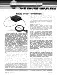
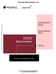
7.2 Physical Interface Connection
It is assumed that the MCU is connected to the CAN bus by means of the Physical Interface (CAN
transceiver). The MCU to CAN Physical Interface connection is shown in Figure 7-1
MCU
Physical Interface
TXCAN
Tx
RXCAN
Rx
Figure 7-1. Physical Interface Connection
For further required connection to the CAN transceiver refer to the CAN transceiver refernce manual.
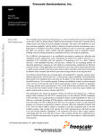
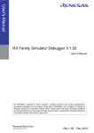
7.3 CAN Network Setup
There are couple of physical media which can be used for a CAN network implementation. The most
common CAN physical media is a 5V twisted pair media with differential signal transmission. An example
of a CAN high speed network implementation with twisted pair media is shown in Figure 7-2.
ECU
MCU
ECU
MCU
CAN
Transceiver
CAN
Transceiver
CAN-High
120 Ohm
120 Ohm
CAN-Low
Figure 7-2. High speed CAN network
MSCANS08 Driver User Manual, Rev. 0.1
Freescale Semiconductor
35
Building Application
For further information about CAN physical media refer to ISO11898 or to the CAN transceiver refernce
manual.
For a correct transmission of a CAM message two CAN nodes are required in a CAN network because the
transmitted CAN message has to be acknowledge. If a CAN message has not been acknowledged then the
sending node will re-send the message until an acknowledge has been detected.
7.4 Compilation
There are source files supplied with the library, which must be compiled:
Common files:
• Start08.c (start up code provided by CodeWarrior)
Application files:
• vector.c (vector table)
• myApp.c (application code)
msCAN Driver files:
• msCANdrvlite.c
• msCANgvlite.c
• msCANID.c
The recommended compiler versions are defined in the readme.txt file in the installation root
directory. If other versions are used, problems might arise.
7.5 Linking
The driver object files are linked to the rest of the application by including the object files. A file
containing startup code is also required.
7.5.1 CodeWarrior
To link the files properly the following segment should be defined:
• VECTORS_DATA — Segment for vector table.
• MSCAN_START — Start address of the msCAN register in memory map.
An example link file is shown below.
/* This is a linker parameter file for the MC9S08DZ60 */
NAMES END /* CodeWarrior will pass all the needed files to the linker by command line.
But here you may add your own files too. */
SEGMENTS /* here all RAM/ROM areas of the device are listed. Used in PLACEMENT below.
*/
MSCAN_START = NO_INIT
0x1880 TO 0x1880;
ROM
= READ_ONLY
0x1900 TO 0xFFBF;
MSCANS08 Driver User Manual, Rev. 0.1
36
Freescale Semiconductor
Linking
Z_RAM
RAM
ROM1
EEPROM
VECTORS
=
=
=
=
=
READ_WRITE
READ_WRITE
READ_ONLY
NO_INIT
READ_ONLY
0x0080
0x0100
0x1080
0x1400
0xFFC0
TO
TO
TO
TO
TO
0x00FF;
0x107F;
0x13FF;
0x17FF;
0xFFFF;
END
PLACEMENT /* here all predefined and user segments are placed into the SEGMENTS defined
above. */
MSCAN
INTO MSCAN_START;
DEFAULT_RAM
INTO RAM;
DEFAULT_ROM, ROM_VAR, STRINGS INTO ROM;/* ROM1 In case you want to use ROM1 as well,
be sure the option -OnB=b is passed to the compiler. */
ZeroSeg,
_DATA_ZEROPAGE, MY_ZEROPAGE
INTO Z_RAM;
VECTORS_DATA
INTO VECTORS;
END
STACKSIZE 0x50
ENTRIES
_vectab
END
MSCANS08 Driver User Manual, Rev. 0.1
Freescale Semiconductor
37
Building Application
MSCANS08 Driver User Manual, Rev. 0.1
38
Freescale Semiconductor
Linking
Appendix A
msCAN Driver Usage
A.1 Driver Initialization
The msCAN module must be initialised after a MCU reset by calling the driver API CAN_Init. This will
initialise the msCAN module with values specified in the file msCANdrv.h. After the function CAN_Init
has returned the msCAN module will synchronise to the CAN bus and will then be ready to participate in
CAN communication with other nodes. The data for initialising the msCAN module is defined in the file
msCANdrv.h.
A.2 Message Buffer Initialization and Configuration
This driver employs generic message buffers. Up to 32 message buffers may be defined. Each message
buffer must be configured by the application program before it can be used. Each message buffer consists
of the following elements:
Identifier Reference (1 byte)
Mode (1 byte)
Status (1 byte)
Data Length Code (1 byte)
Data (8 bytes)
Time Stamp (2 bytes, only if TIMESTAMP_CAN0 = TRUE)
Each message buffer thus requires 12 bytes of RAM without a time stamp, or 14 bytes of RAM with a time
stamp.
The driver function CAN_Init initialises the mode of all Message Buffers to CLOSED. Before a Message
Buffer can receive or transmit any messages, it must be configured by calling the function
CAN_ConfigMB. This function is used to specify a mode and a message Identifier for a particular
Message Buffer. Refer to Table 6-5 for the Message Buffer modes.
The Identifier is assigned to a Message Buffer by specifying the Identifier number from the list in the file
msCANID.h.
Tip: The speed efficiency of the receive ISR is improved by:
• using lower numbered Message Buffers to receive Data Frames,
• using the lowest numbered Message Buffers to receive the most frequent Data Frames.
Example
This snippet of code will initialise the msCAN module with the values defined in file msCANdrv.h. If there
are no errors, Message Buffers 0 to 7 are configured to receive Data Frames with Identifiers that match
Message Object Identifiers 0 to 7 and Message Buffers 8 to 15 are configured to transmit Data Frames with
Identifiers that match Message Object Identifiers 8 to 15.
UINT8 i;
MSCANS08 Driver User Manual, Rev. 0.1
Freescale Semiconductor
39
Building Application
/* init msCAN driver */
if(CAN_Init(FAST, 0) == ERR_OK)
{
for(i = 0; i < 8; i++)
{
/* Configure message buffers */
CAN_ConfigMB(i, RXDF, i, 0);
CAN_ConfigMB(i + 8, TXDF, i + 8, 0);
}
}
A.3 Transmitting a Data Frame
To transmit a Data Frame, a Message Buffer mode must first be configured to TXDF by calling the
function CAN_ConfigMB. This function also assigns the Identifier to the Message Buffer and sets the
status to NODATA. All Data Frames transmitted by this Message Buffer will have the Identifier assigned
at this stage (the Message Buffer may be reconfigured to transmit a different Identifier). Next, data must
be written into the Message Buffer by calling the function CAN_LoadMB. One of the arguments of this
function is an address where the data is to be copied from. This address must contain the DLC, and the
following addresses must contain the number of data bytes specified by the DLC. After the Message Buffer
has been loaded with data, the Message Buffer status is VALIDDATA. The Data Frame may now be
queued for transmission by calling the function CAN_TransmitMB, specifying the Message Buffer
number. Whilst it is queued for transmission, the Message Buffer status is QUEUED whilst waiting to be
transferred into a msCAN buffer, and QUEUED2 when it is in a msCAN buffer. When the Data Frame
has been transmitted successfully, the status of the Message Buffer changes to TRANSMITTED. This
Message Buffer may then be used to:
• Retransmit the original message, i.e. identical Identifier and data. Do this by calling
CAN_TransmitMB specifying the Message Buffer number.
• Transmit a new message with the original Identifier and new data. Do this by calling
CAN_LoadMB to load in new data, and then calling CAN_TransmitMB to transmit the new
message.
• Transmit a new message with a new Identifier and new data. Do this by calling CAN_ConfigMB
to specify a new Identifier number, then calling CAN_LoadMB to load in new data, and then calling
CAN_TransmitMB to transmit the new message.
A Message Buffer cannot be reconfigured or reloaded with data whilst it is queued for transmission, the
Frame must either be transmitted or the transmission aborted with the CAN_AbortMB function.
Note: When more than one Message Buffer is queued for transmission, the driver ensures that the message
with the greatest local priority in the queue is transmitted first. The local priority is defined by the
Identifier number (smallest Identifier number = greatest local priority).
Example
This snippet of code will configure Message Buffer 8 to transmit Data Frames. The Message Buffer is
loaded with 8 bytes of data (data[0] = 8) and if there are no errors, the Message Buffer is queued for
transmission.
UINT8 data[] = {8,7,6,5,4,3,2,1,0};
MSCANS08 Driver User Manual, Rev. 0.1
40
Freescale Semiconductor
Linking
/* config message buffer 8 */
CAN_ConfigMB(8, TXDF, 8, 0);
/* load data in message buffer 8 */
if(CAN_LoadMB(8, data, 0) == ERR_OK)
{
/* Transmit message buffer 8 */
CAN_TransmitMB(8, 0);
}
A.4 Receiving a Data Frame
To receive a Data Frame, a Message Buffer mode must first be configured to RXDF by calling the function
CAN_ConfigMB. This function also assigns the Identifier to the Message Buffer. This means that only
data from received messages which pass the acceptance filter and with an Identifier which matches the
Identifier assigned to a Message Buffer, will be stored in that Message Buffer. Initially, when configured
to RXDF, the status of the Message Buffer will be NODATA. When a message with a matching Identifier
is received, the driver will copy the data and DLC into the corresponding Message Buffer and the status
will be updated to NEWDATA. The data may now be read from the buffer by calling the function
CAN_ReadDataMB or CAN_ReadMB. After the data has been read, the status of the Message buffer
becomes READDATA until another new message is received. A Message Buffer of status READDATA
may be re-read. If a Message Buffer of status NEWDATA receives another message before it is read, the
new data will overwrite the previous data and the status of the Message Buffer becomes OVERRUN. Each
subsequent new message will overwrite the previous data, the status will remain at OVERRUN until the
Message Buffer is read.
Note: The speed efficiency of the receive ISR is improved by:
• using lower numbered Message Buffers to receive Data Frames,
• using the lowest numbered Message Buffers to receive the most frequent Data Frames.
Example
This snippet of code will configure Message Buffer 0 to receive Data Frames with an Identifier which
matches Message Object 0. The code then continuously attempts to read the Message Buffer in a loop until
the Message Buffer receives a Data Frame. When a Data Frame is received into the Message Buffer, the
CAN_ReadDataMB successfully reads the data.
UINT8 data[9];
/* Configure message buffer 0 */
CAN_ConfigMB(0, RXDF, 0, 0);
/* Wait until new data has been received in message buffer 0 */
while(CAN_ReadDataMB(0, data, 0) != ERR_OK);
MSCANS08 Driver User Manual, Rev. 0.1
Freescale Semiconductor
41
Building Application
A.5 Transmitting a Remote Frame
To transmit a Remote Frame, a Message Buffer mode must first be configured to TXRF by calling the
function CAN_ConfigMB. This function also assigns the Identifier to the Message Buffer. No data is
loaded into the Message Buffer as data is not transmitted by a Remote Frame. The Remote Frame is then
transmitted by calling the function CAN_TransmitMB, specifying the Message Buffer number. Whilst it
is queued for transmission, the Message Buffer status is QUEUED whilst waiting to be transferred into an
msCAN buffer, and QUEUED2 when it is in a msCAN buffer. When the Remote Frame has been
transmitted, the driver reconfigures the Message Buffer mode to RXDF and the status to NODATA. The
assigned Identifier is unchanged. This is so that the Message Buffer can be used to receive the Data Frame
expected as a reply to the Remote Frame.
Example
This snippet of code will configure Message Buffer 8 to transmit a Remote Frame. The code then
continuously attempt to read the Message Buffer in a loop until the Message Buffer receives a Data Frame
in reply to the Remote Frame. When a Data Frame is received into the Message Buffer, the
CAN_ReadDataMB successfully reads the data.
UINT8 data[9];
/* Configure message buffer 8 */
CAN_ConfigMB(8, TXRF, 8, 0);
/* transmit remote message */
CAN_TransmitMB(8, 0);
/* Wait until data has been received in message buffer 8 */
while(CAN_ReadDataMB(8, data, 0) != ERR_OK);
A.6 Automatic Reply to a Remote Frame
To configure a Message Buffer to automatically reply to Remote Frames, the function CAN_ConfigMB
is called with the argument AUTOTXDF as the specified mode and also specifying an Identifier number.
The Message Buffer must then be loaded with data by calling CAN_LoadMB. Now, when a Remote
Frame is received and accepted, and the Identifier matches the assigned Identifier of the AUTOTXDF
Message Buffer, that Message Buffer is automatically queued for transmission.
Example
This snippet of code will configure Message Buffer 8 to automatically transmit Data Frames in response
to received Remote Frames with an Identifier which matches Message Object 0.
UINT8 data[] = {8,7,6,5,4,3,2,1,0};
/* Configure message buffer 8 */
CAN_ConfigMB(8, AUTOTXDF, 8, 0);
/* Load message buffer 8 with data */
CAN_LoadMB(8, data, 0);
MSCANS08 Driver User Manual, Rev. 0.1
42
Freescale Semiconductor
Linking
A.7 Time Stamp
This driver is capable of storing a time stamp with each transmitted and received message. The time stamp
consists of a 16-bit timer value from a specific timer module. The exact timer module may vary between
MCU's. The time stamp value is captured at the end of the End Of Frame of a CAN message, i.e. at the
point at which if no errors have been detected, the message is considered valid. To enable time stamps, the
variable TIMESTAMP_CAN in file msCANdrv.h must be defined as TRUE. To read the time stamp value
for a particular Message Buffer, call the function CAN_ReadMB or CAN_ReadTimeMB.
A.8 Low Power Modes
In applications where low current consumption is important, it may be necessary to shut-down part or all
of the micro-controller during periods when no processing is required. There are different levels of reduced
power consumption: WAIT mode, STOP2 and STOP3 mode. These modes are entered by executing the
WAIT and STOP instructions respectively. Normal processing is resumed when a reset or an interrupt
occurs. For the diffrences between STOP2 and STOP3 modes check the MCU reference manual.
SLEEP mode is a low power mode which applies to the msCAN module only and is independent of the
MCU mode. In SLEEP mode, the msCAN is shut down in a controlled manner. Transmission and
reception of CAN messages is halted. However, the CANRX input pin remains active and if a transition
is detected on the CAN bus the msCAN module will wake-up and function normally after 11 recessive bits
have been detected. A CAN message which wakes up the msCAN module is therefore not received or
acknowledged, but the next message is (unless the MCU was in STOP mode). The msCAN is requested
to enter SLEEP mode by calling the function CAN_Sleep. The function CAN_CheckStatus should be
used to verify that the msCAN has entered SLEEP mode. The msCAN is woken up from SLEEP mode
either by detecting a transition on the CAN bus or by calling the function CAN_Wakeup or
CAN_TransmitMB. In the case when the msCAN is woken up by a transition on the CAN bus, this will
also wake up the MCU from WAIT mode or STOP3 mode but not from STOP2 mode. The msCAN has a
wake-up filter which may be used to limit the minimum transition period which will wake-up the msCAN.
This is activated by the WU_FILTER_CAN variable in the file msCANdrv.h
In WAIT mode, the CPU and certain other peripheral modules are not clocked, i.e. no longer function.
Some modules may be programmable to function or not in WAIT mode. The msCANS08 may be
programmed to function or not in WAIT mode by means of the CSWAI bit, which is controlled by the
CSWAI_CAN variable in the file msCANdrv.h. In both cases, the msCANS08 may be put in SLEEP
mode prior to entering WAIT mode (in the case of msCAN not clocked in WAIT mode, it is recommended
to put the msCANS08 in SLEEP mode prior to entering WAIT mode). If the msCAN is put into SLEEP
mode prior to entering WAIT mode, then a transition on the CAN bus will also wake up the MCU from
WAIT mode.
In STOP3 mode, the MCU oscillator is shut down and so no modules are clocked. Note that it may take a
significant period of time (100's of microseconds or milliseconds, depending on the crystal) for the MCU
to recover from STOP3 mode due to the start-up time of the oscillator. No CAN messages can be received
during this time. It is recommended to put the msCAN in SLEEP mode prior to entering STOP3 mode. If
the msCAN is put into SLEEP mode prior to entering STOP3 mode, then a transition on the CAN bus will
also wake up the MCU from STOP3 mode.
MSCANS08 Driver User Manual, Rev. 0.1
Freescale Semiconductor
43
Building Application
In STOP2 mode, the MCU oscillator is shut down and so no modules are clocked. furthermore all pin are
latched to the state prior entering STOP2 mode. The msCAN cannot wake up the MCU from STOP2 in
any cases since the msCAN is in powerdown mode during the MCU is in STOP2 mode.
A.9 Reserved Keywords
M_Identifier_CAN
NO_OF_MB_CAN
ID_CODE0_CAN
M_IdentifierType_CAN
NO_OF_ID_CAN
ID_CODE1_CAN
BufferStatus_CAN
TIMESTAMP_CAN
ID_CODE2_CAN
BufferDLC_CAN
CLKSRC_CAN
ID_CODE3_CAN
BufferData_CAN
PRESCALER_CAN
ID_CODE4_CAN
BufferTimeStamp_CAN
PROP_SEG_CAN
ID_CODE5_CAN
msCANStart
PHASE_SEG1_CAN
ID_CODE6_CAN
NoOfMB
PHASE_SEG2_CAN
ID_CODE7_CAN
NoOfID
RJW_CAN
ID_MASK0_CAN
TimeStampOption
LISTEN_CAN
ID_MASK1_CAN
CMCR0_Def
CANENABLE_CAN
ID_MASK2_CAN
CMCR1_Def
SAMPLEX3_CAN
ID_MASK3_CAN
CBTR0_Def
CSWAI_CAN
ID_MASK4_CAN
CBTR1_Def
WU_ENABLE_CAN
ID_MASK5_CAN
CIDAC_Def
CMCR0_CAN
ID_MASK6_CAN
CID_FilterDef
CMCR1_CAN
ID_MASK7_CAN
CBTR0_CAN
MOx_ID_TYPE_CAN
CBTR1_CAN
MOx_ID_CAN
WU_FILTER_CAN
ACC_FILTER_CAN
MOx_IDR_CAN
MSCANS08 Driver User Manual, Rev. 0.1
44
Freescale Semiconductor
Linking
Appendix B
Sample Application
B.1 Sample Description
B.2 Sample Building and Running
To build the sample, CodeWarrior software should be installed on the computer. For supported compiler
and debugger versions, refer to the readme.txt file in the sample directory.
B.3 CodeWarrior Project
The sample comes with a CodeWarrior project that allows simple access to all files and ready configured
code generation settings.
The project is called sample.mcp.
MSCANS08 Driver User Manual, Rev. 0.1
Freescale Semiconductor
45
Building Application
MSCANS08 Driver User Manual, Rev. 0.1
46
Freescale Semiconductor
Linking
Appendix C Further Information
C.1 Application Notes
Following Application notes are useful during developing a CAN application:
• AN2283 — Freescale Scalable Controller Area Networks (msCAN) Interrupts
• AN1798 — CAN Bit Timing Requirements
• AN2255 — MSCAN low Power Applications
C.2 Online Training
Freescale msCANS08 Online Training is available on www.freescale.com
MSCANS08 Driver User Manual, Rev. 0.1
Freescale Semiconductor
47
Building Application
MSCANS08 Driver User Manual, Rev. 0.1
48
Freescale Semiconductor
Linking
Appendix D
Performance Characteristics
D.1 Performance Characteristics
D.2 Memory Consumption
MSCANS08 Driver User Manual, Rev. 0.1
Freescale Semiconductor
49
Building Application
MSCANS08 Driver User Manual, Rev. 0.1
50
Freescale Semiconductor
How to Reach Us:
Home Page:
www.freescale.com
E-mail:
[email protected]
USA/Europe or Locations Not Listed:
Freescale Semiconductor
Technical Information Center, CH370
1300 N. Alma School Road
Chandler, Arizona 85224
+1-800-521-6274 or +1-480-768-2130
[email protected]
Europe, Middle East, and Africa:
Freescale Halbleiter Deutschland GmbH
Technical Information Center
Schatzbogen 7
81829 Muenchen, Germany
+44 1296 380 456 (English)
+46 8 52200080 (English)
+49 89 92103 559 (German)
+33 1 69 35 48 48 (French)
[email protected]
Japan:
Freescale Semiconductor Japan Ltd.
Headquarters
ARCO Tower 15F
1-8-1, Shimo-Meguro, Meguro-ku,
Tokyo 153-0064, Japan
0120 191014 or +81 3 5437 9125
[email protected]
Asia/Pacific:
Freescale Semiconductor Hong Kong Ltd.
Technical Information Center
2 Dai King Street
Tai Po Industrial Estate
Tai Po, N.T., Hong Kong
+800 2666 8080
[email protected]
For Literature Requests Only:
Freescale Semiconductor Literature Distribution Center
P.O. Box 5405
Denver, Colorado 80217
1-800-441-2447 or 303-675-2140
Fax: 303-675-2150
[email protected]
Information in this document is provided solely to enable system and
software implementers to use Freescale Semiconductor products. There are
no express or implied copyright licenses granted hereunder to design or
fabricate any integrated circuits or integrated circuits based on the
information in this document.
Freescale Semiconductor reserves the right to make changes without further
notice to any products herein. Freescale Semiconductor makes no warranty,
representation or guarantee regarding the suitability of its products for any
particular purpose, nor does Freescale Semiconductor assume any liability
arising out of the application or use of any product or circuit, and specifically
disclaims any and all liability, including without limitation consequential or
incidental damages. “Typical” parameters that may be provided in Freescale
Semiconductor data sheets and/or specifications can and do vary in different
applications and actual performance may vary over time. All operating
parameters, including “Typicals”, must be validated for each customer
application by customer’s technical experts. Freescale Semiconductor does
not convey any license under its patent rights nor the rights of others.
Freescale Semiconductor products are not designed, intended, or authorized
for use as components in systems intended for surgical implant into the body,
or other applications intended to support or sustain life, or for any other
application in which the failure of the Freescale Semiconductor product could
create a situation where personal injury or death may occur. Should Buyer
purchase or use Freescale Semiconductor products for any such unintended
or unauthorized application, Buyer shall indemnify and hold Freescale
Semiconductor and its officers, employees, subsidiaries, affiliates, and
distributors harmless against all claims, costs, damages, and expenses, and
reasonable attorney fees arising out of, directly or indirectly, any claim of
personal injury or death associated with such unintended or unauthorized
use, even if such claim alleges that Freescale Semiconductor was negligent
regarding the design or manufacture of the part.
Freescale™ and the Freescale logo are trademarks of Freescale
Semiconductor, Inc. All other product or service names are the property
of their respective owners.
© Freescale Semiconductor, Inc. 2005-2007. All rights reserved.
MSCANS08DUM
Rev. 0.1
03/2007