1
Freescale Semiconductor, Inc.
ARCHIVED BY FREESCALE SEMICONDUCTOR, INC. 2005
Freescale Semiconductor, Inc...
ARCHIVED BY FREESCALE SEMICONDUCTOR, INC. 2005
Embedded SDK
(Software Development Kit)
DSP56800/MSCAN Driver User’s Manual
SDK116/D
Rev. 2, 07/22/2002
© Motorola, Inc., 2002. All rights reserved.
For More Information On This Product,
Go to: www.freescale.com
Freescale Semiconductor, Inc.
ARCHIVED BY FREESCALE SEMICONDUCTOR, INC. 2005
Freescale Semiconductor, Inc...
ARCHIVED BY FREESCALE SEMICONDUCTOR, INC. 2005
For More Information On This Product,
Go to: www.freescale.com
Freescale Semiconductor, Inc.
ARCHIVED BY FREESCALE SEMICONDUCTOR, INC. 2005
Contents
Audience . . . . . . . . . . . . . . . . . . . . . . . . . . . . . . . . . . . . . . . . . . . . . . . . . . . . . . . . . ix
Organization . . . . . . . . . . . . . . . . . . . . . . . . . . . . . . . . . . . . . . . . . . . . . . . . . . . . . . ix
Suggested Reading . . . . . . . . . . . . . . . . . . . . . . . . . . . . . . . . . . . . . . . . . . . . . . . . . ix
Conventions . . . . . . . . . . . . . . . . . . . . . . . . . . . . . . . . . . . . . . . . . . . . . . . . . . . . . . . x
Definitions, Acronyms, and Abbreviations . . . . . . . . . . . . . . . . . . . . . . . . . . . . . . . x
References. . . . . . . . . . . . . . . . . . . . . . . . . . . . . . . . . . . . . . . . . . . . . . . . . . . . . . . . xi
ARCHIVED BY FREESCALE SEMICONDUCTOR, INC. 2005
Freescale Semiconductor, Inc...
About This Document
Chapter 1
Overview
1.1
Introduction. . . . . . . . . . . . . . . . . . . . . . . . . . . . . . . . . . . . . . . . . . . . . . . . . . . . . . . 1-1
1.1.1
Driver Features . . . . . . . . . . . . . . . . . . . . . . . . . . . . . . . . . . . . . . . . . . . . . . . . . 1-1
1.2
CAN Overview . . . . . . . . . . . . . . . . . . . . . . . . . . . . . . . . . . . . . . . . . . . . . . . . . . . . 1-1
1.3
MSCAN Overview . . . . . . . . . . . . . . . . . . . . . . . . . . . . . . . . . . . . . . . . . . . . . . . . . 1-3
1.3.1
Message Transmission . . . . . . . . . . . . . . . . . . . . . . . . . . . . . . . . . . . . . . . . . . . 1-4
1.3.2
Message Receiving . . . . . . . . . . . . . . . . . . . . . . . . . . . . . . . . . . . . . . . . . . . . . . 1-4
1.4
MSCAN Driver Overview . . . . . . . . . . . . . . . . . . . . . . . . . . . . . . . . . . . . . . . . . . . 1-5
Chapter 2
MSCAN Driver Description
2.1
MSCAN Driver Functionality Overview . . . . . . . . . . . . . . . . . . . . . . . . . . . . . . . .2-1
2.2
MSCAN Driver Static Configuration . . . . . . . . . . . . . . . . . . . . . . . . . . . . . . . . . . . 2-2
2.3
Application Static Configuration . . . . . . . . . . . . . . . . . . . . . . . . . . . . . . . . . . . . . . 2-3
2.3.1
CAN_MAX_RECEIVE_ID . . . . . . . . . . . . . . . . . . . . . . . . . . . . . . . . . . . . . . . 2-3
2.3.2
CAN_MAX_TRANSMIT_ID . . . . . . . . . . . . . . . . . . . . . . . . . . . . . . . . . . . . . 2-3
2.3.3
CAN_SPEED . . . . . . . . . . . . . . . . . . . . . . . . . . . . . . . . . . . . . . . . . . . . . . . . . . 2-3
2.3.4
CAN_TIME_SEGMENT1 . . . . . . . . . . . . . . . . . . . . . . . . . . . . . . . . . . . . . . . . 2-4
2.3.5
CAN_TIME_SEGMENT2 . . . . . . . . . . . . . . . . . . . . . . . . . . . . . . . . . . . . . . . . 2-4
2.3.6
CAN_PRESCALER . . . . . . . . . . . . . . . . . . . . . . . . . . . . . . . . . . . . . . . . . . . . . 2-4
2.3.7
CAN_SAMPLING . . . . . . . . . . . . . . . . . . . . . . . . . . . . . . . . . . . . . . . . . . . . . . 2-4
2.3.8
CAN_SYNCH_JUMP_WIDTH . . . . . . . . . . . . . . . . . . . . . . . . . . . . . . . . . . . . 2-4
2.3.9
CAN_STOP_IN_WAIT_MODE . . . . . . . . . . . . . . . . . . . . . . . . . . . . . . . . . . . 2-5
2.3.10
CAN_LOOP_BACK . . . . . . . . . . . . . . . . . . . . . . . . . . . . . . . . . . . . . . . . . . . . 2-5
2.3.11
CAN_WAKE_UP_MODE . . . . . . . . . . . . . . . . . . . . . . . . . . . . . . . . . . . . . . . . 2-5
2.3.12
CAN_CLOCK_SOURCE. . . . . . . . . . . . . . . . . . . . . . . . . . . . . . . . . . . . . . . . . 2-5
2.3.13
CAN_CUSTOM_FILTER_CODE. . . . . . . . . . . . . . . . . . . . . . . . . . . . . . . . . . 2-5
2.3.14
CAN_CUSTOM_FILTER_MASK . . . . . . . . . . . . . . . . . . . . . . . . . . . . . . . . .2-6
2.3.15
CAN_RECEIVE_ID_QUEUE_SIZE. . . . . . . . . . . . . . . . . . . . . . . . . . . . . . . .2-6
2.3.16
CAN_RAW_CALLBACK . . . . . . . . . . . . . . . . . . . . . . . . . . . . . . . . . . . . . . . . 2-6
MOTOROLA
Table of Contents
For More Information On This Product,
Go to: www.freescale.com
iii
Freescale Semiconductor, Inc.
ARCHIVED BY FREESCALE SEMICONDUCTOR, INC. 2005
Freescale Semiconductor, Inc...
ARCHIVED BY FREESCALE SEMICONDUCTOR, INC. 2005
2.4
Low-Power Modes . . . . . . . . . . . . . . . . . . . . . . . . . . . . . . . . . . . . . . . . . . . . . . . . . 2-7
2.5
MSCAN Driver Files . . . . . . . . . . . . . . . . . . . . . . . . . . . . . . . . . . . . . . . . . . . . . . . 2-8
2.6
Application Files. . . . . . . . . . . . . . . . . . . . . . . . . . . . . . . . . . . . . . . . . . . . . . . . . . . 2-9
2.7
Application Data Types . . . . . . . . . . . . . . . . . . . . . . . . . . . . . . . . . . . . . . . . . . . . 2-10
2.7.1
can_sOpenParams . . . . . . . . . . . . . . . . . . . . . . . . . . . . . . . . . . . . . . . . . . . . . . 2-10
2.7.2
can_eFormat . . . . . . . . . . . . . . . . . . . . . . . . . . . . . . . . . . . . . . . . . . . . . . . . . . 2-10
2.7.3
can_eScheduleType . . . . . . . . . . . . . . . . . . . . . . . . . . . . . . . . . . . . . . . . . . . . 2-10
2.7.4
can_sData . . . . . . . . . . . . . . . . . . . . . . . . . . . . . . . . . . . . . . . . . . . . . . . . . . . . 2-11
2.8
Driver Memory Requirements . . . . . . . . . . . . . . . . . . . . . . . . . . . . . . . . . . . . . . . 2-11
2.8.1
MSCAN Driver Code . . . . . . . . . . . . . . . . . . . . . . . . . . . . . . . . . . . . . . . . . . . 2-11
2.8.1.1
Unqueued Transmission Mode, 11-bit Standard Addressing Type:. . . . . 2-11
2.8.1.2
Unqueued Transmission Mode, 29-bit Extended Addressing Type: . . . . 2-11
2.8.1.3
Queued Transmission Mode, 11-bit Standard Addressing Type:. . . . . . . 2-12
2.8.1.4
Queued Transmission Mode, 29-bit Extended Addressing Type: . . . . . . 2-12
2.8.2
MSCAN Driver Simple Application Code . . . . . . . . . . . . . . . . . . . . . . . . . . . 2-12
Chapter 3
API Functional Description
3.1
3.1.1
3.2
3.2.1
3.2.2
3.2.3
3.2.4
3.2.5
3.3
3.3.1
3.3.2
3.3.3
3.3.4
3.4
3.4.1
3.4.2
3.4.3
3.4.4
3.4.5
3.5
3.5.1
3.5.2
3.5.3
3.5.4
3.5.5
3.6
3.6.1
3.6.2
3.6.3
iv
Overview. . . . . . . . . . . . . . . . . . . . . . . . . . . . . . . . . . . . . . . . . . . . . . . . . . . . . . . . . 3-1
Error Codes . . . . . . . . . . . . . . . . . . . . . . . . . . . . . . . . . . . . . . . . . . . . . . . . . . . . 3-1
open API statement . . . . . . . . . . . . . . . . . . . . . . . . . . . . . . . . . . . . . . . . . . . . . . . . . 3-1
Prototype . . . . . . . . . . . . . . . . . . . . . . . . . . . . . . . . . . . . . . . . . . . . . . . . . . . . . . 3-1
Arguments Description . . . . . . . . . . . . . . . . . . . . . . . . . . . . . . . . . . . . . . . . . . . 3-2
Return Values and Error Codes . . . . . . . . . . . . . . . . . . . . . . . . . . . . . . . . . . . . 3-2
Functionality Description . . . . . . . . . . . . . . . . . . . . . . . . . . . . . . . . . . . . . . . . . 3-2
Example . . . . . . . . . . . . . . . . . . . . . . . . . . . . . . . . . . . . . . . . . . . . . . . . . . . . . . 3-3
close API statement . . . . . . . . . . . . . . . . . . . . . . . . . . . . . . . . . . . . . . . . . . . . . . . . 3-4
Prototype . . . . . . . . . . . . . . . . . . . . . . . . . . . . . . . . . . . . . . . . . . . . . . . . . . . . . . 3-4
Arguments Description . . . . . . . . . . . . . . . . . . . . . . . . . . . . . . . . . . . . . . . . . . . 3-4
Return Values and Error Codes . . . . . . . . . . . . . . . . . . . . . . . . . . . . . . . . . . . . 3-4
Functionality Description . . . . . . . . . . . . . . . . . . . . . . . . . . . . . . . . . . . . . . . . . 3-4
read API statement . . . . . . . . . . . . . . . . . . . . . . . . . . . . . . . . . . . . . . . . . . . . . . . . . 3-4
Prototype . . . . . . . . . . . . . . . . . . . . . . . . . . . . . . . . . . . . . . . . . . . . . . . . . . . . . . 3-4
Arguments Description . . . . . . . . . . . . . . . . . . . . . . . . . . . . . . . . . . . . . . . . . . . 3-4
Return Values and Error Codes . . . . . . . . . . . . . . . . . . . . . . . . . . . . . . . . . . . . 3-5
Functionality Description . . . . . . . . . . . . . . . . . . . . . . . . . . . . . . . . . . . . . . . . . 3-5
Example . . . . . . . . . . . . . . . . . . . . . . . . . . . . . . . . . . . . . . . . . . . . . . . . . . . . . . 3-5
write API statement . . . . . . . . . . . . . . . . . . . . . . . . . . . . . . . . . . . . . . . . . . . . . . . . 3-6
Prototype . . . . . . . . . . . . . . . . . . . . . . . . . . . . . . . . . . . . . . . . . . . . . . . . . . . . . . 3-6
Arguments Description . . . . . . . . . . . . . . . . . . . . . . . . . . . . . . . . . . . . . . . . . . . 3-6
Return Values and Error Codes . . . . . . . . . . . . . . . . . . . . . . . . . . . . . . . . . . . . 3-6
Functionality Description . . . . . . . . . . . . . . . . . . . . . . . . . . . . . . . . . . . . . . . . . 3-7
Example . . . . . . . . . . . . . . . . . . . . . . . . . . . . . . . . . . . . . . . . . . . . . . . . . . . . . . 3-7
ioctl API statement . . . . . . . . . . . . . . . . . . . . . . . . . . . . . . . . . . . . . . . . . . . . . . . . . 3-8
Prototype . . . . . . . . . . . . . . . . . . . . . . . . . . . . . . . . . . . . . . . . . . . . . . . . . . . . . . 3-8
Arguments Description . . . . . . . . . . . . . . . . . . . . . . . . . . . . . . . . . . . . . . . . . . . 3-8
Return Values and Error Codes . . . . . . . . . . . . . . . . . . . . . . . . . . . . . . . . . . . . 3-8
DSP56800/MSCAN Driver User Manual
For More Information On This Product,
Go to: www.freescale.com
MOTOROLA
Freescale Semiconductor, Inc.
ARCHIVED BY FREESCALE SEMICONDUCTOR, INC. 2005
3.6.4
3.6.5
Functionality Description . . . . . . . . . . . . . . . . . . . . . . . . . . . . . . . . . . . . . . . . . 3-9
Example . . . . . . . . . . . . . . . . . . . . . . . . . . . . . . . . . . . . . . . . . . . . . . . . . . . . . 3-10
Chapter 4
License
4.1
Limited Use License Agreement . . . . . . . . . . . . . . . . . . . . . . . . . . . . . . . . . . . . . . 4-1
ARCHIVED BY FREESCALE SEMICONDUCTOR, INC. 2005
Freescale Semiconductor, Inc...
Appendix A
Demo Application
A.1
A.2
A.3
A.4
A.5
CAN Test Application . . . . . . . . . . . . . . . . . . . . . . . . . . . . . . . . . . . . . . . . . . . . .
CAN Bus Installation . . . . . . . . . . . . . . . . . . . . . . . . . . . . . . . . . . . . . . . . . . . . . .
Demo Overview . . . . . . . . . . . . . . . . . . . . . . . . . . . . . . . . . . . . . . . . . . . . . . . . . .
DSP5680x Demo Description. . . . . . . . . . . . . . . . . . . . . . . . . . . . . . . . . . . . . . . .
PC Demo Description . . . . . . . . . . . . . . . . . . . . . . . . . . . . . . . . . . . . . . . . . . . . . .
A-1
A-1
A-2
A-2
A-3
Appendix B
DSP56800/MSCAN Hardware Notes
B.1
Allowed Time Segments Settings. . . . . . . . . . . . . . . . . . . . . . . . . . . . . . . . . . . . . B-1
MOTOROLA
Table of Contents
For More Information On This Product,
Go to: www.freescale.com
v
Freescale Semiconductor, Inc.
ARCHIVED BY FREESCALE SEMICONDUCTOR, INC. 2005
Freescale Semiconductor, Inc...
ARCHIVED BY FREESCALE SEMICONDUCTOR, INC. 2005
vi
DSP56800/MSCAN Driver User Manual
For More Information On This Product,
Go to: www.freescale.com
MOTOROLA
Freescale Semiconductor, Inc.
ARCHIVED BY FREESCALE SEMICONDUCTOR, INC. 2005
ARCHIVED BY FREESCALE SEMICONDUCTOR, INC. 2005
Freescale Semiconductor, Inc...
List of Tables
Table 3-1
Table 3-2
Table 3-3
Table 3-4
Table 3-5
Table 3-6
Table 3-7
Table 3-8
Table A-1
Table B-1
Table B-2
MOTOROLA
Error Codes . . . . . . . . . . . . . . . . . . . . . . . . . . . . . . . . . . . . . . . . . . . . . . . . . . . . . 3-1
open Statement Parameters . . . . . . . . . . . . . . . . . . . . . . . . . . . . . . . . . . . . . . . . . 3-2
close Statement Parameters . . . . . . . . . . . . . . . . . . . . . . . . . . . . . . . . . . . . . . . . 3-4
Read Statement Parameters . . . . . . . . . . . . . . . . . . . . . . . . . . . . . . . . . . . . . . . . 3-5
write Statement Parameters . . . . . . . . . . . . . . . . . . . . . . . . . . . . . . . . . . . . . . . . 3-6
ioctl Statement Parameters . . . . . . . . . . . . . . . . . . . . . . . . . . . . . . . . . . . . . . . . . 3-8
MSCAN Status Flags . . . . . . . . . . . . . . . . . . . . . . . . . . . . . . . . . . . . . . . . . . . . . 3-9
Message Buffer Status Values . . . . . . . . . . . . . . . . . . . . . . . . . . . . . . . . . . . . . 3-10
Pin Descriptions . . . . . . . . . . . . . . . . . . . . . . . . . . . . . . . . . . . . . . . . . . . . . . . . . A-2
DSP56800/MSCAN Related Parameters to Assign CAN Speed Manually . . . . B-1
Allowed DSP56800 CAN Speed Related Parameters . . . . . . . . . . . . . . . . . . . . B-2
List of Tables
For More Information On This Product,
Go to: www.freescale.com
vii
Freescale Semiconductor, Inc.
ARCHIVED BY FREESCALE SEMICONDUCTOR, INC. 2005
Freescale Semiconductor, Inc...
ARCHIVED BY FREESCALE SEMICONDUCTOR, INC. 2005
viii
DSP56800/MSCAN Driver User Manual
For More Information On This Product,
Go to: www.freescale.com
MOTOROLA
Freescale Semiconductor, Inc.
ARCHIVED BY FREESCALE SEMICONDUCTOR, INC. 2005
List of Figures
MSCAN Message Buffers Organization . . . . . . . . . . . . . . . . . . . . . . . . . . . . . . 1-4
CAN Bus. . . . . . . . . . . . . . . . . . . . . . . . . . . . . . . . . . . . . . . . . . . . . . . . . . . . . . . A-1
Demo Application Main Dialog Window. . . . . . . . . . . . . . . . . . . . . . . . . . . . . . A-3
ARCHIVED BY FREESCALE SEMICONDUCTOR, INC. 2005
Freescale Semiconductor, Inc...
Figure 1-1
Figure A-1
Figure A-2
MOTOROLA
List of Figures
For More Information On This Product,
Go to: www.freescale.com
ix
Freescale Semiconductor, Inc.
ARCHIVED BY FREESCALE SEMICONDUCTOR, INC. 2005
Freescale Semiconductor, Inc...
ARCHIVED BY FREESCALE SEMICONDUCTOR, INC. 2005
x
DSP56800/MSCAN Driver User Manual
For More Information On This Product,
Go to: www.freescale.com
MOTOROLA
Freescale Semiconductor, Inc.
ARCHIVED BY FREESCALE SEMICONDUCTOR, INC. 2005
About This Document
This manual describes the DSP56800/MSCAN Driver application for use with the Embedded Software
Development Kit, (SDK).
ARCHIVED BY FREESCALE SEMICONDUCTOR, INC. 2005
Freescale Semiconductor, Inc...
Audience
This manual targets software developers implementing Controller Area Network protocol driver routines
within software applications.
Organization
This User’s Manual consists of the following sections:
•
•
•
•
•
•
Chapter 1, Overview describes general features of the Controller Area Network (CAN), the
Motorola Scalable Controller Area Network (MSCAN), and the MSCAN driver.
Chapter 2, MSCAN Driver Description describes MSCAN driver functionality as well as the
MSCAN driver and driver application configuration in the framework of the Motorola Embedded
SDK.
Chapter 3, API Functional Description describes MSCAN driver API statements.
Chapter 4, License provides the license required to use this product
Appendix A Demo Application contains the description of the Demo application provided with
the MSCAN Driver to demonstrate its operation.
Appendix B DSP56800/MSCAN Hardware Notes describes settings and parameters for the
MSCAN.
Suggested Reading
We recommend that you have a copy of the following references:
•
•
•
DSP56800 Family Manual, DSP56800FM/AD
DSP56824 User’s Manual, DSP56824UM/AD
Inside CodeWarrior: Core Tools, Metrowerks Corp.
MOTOROLA
Preface
For More Information On This Product,
Go to: www.freescale.com
xi
Freescale Semiconductor, Inc.
ARCHIVED BY FREESCALE SEMICONDUCTOR, INC. 2005
Conventions
This document uses the following notational conventions:
ARCHIVED BY FREESCALE SEMICONDUCTOR, INC. 2005
Freescale Semiconductor, Inc...
Typeface,
Symbol or Term
Meaning
Examples
Courier
Monospaced
Type
Code examples
//Process command for line flash
Italic
Directory names,
project names,
calls,
functions,
statements,
procedures,
routines,
arguments,
file names,
applications,
variables,
directives,
code snippets
in text
...and contains these core directories:
applications contains applications software...
Bold
Reference sources,
paths,
emphasis
...refer to the Targeting DSP56F80x Platform
manual....
...see: C:\Program Files\Motorola\Embedded
SDK\help\tutorials
Blue Text
Linkable on-line
...refer to Chapter 7, License....
Number
Any number is considered a positive value,
unless preceded by a
minus symbol to signify
a negative value
3V
-10
DES-1
ALL CAPITAL
LETTERS
# defines/
defined constants
# define INCLUDE_STACK_CHECK
Brackets [...]
Function keys
...by pressing function key [F7]
Quotation
marks, “...”
Returned messages
...the message, “Test Passed” is displayed....
...CodeWarrior project, 3des.mcp is...
...the pConfig argument....
...defined in the C header file, aec.h....
...if unsuccessful for any reason, it will return
“NULL”...
Definitions, Acronyms, and Abbreviations
The following list defines the acronyms and abbreviations used in this document. As this template
develops, this list will be generated from the document. As we develop more group resources, these
acronyms will be easily defined from a common acronym dictionary. Please note that while the acronyms
are in solid caps, terms in the definition should be initial capped ONLY IF they are trademarked names or
proper nouns.
xii
DSP56800/MSCAN Driver User Manual
For More Information On This Product,
Go to: www.freescale.com
MOTOROLA
Freescale Semiconductor, Inc.
ARCHIVED BY FREESCALE SEMICONDUCTOR, INC. 2005
Application Program Interface
ARCHIVED BY FREESCALE SEMICONDUCTOR, INC. 2005
Freescale Semiconductor, Inc...
API
CAN
Controller Area Network
CAN ID
CAN Identifier
DLC
Data Length Code
DSP
Digital Signal Processor or Digital Signal Processing
IDE
Identifier Extension
ISR
Interrupt Service Routine
MCU
MicroController Unit
MSCAN
Motorola Scalable Controller Area Network
RAM
Random Access (read/write) Memory
ROM
Read Only Memory
RTR
Remote Transmission Request
SDK
Software Development Kit
SRR
Substitute Remote Request
References
The following sources were used to produce this book:
1.
2.
3.
4.
5.
DSP56800 Family Manual, DSP56800FM/D
DSP56824 User’s Manual, DSP56824UM/D
DSP56F80x User’s Manual, DSP56F801_7UM/D
CAN Specifications, Version 2.0, Phillips Semiconductors, 1991
Embedded SDK Programmer’s Guide
MOTOROLA
Preface
For More Information On This Product,
Go to: www.freescale.com
xiii
Freescale Semiconductor, Inc.
ARCHIVED BY FREESCALE SEMICONDUCTOR, INC. 2005
Freescale Semiconductor, Inc...
ARCHIVED BY FREESCALE SEMICONDUCTOR, INC. 2005
xiv
DSP56800/MSCAN Driver User Manual
For More Information On This Product,
Go to: www.freescale.com
MOTOROLA
Freescale Semiconductor, Inc.
ARCHIVED BY FREESCALE SEMICONDUCTOR, INC. 2005
1.1 Introduction
ARCHIVED BY FREESCALE SEMICONDUCTOR, INC. 2005
Freescale Semiconductor, Inc...
Chapter 1
Overview
The Motorola Scalable Controller Area Network, (MSCAN), driver described in this manual is provided as
a part of Motorola’s Embedded Software Development Kit (SDK) package for DSP56803/05 and is
intended to be used within this package.
This document describes Controller Area Network, (CAN), protocol driver routines for the Motorola
DSP56803/05 MSCAN modules. The Driver Application Programming Interface, (API), is a set of
high-level functions accessed via the standard SDK API.
The DSP56800/MSCAN Driver is provided in source code and a demo application to present the use of
driver routines. The Metrowerks’ C compiler is used as a target compiler.
Please refer to the standard Software License Agreement in Chapter 4 for license terms and conditions;
please consult with your Motorola representative for premium product licensing.
1.1.1 Driver Features
•
•
•
•
•
•
•
•
•
•
Configurable initial settings for MSCAN registers
Configurable number of message buffers for both send and receive
Time scheduled and priority scheduled message transmission
Configurable synchronous and asynchronous operating mode
Configurable received messages queue for every receiving buffer
Possibility to specify user’s call back function for receiving, to speed up/customize the ReceiveISR
The driver automatically assigns Acceptance Filters
Sleep and Wake-up functions
Static driver configuration can set either CAN2.0A or CAN2.0B addressing modes
Static driver configuration can set either queued or unqueued message transmission types
MOTOROLA
Overview
For More Information On This Product,
Go to: www.freescale.com
1-1
Overview
Freescale Semiconductor, Inc.
ARCHIVED BY FREESCALE SEMICONDUCTOR, INC. 2005
1.2 CAN Overview
The CAN was originally developed by BOSCH Gmbh as a serial communications protocol to pass
information between controllers on an automotive network and thus reduce the growing complexity of the
wiring harness in modern car design. The benefits of the CAN protocol are applicable to other
cost-sensitive and environmentally demanding applications in the industrial sector. The low cost of CAN
networks is realized by high-performance microcontrollers with on-chip CAN modules.
CAN is a Carrier Sense Multiple Access with Collision Detection, (CSMA/CD), protocol. Information is
transmitted on the CAN bus in fixed format messages by nodes. The main message formats are called:
ARCHIVED BY FREESCALE SEMICONDUCTOR, INC. 2005
Freescale Semiconductor, Inc...
The driver routines described in this User Manual are designed to facilitate the use of Motorola
DSP56803/05 on-chip MSCAN modules Because the application programmer does not need an
understanding of the modules’ detailed operation to develop effective applications. However, a basic
understanding of the CAN protocol is assumed and a very brief overview is provided here.
•
•
•
Data Frame, used to transmit data and consisting of:
— Start bit
— Arbitration field
— Control field
— Data field
— Cyclic Redundancy (CRC) Field
— Acknowledge field
— End-of-frame field
Remote Transmission Request Frame (Remote Frame), a request for data
Error Frame, transmitted automatically by the MSCAN module when an error is detected
A Remote Frame is similar to a Data Frame but has no data field. To transmit a Data Frame, the application
must specify the arbitration field, a part of the control field, (Data Length Code, from 0 to 8) and the data
field, (number of bytes specified by Data Length Code); the other fields are generated automatically by the
CAN controller.
The arbitration field contains the message Identifier, which has three functions:
1. It defines the priority of the message. CAN is a multi-master protocol; when more than one
node is attempting to start the transmission of Data or Remote Frames simultaneously, the
bus access conflict is resolved by bit-wise arbitration, using the arbitration field of the
message. The message with the highest priority arbitration field wins access to the CAN bus
and may continue to transmit the rest of the message. This requires that each message in a
system is defined with a unique Identifier.
2. It labels the message. As each message must have a unique Identifier, the Identifier may be
used to label the message contents. For example, the message with Identifier 0x123 always
contains the latest value from sensor A.
3. It filters messages. All nodes test the arbitration field of all received messages with a
programmable hardware filter to determine whether to accept the message. Messages
which are not relevant to a node can thus be filtered out. An efficient filter implementation
will save processor time by eliminating the processing of unwanted messages. To achieve
efficient filters on all nodes, select Identifiers carefully. Filtering allows any number of
nodes to receive and simultaneously act upon the same message, providing multicast
communication.
1-2
DSP56800/MSCAN Driver User Manual
For More Information On This Product,
Go to: www.freescale.com
MOTOROLA
Freescale Semiconductor, Inc.
MSCAN Overview
ARCHIVED BY FREESCALE SEMICONDUCTOR, INC. 2005
CAN specification 2.0A defines an 11-bit Identifier; CAN specification 2.0B defines Identifiers with
11 bits (Standard) and 29 bits (Extended).
1.3 MSCAN Overview
The MSCAN modules are Motorola-specific implementations of CAN controllers for the CAN 2.0B
protocol. These are highly efficient CAN controller modules, optimized for real-time performance, that
incorporate important features for predictable CAN network traffic.
•
•
ARCHIVED BY FREESCALE SEMICONDUCTOR, INC. 2005
Freescale Semiconductor, Inc...
The basic features of the MSCAN are:
•
•
•
•
•
•
•
•
Modular architecture
Implementation of the CAN protocol - Version 2.0A/B
— Standard and extended data frames
— 0 - 8 bytes data length
— Programmable bit rate up to 1 Mbps1
— Support for remote frames
Double-buffered receive storage scheme
Triple-buffered transmit storage scheme with internal prioritization using a “local priority” concept
Flexible maskable Identifier filter supports two full-size extended Identifier filters (two 32-bit), four
16-bit filters, or eight 8-bit filters
Programmable wake-up functionality with integrated low-pass filter
Programmable loopback mode supports self-test operation
Separate signalling and interrupt capabilities for all CAN receiver and transmitter error states
(Warning, Error Passive, Bus-Off)
Programmable MSCAN clock source (either IP Bus clock or crystal oscillator output)
Three low power modes:
— SLEEP
— Soft RESET
— Power Down
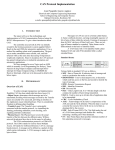
The three transmit message buffers and one double-buffered receive message buffer of MSCAN are
organized as shown in Figure 1-1.
1. Depending on the actual bit timing and the clock jitter of the PLL.
MOTOROLA
Overview
For More Information On This Product,
Go to: www.freescale.com
1-3
Overview
Freescale Semiconductor, Inc.
ARCHIVED BY FREESCALE SEMICONDUCTOR, INC. 2005
CPU bus
MSCAN
RxBG
RxFG
Tx Buffer 1
Tx Buffer 3
ARCHIVED BY FREESCALE SEMICONDUCTOR, INC. 2005
Freescale Semiconductor, Inc...
Tx Buffer 2
RXF
TXEx
TXEx
TXEx
Figure 1-1. MSCAN Message Buffers Organization
1.3.1 Message Transmission
All three transmit buffers have 13-byte data structure.
To transmit a message, the available MSCAN transmit buffer shall be identified, which is indicated by a
set Transmit Buffer Empty (TXEx) flag. If the Tx Buffer is available, the Identifier, control bits and data
contents are then stored in one of the transmit buffers, and the buffer is flagged as ready for transmission
by clearing the associated TXEx flag. The MSCAN then schedules the message for transmission and
signals the successful transmission of the buffer by setting the associated TXEx flag. If not masked, the
send ISR is generated when TXEx is set and is used by the driver to re-load the buffer.
In case more than one buffer is scheduled for transmission when the CAN bus becomes available for
arbitration, the MSCAN uses the local priority setting for the three buffers to determine the transmission
order. The local priority reflects the priority of this particular message relative to the set of messages being
transmitted from this node. The lowest binary priority value is defined to be the highest priority.
1.3.2 Message Receiving
The received messages are stored in a two-stage input FIFO. The two message buffers are alternatively
mapped into a single memory area. While the background buffer (RxBG) is exclusively associated with the
MSCAN, the foreground buffer (RxFG) is addressable by the CPU.
The Receiver Full flag (RXF) signals the status of the foreground receive buffer. When the buffer contains
a correctly-received message with the matching Identifier, this flag is set.
1-4
DSP56800/MSCAN Driver User Manual
For More Information On This Product,
Go to: www.freescale.com
MOTOROLA
Freescale Semiconductor, Inc.MSCAN Driver Overview
ARCHIVED BY FREESCALE SEMICONDUCTOR, INC. 2005
On reception, each message is checked to see if it passes the filter and is written in parallel into RxBG. The
MSCAN copies the content of the RxBG into RxFG (if the RXF flag is not set), sets the RXF flag, and
emits the receive ISR. When the received message is read from the RxFG, the RXF flag is reset to
acknowledge the interrupt and to release the foreground buffer. A new message can be immediately
received into RxBG.
The overrun condition occurs when both the foreground and the background receive message buffers are
filled with correctly-received messages with accepted Identifiers and another message with an accepted
Identifier is correctly received from the bus.
ARCHIVED BY FREESCALE SEMICONDUCTOR, INC. 2005
Freescale Semiconductor, Inc...
1.4 MSCAN Driver Overview
The MSCAN driver software described in this manual is designed specifically for use with the
DSP56803/05 MSCAN modules, and is integrated with the Motorola Embedded SDK package for
DSP568xx.
The MSCAN driver software manages the transmission and reception data through the CAN bus by the
MSCAN modules.
The user application accesses the driver routines via the Motorola Embedded SDK API, which provides
common interface for input/output operations.
From the application point of view, the driver provides “pipe” functionality, where unidirectional virtual
pipe connects two (or more in multicast mode ) virtual devices on different DSP units. Each pipe
corresponds to a particular CAN Identifier and provides data transfer by portions up to 8 bytes.
The run-time driver API is based on a device descriptor approach recommended by POSIX standard. To
set up a virtual device, open and close statements are used. Transmission and reception application datais
provided by read and write API statements. The ioctl API statement initializes the MSCAN module, puts
the MSCAN module into low-power SLEEP mode, wake-ups from SLEEP mode and obtains the status of
MSCAN device and descriptor.
The static configuration API provides CAN time settings and two major driver configurations:
•
•
CAN 2.0A or CAN 2.0B protocol (11-bit or 29-bit CAN ID)
Queued or unqueued version
MOTOROLA
Overview
For More Information On This Product,
Go to: www.freescale.com
1-5
Overview
Freescale Semiconductor, Inc.
ARCHIVED BY FREESCALE SEMICONDUCTOR, INC. 2005
Freescale Semiconductor, Inc...
ARCHIVED BY FREESCALE SEMICONDUCTOR, INC. 2005
1-6
DSP56800/MSCAN Driver User Manual
For More Information On This Product,
Go to: www.freescale.com
MOTOROLA
Freescale Semiconductor, Inc.
ARCHIVED BY FREESCALE SEMICONDUCTOR, INC. 2005
2.1 MSCAN Driver Functionality Overview
ARCHIVED BY FREESCALE SEMICONDUCTOR, INC. 2005
Freescale Semiconductor, Inc...
Chapter 2
MSCAN Driver Description
The DSP56803/05 MSCAN Driver routines are designed to provide the application programmer with a
friendly, high-level communication interface to the MSCAN module, allowing the programmer to develop
effective applications without an understanding of the detailed operation of the MSCAN module. The
application programmer can design the application using MSCAN driver routines, knowing that the driver
routines will take all necessary actions to transmit and receive the messages on the CAN bus.
However, additional possibilities are provided for sophisticated users familiar with CAN, who want to
control the device. The CAN may be controlled by accessing the MSCAN registers; i.e., setting
customized values for MSCAN Time Control Registers, or by configuring acceptance filtering.
The application programmer creates generic message buffers which can be opened either for reading or
writing. While opening the message buffer, its features are specified as input parameters of the open API
statement. These features include options such as CAN Identifier, the message data format,
synchronization mode, and transmission type (time-scheduled or priority-scheduled). Every open read or
write message buffer can later be multiply accessed via a corresponding read or write statement to receive
and transmit messages and by an ioctl statement to receive the status of the buffer. To close
communication via the specified message buffer, a close statement is used.
The developer can use the ioctl API statement to control the MSCAN device modes: put it into low-power
SLEEP mode, wake it up, or get the status of the MSCAN control registers.
When the message buffer is successfully opened for writing, it could be accessed by the write API
statement to transmit a message with the corresponding Identifier. The MSCAN driver places the message
data either directly into one of the three MSCAN transmission buffers, or into the transmission queue,
when the QUEUED transmission mode is statically specified. The message is assigned to a local priority.
The write message buffer opened in the priority-scheduled transmission type is assigned a local priority,
defined to be the seven most significant bits of CAN Identifier. The lower CAN Identifier value, the higher
the priority. The time-scheduled message buffers are assigned the lowest possible priority and are
processed after any priority-scheduled message in the sequence of corresponding write statement
appearance. If the transmission message buffer is operating in the asynchronous mode, the write statement
returns immediately after putting a message either into the MSCAN transmission buffer or into the
transmission queue. In the synchronous mode, the write statement does not return immediately after
putting the message into the MSCAN transmission buffer, but waits until the successful message
transmission is signaled by the send ISR.
MOTOROLA
MSCAN Driver Description
For More Information On This Product,
Go to: www.freescale.com
2-1
Freescale Semiconductor, Inc.
MSCAN Driver Description
ARCHIVED BY FREESCALE SEMICONDUCTOR, INC. 2005
Freescale Semiconductor, Inc...
ARCHIVED BY FREESCALE SEMICONDUCTOR, INC. 2005
To avoid transmission buffer overflow, the synchronous transmission mode is used. Otherwise, check the
status of the corresponding message buffer before writing the next message data. The message data should
be written into the buffer with the CANID_EMPTY status.
When the message buffer is successfully opened for read, it could be accessed by the read API statement to
receive a message with the corresponding Identifier. Any read message buffer can have a data buffer, or a
queue of data buffers, to store the messages received by the MSCAN module which passed the
programmable acceptance filter. Any of these messages are processed by the MSCAN driver receive ISR.
The receive ISR searches all read message buffers for a message with a matching CAN Identifier. If a
match is found, the driver stores the received data in the data buffers queue for matching to the read
message buffer. The application program can check the status of message buffers to find out if there are
received messages waiting in the queue. The CANID_FULL message buffer status identifies that a new
message with the matching Identifier has been received and is waiting in the data buffer or in the data
buffer’s queue. If a message with the matching Identifier has been received when all the assigned message
data buffers are occupied, the earliest message from the queue is lost, (the head of the queue is cyclically
shifted), and the message buffer status becomes CANID_OVERFLOW. The application program can read
the data from the head of a buffer queue when the message buffer status is either CANID_FULL or
CANID_OVERFLOW.
The developer may want to speed up the receive ISR to avoid looking through the message buffers to find
the corresponding CAN Identifier. The application programmer can specify his own customized call back
function, which will substitute the search of the matching read buffer. The call back function can return a
pointer to a user-defined buffer where receive ISR will store the message received from CAN. The
application can take the message data directly from the address returned by call back function. Therefore,
there is no need to assign a data buffer to the read message buffer.
2.2 MSCAN Driver Static Configuration
The MSCAN driver can be statically configured to operate either in CAN2.0A or CAN2.0B addressing
mode. In tCAN2.0A addressing mode, the driver operates with standard 11-bit message Identifiers and
assigns four 16-bit acceptance filters. In CAN2.0B addressing mode, the driver operates with extended
29-bit message Identifiers and assigns two 32-bit acceptance filters.
The driver can be statically configured to operate either in QUEUED or UNQUEUED modes:
•
•
For message transmission, the unqueued mode means that the allocated transmission message
buffer does not store the message data. If it is available, the data is written directly to the MSCAN
transmission buffer. When the queued transmission mode is set, each transmission message buffer
is assigned a data buffer to store the message data and length. All the opened message buffers are
stored in queue, either in prioritized or time-sequenced order.
For message receiving in queued mode, every receiving message buffer is allocated a queue of a
specified size. This queue stores the messages with the matching Identifier received from the bus
before it is read by the application.
The default configuration of the driver is:
—
—
—
—
2-2
CAN2.0A addressing mode
11-bit message Identifiers
four 16-bit acceptance filters
UNQUEUED transmission mode
DSP56800/MSCAN Driver User Manual
For More Information On This Product,
Go to: www.freescale.com
MOTOROLA
Freescale Semiconductor,
Inc.
Application Static Configuration
ARCHIVED BY FREESCALE SEMICONDUCTOR, INC. 2005
To change any of these features, see the corresponding macro definitions specified in file:
<Embedded SDK location>\src\dsp568xxevm\nos\bsp\mscan.h
To set QUEUED mode, specify:
#define CAN_QUEUED_TRANSMISSION
To set CAN2.0B addressing mode with 29-bit message Identifiers and two 32-bit acceptance filters,
specify:
#define CAN20B
The default configuration for MSCAN Driver applications is specified in the file:
ARCHIVED BY FREESCALE SEMICONDUCTOR, INC. 2005
Freescale Semiconductor, Inc...
2.3 Application Static Configuration
<Embedded SDK location>\src\dsp568xxevm\nos\config\config.h
Any of these default features could be redefined to suit the needs of the particular application. This can be
done by setting corresponding macro definitions in the file:
<Application location>\config\appconfig.h
Possible configurable features are described in the next sections.
2.3.1 CAN_MAX_RECEIVE_ID
Set the CAN_MAX_RECEIVE_ID value to specify the maximum possible number of open read buffers.
This constant value is introduced to control memory consumption of the application.
The default value for CAN_MAX_RECEIVE_ID is seven; i.e., seven buffers can be opened for read, and
messages with seven different CAN Identifiers can be received.
2.3.2 CAN_MAX_TRANSMIT_ID
Set the CAN_MAX_TRANSMIT_ID value to specify the maximum possible number of open write
buffers. This constant value is introduced to control memory consumption of the application.
The default value for CAN_MAX_RECEIVE_ID is seven; i.e., seven buffers can be opened for write, and
messages with seven different CAN Identifiers can be transmitted.
2.3.3 CAN_SPEED
Set the CAN_SPEED value to assign bit timing values for MSCAN Time Control Registers. Use one of the
widely used CAN speed values listed in the file <Embedded SDK
location>\src\dsp568xxevm\nos\config\config.h to set the most appropriate CBTR0 and CBTR1 values,
or to specify custom bit timing values for:
— CAN_TIME_SEGMENT1
— CAN_TIME_SEGMENT2
MOTOROLA
MSCAN Driver Description
For More Information On This Product,
Go to: www.freescale.com
2-3
Freescale Semiconductor, Inc.
MSCAN Driver Description
ARCHIVED BY FREESCALE SEMICONDUCTOR, INC. 2005
— CAN_PRESCALER
— CAN_SAMPLING
— CAN_SYNCH_JUMP_WIDTH
Refer to the CAN Specifications and the DSP56F80x User’s Manual for details of MSCAN register’s
description.
2.3.4 CAN_TIME_SEGMENT1
ARCHIVED BY FREESCALE SEMICONDUCTOR, INC. 2005
Freescale Semiconductor, Inc...
Set the CAN_TIME_SEGMENT1 value to directly specify the length of the Time Segment 1 in clock
cycles. Refer to the CAN Specifications for details of the MSCAN time control register’s description.
When the CAN_SPEED value is specified, the CAN_TIME_SEGMENT1 value may not be set and all
timing characteristics will be set automatically.
2.3.5 CAN_TIME_SEGMENT2
Set the CAN_TIME_SEGMENT2 value to directly specify the length of the Time Segment 2 in clock
cycles. Refer to the CAN Specifications for details of the MSCAN time control register’s
description.When the CAN_SPEED value is specified, the CAN_TIME_SEGMENT2 value may not be set
and all timing characteristics will be set automatically.
2.3.6 CAN_PRESCALER
Set CAN_PRESCALER to specify the Baud Rate Prescaler. Refer to CAN Specifications for details of the
MSCAN time control register’s description. When the CAN_SPEED value is specified, the
CAN_PRESCALER value may not be set and all timing characteristics will be set automatically.
2.3.7 CAN_SAMPLING
Set CAN_SAMPLING to specify the number of samples of the serial bus to be taken per bit time. Value
“0” means that one sample is taken per bit; value “1” means that three samples are taken. When the
CAN_SPEED value is specified, the CAN_SAMPLING value may not be set and all timing characteristics
will be set automatically.
2.3.8 CAN_SYNCH_JUMP_WIDTH
Set CAN_SYNCH_JUMP_WIDTH to define the maximum number of clock cycles a bit can be shortened
or lengthened to achieve resynchronization to data transitions on the bus. Refer to the CAN Specifications
for details of the MSCAN time control register’s description. When the CAN_SYNCH_JUMP_WIDTH
value is specified, the CAN_TIME_SEGMENT2 value may not be set and all timing characteristics will be
set automatically.
2-4
DSP56800/MSCAN Driver User Manual
For More Information On This Product,
Go to: www.freescale.com
MOTOROLA
Freescale Semiconductor,
Inc.
Application Static Configuration
ARCHIVED BY FREESCALE SEMICONDUCTOR, INC. 2005
2.3.9 CAN_STOP_IN_WAIT_MODE
The CAN_STOP_IN_WAIT_MODE can be set to either “0” or “1” and is used to indicate whether the
low- power consumption for the MSCAN module is enabled in WAIT mode by disabling all the clocks at
the bus interface. Value “1” means that the MSCAN module ceases to be clocked during WAIT mode,
value “0” means that the MSCAN module is not affected during WAIT mode.
The default value for CAN_STOP_IN_WAIT_MODE is “0”; i.e., MSCAN does not stop in the WAIT
mode.
ARCHIVED BY FREESCALE SEMICONDUCTOR, INC. 2005
Freescale Semiconductor, Inc...
2.3.10 CAN_LOOP_BACK
The CAN_LOOP_BACK can be set to either “0” or “1”. When set to “1”, it configures MSCAN to operate
in the self-test mode. The bit stream output of the transmitter is fed back to the receiver internally. The
MSCAN behaves as it does normally when transmitting and treats its own transmitted message as a
message received from the remote node.
The default value for the CAN_LOOP_BACK is “0”; i.e., loopback self-test mode is disabled, and the
transmitted messages are not received.
2.3.11 CAN_WAKE_UP_MODE
The CAN_WAKE_UP_MODE can be set to either “0” or “1” and is used to indicate whether the
integrated low-pass filter is applied to protect the MSCAN module from a spurious wake-up. See the
DSP56F80x User’s Manual for the MSCAN SLEEP mode description. Value “1” means that MSCAN
wakes up the CPU only in the case of a continuous dominant pulse on the bus, value “0” means that
MSCAN wakes up the CPU after any recessive to dominant edge on the CAN bus.
The default value for CAN_WAKE_UP_MODE is “0”; i.e., MSCAN is not protected from a spurious
wake up.
2.3.12 CAN_CLOCK_SOURCE
The CAN_CLOCK_SOURCE defines the type of the MSCAN clock source. Value “0” means that the
Crystal Oscillator Clock is used; value “1” means that the IP bus clock is used. See the DSP56F80x User’s
Manual for MSCAN clock system description.
The default value for the CAN_CLOCK_SOURCE is “1”.
2.3.13 CAN_CUSTOM_FILTER_CODE
The CAN_CUSTOM_FILTER_CODE can be specified to define a custom acceptance filter code value.
Note that the size of the acceptance code should be in the range of 11-bit for CAN2.0A addressing mode
and in the range of 29-bit for CAN2.0B addressing mode. If specified, this value will be used instead of the
automatically assigned value.
By default, the CAN_CUSTOM_FILTER_CODE value is not set; therefore, all the acceptance filters are
automatically assigned while opening message buffers.
MOTOROLA
MSCAN Driver Description
For More Information On This Product,
Go to: www.freescale.com
2-5
Freescale Semiconductor, Inc.
MSCAN Driver Description
Note:
ARCHIVED BY FREESCALE SEMICONDUCTOR, INC. 2005
Custom acceptance filters make sense when employed with the user-defined call back
function.
2.3.14 CAN_CUSTOM_FILTER_MASK
The CAN_CUSTOM_FILTER_MASK can be specified to define a custom acceptance filter mask value.
Note that the size of the acceptance mask should in the range of 11-bit for the CAN2.0A addressing mode
and in the range of 29-bit for the CAN2.0B addressing mode. If specified, this value will be used instead of
the automatically assigned value.
By default, the CAN_CUSTOM_FILTER_MASK value is not set; therefore, all the acceptance filters are
automatically assigned while opening message buffers.
ARCHIVED BY FREESCALE SEMICONDUCTOR, INC. 2005
Freescale Semiconductor, Inc...
Note:
If specified, acceptance code and acceptance mask must both be defined. The acceptance mask
value without the acceptance code specified makes sense only if all the bits are masked. If only
the acceptance code is specified, the acceptance mask will be treated as ‘0’; i.e., no bits are
masked.
2.3.15 CAN_RECEIVE_ID_QUEUE_SIZE
The CAN_RECEIVE_ID_QUEUE_SIZE specifies the size of the message buffer receiving data queue.
The messages with the matching Identifiers received from the CAN and successfully passed through the
acceptance filter are placed into the message buffer data queue, from which the read statement gets
message data. When the queue is full; i.e., the number of received but not read messages is equal to the
queue size, the new message with the matching Identifier will overwrite the earliest message in the queue.
There is no need to specify the queue size when the custom receive call back function is used.
By default, the CAN_RECEIVE_ID_QUEUE_SIZE is set to “1”; i.e., every message received but not read
is overwritten in the buffer. If the raw call back function exists, CAN_RECEIVE_ID_QUEUE_SIZE will
be ignored.
Notes:
•
•
Specify CAN_QUEUED_TRANSMISSION mode to enable receiving queues support for a queue
size greater than one.
The CAN_RECEIVE_ID_QUEUE_SIZE is rounded up to 2 in power of N; i.e., 1, 2, 4, 8, 16, etc.
2.3.16 CAN_RAW_CALLBACK
The CAN_RAW_CALLBACK specifies the name of the call back function, defined within the application
to customize the receive ISR behavior. The standard receive ISR looks through all the opened read buffers
to find the one with the matching Identifier. To avoid this search, and therefore to speed up the ISR
processing, the custom function can be used to return the pointer to the buffer, where it places the received
data.
The call back function must be declared prior to the CAN_RAW_CALLBACK definition, must get the
message Identifier parameter and return the pointer to a can_sData structure, which is specified in:
<Embedded SDK location>\src\dsp568xxevm\nos\include\can.h
2-6
DSP56800/MSCAN Driver User Manual
For More Information On This Product,
Go to: www.freescale.com
MOTOROLA
Freescale Semiconductor, Inc.
Low-Power Modes
ARCHIVED BY FREESCALE SEMICONDUCTOR, INC. 2005
For example:
can_sData* CallBackFunction(UWord32 canid)
By default, the CAN_RAW_CALL_BACK is treated as not specified; i.e., standard data buffer search is
conducted by receive ISR.
Note:
The CAN_RECEIVE_ID_QUEUE_SIZE shall be set to zero or undefined; any non-zero
CAN_RECEIVE_ID_QUEUE_SIZE value will be ignored.
ARCHIVED BY FREESCALE SEMICONDUCTOR, INC. 2005
Freescale Semiconductor, Inc...
2.4 Low-Power Modes
In applications where low current consumption is important, it may be necessary to shut down all or part of
the micro-controller during periods when no processing is required. There are two levels of reduced power
consumption: wait mode and stop mode. These modes are entered by executing the WAIT and STOP
instructions, respectively. Normal processing is resumed when a reset or an interrupt occurs.
The sleep mode is a low-power mode which applies to the MSCAN module only and is independent of the
MCU mode. In SLEEP mode, the MSCAN is shut down in a controlled manner. Transmission and
reception of CAN messages is halted. However, the CANRX input pin remains active and if a transition is
detected on the CAN bus, the MSCAN module will wake-up and function normally after 11 recessive bits
have been detected. A CAN message which wakes up the MSCAN module is therefore not received or
acknowledged, but the next message is received or acknowledged, unless the MCU was in STOP mode.
The MSCAN is requested to enter SLEEP mode by calling ioctl statement in the mode CAN_SET_SLEEP.
The ioctl statement in the mode CAN_GET_STATUS should be used to verify that the MSCAN has
entered SLEEP mode. The MSCAN is awakened from SLEEP mode either by detecting a transition on the
CAN bus, by write statement, or by calling the ioctl statement in the CAN_SET_WAKEUP mode. If the
MSCAN is awakened by a transition on the CAN bus, this will also wake up the MCU from either the
WAIT or the STOP mode. The MSCAN may use a wake-up filter to limit the minimum transition period,
which will wake up the MSCAN. To apply this filter, set CAN_WAKE_UP_MODE, found in file:
<Application location>\config\appconfig.h
In WAIT mode, the CPU and certain other peripheral modules are not clocked; i.e., no longer function.
Some modules may be programmable to function or not function in WAIT mode. The MSCAN may be
programmed to function or not function in WAIT mode by means of setting the
CAN_STOP_IN_WAIT_MODE in the file:
<Application location>\config\appconfig.h
In both cases, the MSCAN may be put in SLEEP mode prior to entering WAIT mode. If the MSCAN is
put into SLEEP mode prior to entering WAIT mode, then a transition on the CAN bus will also wake up
the MCU from WAIT mode.
In STOP mode, the MCU oscillator is shut down, so no modules are clocked. This is the lowest power
consumption mode. No CAN messages can be received during this time. If the MSCAN is put into SLEEP
mode prior to entering STOP mode, a transition on the CAN bus will also wake up the MCU from STOP
mode.
MOTOROLA
MSCAN Driver Description
For More Information On This Product,
Go to: www.freescale.com
2-7
Freescale Semiconductor, Inc.
MSCAN Driver Description
ARCHIVED BY FREESCALE SEMICONDUCTOR, INC. 2005
If the MSCAN is NOT in SLEEP mode, but the MSCAN clocks are stopped by entering STOP mode, or
WAIT mode with CAN_STOP_IN_WAIT_MODE set, a CAN message transmission could be halted part
way through, violating the CAN protocol. Also, the MSCAN module will not wake up when a transition
occurs on the CAN bus, and the MSCAN module may contain garbage data when its clocks are restarted.
2.5 MSCAN Driver Files
The MSCAN driver files are provided in source code and are installed into DSP568xx Embedded SDK.
After installation the MSCAN driver files are distributed as follows:
This is the source file of the MSCAN driver. Do not edit this file.
ARCHIVED BY FREESCALE SEMICONDUCTOR, INC. 2005
Freescale Semiconductor, Inc...
<Embedded SDK location>\src\dsp568xxevm\nos\bsp\mscan.c
<Embedded SDK location>\src\dsp568xxevm\nos\bsp\mscan.h
This is the header file of the MSCAN driver. Do not edit this file except for the static driver configuration
settings: addressing mode (CAN2.0A vs. CAN2.0B) and transmission mode (queued vs. unqueued). To
change the MSCAN Driver static configuration, set the appropriate #define in mscan.h and rebuild the
bsp.mcp project.
<Embedded SDK location>\src\dsp568xxevm\nos\include\can.h
This is the application header file. It is included into an application source code to provide access to the
MSCAN Driver interface structures, data types, and constants. For a detailed description of the application
data types, see in Section 2.7.
<Embedded SDK location>\src\dsp568xxevm\nos\config\config.c
This is the SDK file, responsible for initialization of such SDK componentsas Input/Output, Memory
Management, Timers Management, etc. See the Embedded SDK Programmer’s Guide for details.
Note:
This file will not be modified by the MSCAN driver installation. Therefore, the MSCAN
driver initialization code must be inserted into this file manually. Find the piece of code bound
by:
#if defined( INCLUDE_CAN )
...
#endif
and substitute it with the piece of code provided in the readme.txt file.
<Embedded SDK location>\src\dsp568xxevm\nos\config\config.h
This is the SDK file, responsible for configuration of SDK components. This file specifies whether the
particular SDK component is built into the system, and sets default values for the application configuration
features for these components. Features specified in the config.h file can be overwritten by definition in the
application’s appconfig.h file, located in:
<Application location>\config\appconfig.h
See the Embedded SDK Programmer’s Guide for details.
2-8
DSP56800/MSCAN Driver User Manual
For More Information On This Product,
Go to: www.freescale.com
MOTOROLA
Freescale Semiconductor, Inc.
Note:
Application Files
ARCHIVED BY FREESCALE SEMICONDUCTOR, INC. 2005
This file will not be modified by the MSCAN driver installation. Therefore, the MSCAN
Driver initial configuration code must be inserted into this file manually. Find the piece of
code bound by:
#ifdef INCLUDE_CAN
...
#endif
and substitute it with the piece of code provided in the readme.txt file.
<Embedded SDK location>\src\dsp568xxevm\nos\application\can\
This folder contains the DSP part of the demo application utilizing the MSCAN Driver API functions. For
a detailed description of the demo, see Appendix A.5 .
This folder contains the PC part of the demo application utilizing the MSCAN Driver API functions. For a
detailed description of the demo, see Appendix A.5 .
ARCHIVED BY FREESCALE SEMICONDUCTOR, INC. 2005
Freescale Semiconductor, Inc...
<Embedded SDK location>\src\x86\win32\applications\can\
2.6 Application Files
The main application source file to utilize the MSCAN Driver API resides in the <Application location>
and includes the following files:
#include
#include
#include
#include
#include
#include
"port.h"
"arch.h"
"io.h"
"periph.h"
"fcntl.h"
"can.h"
The <Application location>\config directory contains files appconfig.c, appconfig.h, and linker.cmd. See
the Embedded SDK Programmer’s Guide for details.
The appconfig.h file provides the mechanism to overwrite the default initial configuration settings,
specified in the file:
<Embedded SDK location>\src\dsp568xxevm\nos\config\config.h
The appconfig.h file for an application utilizing the MSCAN driver should specify that MSCAN support is
enabled:
#define INCLUDE_CAN
Any application configuration features described in Section 2.3 can also be defined in the appconfig.h file
to customize the particular application. For example:
#define CAN_SPEED
100000
#define CAN_MAX_TRANSMIT_ID 2
transmitting buffers*/
MOTOROLA
/* specify CAN speed */
/* overwrite default number of
MSCAN Driver Description
For More Information On This Product,
Go to: www.freescale.com
2-9
Freescale Semiconductor, Inc.
MSCAN Driver Description
ARCHIVED BY FREESCALE SEMICONDUCTOR, INC. 2005
2.7 Application Data Types
The data types to be used by the application programmer in the MSCAN driver API calls are specified in
the file:
<Embedded SDK location>\src\dsp568xx\nos\include\can.h
A detailed description of each follows:
/* structure type for opening a buffer */
typedef struct{
UWord32 canID;
can_eScheduleType scheduleType;
can_eFormat messageFormat;
}can_sOpenParams;
ARCHIVED BY FREESCALE SEMICONDUCTOR, INC. 2005
Freescale Semiconductor, Inc...
2.7.1 can_sOpenParams
A structure variable of can_sOpenParams type specifies the parameters of the new message buffer created
by the open statement. The description of the structure fields types follows:
2.7.2 can_eFormat
/* types of char format */
typedef enum
{
CAN_8BIT = 7,
CAN_16BIT = 8
} can_eFormat;
The can_eFormat enumerator data type specifies possible values for the messageFormat field of the
can_sOpenParams structure. It defines the type of data, which is to be sent or received from the buffer.
When the data elements are 16-bit size, the CAN_16BIT value shall be used; each data element will
occupy two data bytes, and only four data elements are sent in one CAN frame. When the data elements
can fit to 8 bits, the CAN_8BIT format is used; each data element occupies one data byte of the CAN
frame; i.e., eight data elements can be sent in one CAN frame.
2.7.3 can_eScheduleType
/* types of transmission schedule */
typedef enum
{
CAN_TIME_SCHEDULE,
CAN_PRIORITY_SCHEDULE
} can_eScheduleType;
The can_eScheduleType enumerator data type specifies possible values for scheduleType field of the
can_sOpenParams structure. It defines the type of transmission schedule for messages transmitted from
the opened buffer. The messages in CAN_PRIORITY_SCHEDULE are assigned a local priority taken as
seven most significant bits of the message CAN Identifier. The lower the Identifier value, the higher the
priority. Messages are transmitted, then placed into the queue in priority order. In the case of the
2-10
DSP56800/MSCAN Driver User Manual
For More Information On This Product,
Go to: www.freescale.com
MOTOROLA
Freescale Semiconductor, Inc.
Driver Memory Requirements
ARCHIVED BY FREESCALE SEMICONDUCTOR, INC. 2005
CAN_TIME_SCHEDULE schedule type, the messages of the corresponding buffer will be transmitted
and placed into the queue in the order of the corresponding write statement appearance. The local priority
of such messages will be considered to be lower than any priority-scheduled message.
Notes:
•
•
While using the priority-scheduled transmission mode, only the seven most significant bits are
used for priority arbitration; i.e., the messages with CAN Identifiers 0x0001 and 0x002 will have
the same priority.
The messageFormat field is not used for receiving message buffers.
ARCHIVED BY FREESCALE SEMICONDUCTOR, INC. 2005
Freescale Semiconductor, Inc...
2.7.4 can_sData
/* structure type for data exchange */
typedef struct
{
UWord16 length; /* length message */
unsigned char data[8]; /* message data */
} can_sData;
A structure variable of a type can_sData is used to specify a custom buffer for received message data when
call back function is defined. Custom call back function returns a pointer to a structure of can_sData type.
When there is no CAN_RAW_CALLBACK defined, data buffers are allocated internally by the driver.
2.8 Driver Memory Requirements
The following memory requirements are applicable to the MSCAN Driver code. The measured data is
provided on the standard manner for DSP56800 family architecture1 in 16-bit words. In real application,
this data can be less due to deadstrip of unused code.
2.8.1 MSCAN Driver Code
2.8.1.1 Unqueued Transmission Mode, 11-bit Standard Addressing Type:
•
•
•
Code ROM: 1448
Data ROM: 24
RAM: 56
2.8.1.2 Unqueued Transmission Mode, 29-bit Extended Addressing Type:
•
•
•
Code ROM: 1863
Data ROM: 24
RAM: 56
1. For example the array “unsigned char buf[10];” consumes 10 16-bit words or 20 bytes. However “sizeof(buf)” equals 10 for this
architecture.
MOTOROLA
MSCAN Driver Description
For More Information On This Product,
Go to: www.freescale.com
2-11
Freescale Semiconductor, Inc.
MSCAN Driver Description
ARCHIVED BY FREESCALE SEMICONDUCTOR, INC. 2005
2.8.1.3 Queued Transmission Mode, 11-bit Standard Addressing Type:
•
•
•
Code ROM: 1634
Data ROM: 24
RAM: 57
2.8.1.4 Queued Transmission Mode, 29-bit Extended Addressing Type:
•
•
•
Code ROM: 2049
Data ROM: 24
RAM: 57
The minimal reasonable CAN application can consume the following1:
ARCHIVED BY FREESCALE SEMICONDUCTOR, INC. 2005
Freescale Semiconductor, Inc...
2.8.2 MSCAN Driver Simple Application Code
•
•
•
Code ROM: 412
Data ROM: 76
RAM: 121
1. The data is given from testing results.
2-12
DSP56800/MSCAN Driver User Manual
For More Information On This Product,
Go to: www.freescale.com
MOTOROLA
Freescale Semiconductor, Inc.
ARCHIVED BY FREESCALE SEMICONDUCTOR, INC. 2005
3.1 Overview
ARCHIVED BY FREESCALE SEMICONDUCTOR, INC. 2005
Freescale Semiconductor, Inc...
Chapter 3
API Functional Description
This section describes the Application Programming Interface, (API), functions of the driver in detail. The
MSCAN driver API functions are implemented within the Motorola Embedded SDK I/O API, unified for
all SDK components.
3.1.1 Error Codes
The CANerrno external variable is set by the MSCAN if an error occurs. Table 3-1 lists error codes.
Table 3-1. Error Codes
Enumeration
Value
Description
CAN_ERR_LOST
-1
The message is lost
CAN_ERR_SYNCH
-2
MSCAN module is not synchronized to the CAN bus
CAN_ERR_BUSOFF
-3
MSCAN module is in bus-off state
CAN_ERR_BUSY
1
All buffers are occupied
CAN_ERR_PARAMETER
2
Reserved for future use
CAN_ERR_REOPEN
3
MSCAN module is in reset state
CAN_ERR_NO_BUFFERS
4
No more free buffers for opening
CAN_ERR_CALL
5
API function incorrectly called
3.2 open API statement
3.2.1 Prototype
int open (const char * pName, int oFlags, can_sOpenParams* pParams)
MOTOROLA
API Functional Description
For More Information On This Product,
Go to: www.freescale.com
3-1
Freescale Semiconductor, Inc.
API Functional Description
ARCHIVED BY FREESCALE SEMICONDUCTOR, INC. 2005
3.2.2 Arguments Description
The arguments displayed in Table 3-2 are taken by the open statement.
Table 3-2. open Statement Parameters
ARCHIVED BY FREESCALE SEMICONDUCTOR, INC. 2005
Freescale Semiconductor, Inc...
Argument
Value
Description
pName
BSP_DEVICE_NAME_CAN_0
MSCAN device descriptor. Must be chosen from the list
of possible SDK components descriptors, specified in
<Embedded SDK location>\src\dsp568xx\nos\include\bsp.h
oFlags
O_RDONLY
Open for reading
O_WRONLY,
Open for writing in synchronous (blocking) mode
O_WRONLY|O_NONBLOCK
Open for writing in asynchronous (non-blocking) mode
pParams
A pointer to a structure of can_sOpenParams type.
See Section 2.7.1 for details.
3.2.3 Return Values and Error Codes
The open statement returns the open handle to the message buffer. If an error is detected, “-1” is returned.
Possible error codes are:
CAN_ERR_PARAMETER = Incorrect flags are set
CAN_ERR_REOPEN = The buffer with the same CAN Identifier is already opened (CAN Identifier
uniquely specifies a read or write message buffer)
Note:
Each particular CAN Identifier must be emitted by only one source. This is a CAN protocol
limitation. The driver checks the accuracy of CAN Identifier assignment on a single
microcontroller only. The user is responsible for guaranteeing the correct assignment of CAN
Identifiers in the entire network
CAN_ERR_NO_BUFFERS = When the number of already-opened read message buffers is equal to
CAN_MAX_RECEIVE_ID, no more buffers can be opened for reading. When the number of
already-opened write message buffers is equal to CAN_MAX_TRANSMIT_ID, no more buffers can be
opened for writing.
Note:
Before using other API calls, check whether the open statement returns “-1” , or the CANerrno
value.
If the device descriptor is other than BSP_DEVICE_NAME_CAN_0, and the open device
is considered to be other than MSCAN, then “-1” is returned, and no error code is set.
3.2.4 Functionality Description
This function opens a particular CAN Identifier, either for reading (reception) or writing (transmission)
and returns the handle to the opened message buffer. The function assigns appropriate features to the
message buffer, as specified in the input structure of type can_sOpenParams, and assigns local priority to
3-2
DSP56800/MSCAN Driver User Manual
For More Information On This Product,
Go to: www.freescale.com
MOTOROLA
Freescale Semiconductor, Inc.
open API statement
ARCHIVED BY FREESCALE SEMICONDUCTOR, INC. 2005
the messages for transmission. It also allocates data buffers for write buffers, when in queued transmission
mode, and for read buffers in the absence of call back. The status of the newly-opened message buffer is
CANID_EMPTY. Every opened read handle can later be accessed by the read statement, every opened
write handle can be accessed by the write statement. Any open handle can be closed by a close statement
and accessed by ioctl statement.
The read statement cannot be applied with the write open handle and the write statement cannot be applied
with the read open handle.
To distinguish wanted CAN messages from unwanted messages, the driver updates MSCAN filters to
receive wanted messages only.
•
•
ARCHIVED BY FREESCALE SEMICONDUCTOR, INC. 2005
Freescale Semiconductor, Inc...
While opening the message buffer for reading, the driver adjusts MSCAN acceptance filters:
To receive the wanted (truly opened) messages properly
To reduce the number of unwanted (other messages on CAN bus) messages to decrease the number
of redundant driver receive interrupts
Because the number of MSCAN filters are limited, the driver uses the almost optimal algorithm to update
filters for newly-opened CAN Identifiers. Each open statement for reading checks the already-specified
filters and either assigns a new filter, or modifies the most appropriate closed filters, to receive a message
with this CAN Identifier1.
Note:
Every open statement for the read message buffer is entering the soft reset state to assign the
updated acceptance filters values. Therefore, some time should be reserved to get the CAN bus
synchronized. When using the write statement immediately after such opening, check the
return value and CANerrno. The CAN_ERR_SYNCH CANErrno value is possible.
3.2.5 Example
void main(void)
{
int
rx1, tx1;
can_sOpenParams Rx;
can_sOpenParams Tx;
Rx.canID = 1;
Rx.messageFormat = CAN_16BIT;
/* opened buffer for reading */
rx1 = open(BSP_DEVICE_NAME_CAN_0, O_RDONLY, &Rx);
Tx.canID = 0xFF;
Tx.scheduleType = CAN_TIME_SCHEDULE;
Tx.messageFormat = CAN_8BIT;
/* opened buffer for writing */
tx1 = open(BSP_DEVICE_NAME_CAN_0, O_WRONLY|O_NONBLOCK, &Tx );
}
1.More optimal techniques are significantly more complex and can not be implemented dynamically, due to memory
restrictions.
MOTOROLA
API Functional Description
For More Information On This Product,
Go to: www.freescale.com
3-3
Freescale Semiconductor, Inc.
API Functional Description
ARCHIVED BY FREESCALE SEMICONDUCTOR, INC. 2005
3.3 close API statement
3.3.1 Prototype
int close(int handle)
3.3.2 Arguments Description
The arguments shown in Table 3-3 are taken by the close statement.
Argument
ARCHIVED BY FREESCALE SEMICONDUCTOR, INC. 2005
Freescale Semiconductor, Inc...
Table 3-3. close Statement Parameters
Value
Handle
Description
The handle to the last previously opened message
buffer.
3.3.3 Return Values and Error Codes
The close statement returns “0” when the buffer was successfully closed. When attempting to close the
buffer which was not the last opened, either for read or write, the buffer will not close, and close will return
“-1”.
3.3.4 Functionality Description
The close statement closes the last of the previously-opened read or write message buffers and adds it to
the number of free buffers. The close statement returns “0”. The CAN Identifier assigned to the closed
buffer can later be used while opening any other buffer.
3.4 read API statement
3.4.1 Prototype
int read(int Handle, void* pBuffer, int size)
3.4.2 Arguments Description
The arguments shown in Table 3-4 are taken by the read statement.
3-4
DSP56800/MSCAN Driver User Manual
For More Information On This Product,
Go to: www.freescale.com
MOTOROLA
Freescale Semiconductor, Inc.
read API statement
ARCHIVED BY FREESCALE SEMICONDUCTOR, INC. 2005
Table 3-4. Read Statement Parameters
Argument
Values
Description
Handle
The handle to the message buffer previously
opened for reading
pBuffer
Pointer to a custom buffer in which to place the read
data
size
[1 - 8] - for CAN_8BIT format
[1 - 4] - for CAN_16BIT format
The maximum size of data to read into the buffer
ARCHIVED BY FREESCALE SEMICONDUCTOR, INC. 2005
Freescale Semiconductor, Inc...
3.4.3 Return Values and Error Codes
The read statement returns the number of successfully read data elements of the type specified by the
messageFormat field of the can_sOpenParams. When the message format is CAN_8BIT, the read data
size ranges from 1 to 8; when the message format is CAN_16BIT, the read data size ranges from 1 to 4.
If an error occurs, “-1” is returned, and a possible error code is:
CAN_ERR_CALL = The buffer is not open or is open for write
If no message with a matching Identifier has been received since the last reading from the buffer, the read
statement returns “0”; no error code is set.
When the size of the read buffer is less than the received message, the unread data will be lost.
3.4.4 Functionality Description
The read statement is intended to receive a CAN message.
This function reads the data of a specified size from the previously-opened for reading message buffer to a
custom buffer, defined in the application. The CAN message is received from the bus, and passed through
the acceptance filter, then placed into the message buffer with the matching CAN Identifier. The status of
this buffer becomes CANID_FULL. The message data from the full buffer can be read by the read
statement.
Note:
Check the status of the message buffer before reading by using the ioctl statement.
3.4.5 Example
void main(void)
{
int rx1;
can_sOpenParams Rx;
char buf[64];
UWord16 read_status;
int bytes = 0;
MOTOROLA
API Functional Description
For More Information On This Product,
Go to: www.freescale.com
3-5
Freescale Semiconductor, Inc.
API Functional Description
ARCHIVED BY FREESCALE SEMICONDUCTOR, INC. 2005
Rx.canID = 1;
Rx.messageFormat = CAN_8BIT;
/* opened buffer for reading */
rx1 = open(BSP_DEVICE_NAME_CAN_0, O_RDONLY, &Rx);
for {;;}
{
/* check whether the new message is received */
read_status = ioctl(rx1, CANID_GET_STATUS, 0);
if (read_status == CANID_FULL)
/* read message data */
bytes += read( rx1, buf[bytes], 8);
}
ARCHIVED BY FREESCALE SEMICONDUCTOR, INC. 2005
Freescale Semiconductor, Inc...
}
3.5 write API statement
3.5.1 Prototype
int write(int Handle, void* pBuffer, int size);
3.5.2 Arguments Description
The arguments in Table 3-5 are taken by the write statement.
Table 3-5. write Statement Parameters
Argument
Value
Description
Handle
The handle to the message buffer previously
opened for writing
pBuffer
Pointer to a custom buffer from which to take
the written data
size
[1 - 8] - for CAN_8BIT format
[1 - 4] - for CAN_16BIT format
The maximum size of data which can be
written into the message buffer
3.5.3 Return Values and Error Codes
The write statement returns the number of successfully written data elements of the type specified by the
messageFormat field of the can_sOpenParams. When the message format is CAN_8BIT, the size of
written data ranges from 1 to 8; and when the message format is CAN_16BIT, the written data range is
from 1 to 4. Transmitted data is truncated by these limits.
3-6
DSP56800/MSCAN Driver User Manual
For More Information On This Product,
Go to: www.freescale.com
MOTOROLA
Freescale Semiconductor, Inc.
write API statement
ARCHIVED BY FREESCALE SEMICONDUCTOR, INC. 2005
If an error is detected, “-1” is returned; possible error codes:
•
CAN_ERR_CALL
— the buffer is not open
— the buffer is open for read
— the buffer is not empty
CAN_ERR_BUSOFF = MSCAN is in the Bus-Off state.
•
Note:
ARCHIVED BY FREESCALE SEMICONDUCTOR, INC. 2005
Freescale Semiconductor, Inc...
•
•
If MSCAN goes to the Bus-Off state, all transmitting messages will be lost.
CAN_ERR_SYNCH = MSCAN is not synchronized to the bus
CAN_ERR_BUSY
The meaning of this statement depends on the mode:
— Unqueued mode
– All three MSCAN transmission buffers are occupied
— Queued mode
– The local priority overflow occurred for time-scheduled messages;the condition of all three
MSCAN transmission buffers empty must occur to reset the local priority
– The message buffer is FULL; the system cannot write to a full buffer
CAN_ERR_LOST
— Synchronized mode = the time out expired, but the message has not been sent from one of the
MSCAN transmission buffers
•
3.5.4 Functionality Description
The write statement is intended to transmit a CAN message.
This function writes data of specified size into the corresponding data buffer in the queued transmission
mode, or directly into one of the three MSCAN transmission buffers in the unqueued mode. In the queued
transmission mode, the write statement returns immediately after placing the message data to a buffer; in
the unqueued mode, when synchronization is enabled (i.e., the buffer was opened without the
O_NONBLOCK flag), the write statement waits until the successful transmission or until the
corresponding buffer is signaled by the send ISR.
Notes:
•
•
The presence or absence of the O_NONBLOCK flag is ignored in the queued transmission mode.
Use the ioctl statement to check the status of the message buffer before writing. The MSCAN
driver will report an error when trying to write to a full buffer.
3.5.5 Example
void main(void)
{
char txbuf[]="MESSAGE";
int
tx1;
UWord16 write_status;
can_sOpenParams Tx;
Tx.canID = 0xFF;
Tx.scheduleType = CAN_TIME_SCHEDULE;
MOTOROLA
API Functional Description
For More Information On This Product,
Go to: www.freescale.com
3-7
Freescale Semiconductor, Inc.
API Functional Description
ARCHIVED BY FREESCALE SEMICONDUCTOR, INC. 2005
Tx.messageFormat = CAN_8BIT;
/* open message buffer for writing */
tx1 = open(BSP_DEVICE_NAME_CAN_0, O_WRONLY|O_NONBLOCK, &Tx );
wrtite_status = ioctl(tx1, CANID_GET_STATUS, 0);
if (write_status == CANID_EMPTY)
/* write to message buffer */
write( tx1, txbuf, 7 ); /* time scheduled */
}
ARCHIVED BY FREESCALE SEMICONDUCTOR, INC. 2005
Freescale Semiconductor, Inc...
3.6 ioctl API statement
3.6.1 Prototype
UWord16 ioctl(int Handle, UWord16 cmd, void * param, ... );
3.6.2 Arguments Description
The arguments in Table 3-6 are taken by the ioctl statement.
Table 3-6. ioctl Statement Parameters
Argument
Value
Handle
cmd
Description
The handle to the message buffer previously
opened for reading or writing
CAN_RESET
Re-initializes MSCAN and MSCAN driver
CAN_SET_SLEEP,
Puts MSCAN into low-power SLEEP mode
CAN_SET_WAKEUP
Wakes up MSCAN from the low-power SLEEP
mode
CAN_GET_STATUS
Gets the status of the MSCAN control registers
CANID_GET_STATUS
Gets the status of the message buffer
3.6.3 Return Values and Error Codes
If an error is found, the ioctl statement returns “0”.
The error code CAN_ERR_PARAMETER will be set if an unknown cmd argument is detected.
3-8
DSP56800/MSCAN Driver User Manual
For More Information On This Product,
Go to: www.freescale.com
MOTOROLA
Freescale Semiconductor, Inc.
ioctl API statement
ARCHIVED BY FREESCALE SEMICONDUCTOR, INC. 2005
3.6.4 Functionality Description
The ioctl statement is intended to control the MSCAN device. The following behaviors may occur,
depending on the cmd parameter specified.
CAN_RESET
The ioctl statement reinitializes the MSCAN device as specified in the corresponding
appconfig.h settings. The MSCAN control registers values are reset and all CAN
Identifier handlers are cleared.
CAN_SET_SLEEP
CAN_SET_WAKEUP
ARCHIVED BY FREESCALE SEMICONDUCTOR, INC. 2005
Freescale Semiconductor, Inc...
The ioctl statement puts the MSCAN device into low-power SLEEP mode; for details, see Section 2.4.
The ioctl statement wakes up the MSCAN device from low-power SLEEP mode; see
Section 2.4 for details.
CAN_GET_STATUS
The ioctl statement writes and returns the 16-bit MSCAN status value, which should
be treated as a combination of the flags shown in Table 3-7.
Table 3-7. MSCAN Status Flags
Status flag
Value
Description
CAN_SYNCHRONIZED
0x1000
MSCAN device is synchronized to a bus
CAN_SLEEP
0x400
MSCAN is in the internal SLEEP mode
CAN_WAKEUP
0x80
While in SLEEP mode, MSCAN detected activity on the bus and
requested wake up
CAN_RX_WARN
0x40
MSCAN device is in the Receiver Warning state; i.e., the Receiver
Error Counter exceeds 96
CAN_TX_WARN
0x20
MSCAN device is in the Transmitter Warning state; i.e., the
Transmitter Error Counter exceeds 96
CAN_RX_ERR
0x10
MSCAN is in the Receiver Error passive state; i.e., the Receiver
Error Counter exceeds 127
CAN_TX_ERR
0x08
MSCAN is in the Transmitter Error passive state; i.e., the
Transmitter Error Counter exceeds 127
CAN_BUSOFF
0x04
MSCAN is in the Bus-Off state; i.e., the Transmit Error Counter
exceeds 255
CAN_OVERRUN
0x02
MSCAN is in the Data Overrun condition
CAN_RX_FULL
0x01
MSCAN received a new message, but the receive buffer is full
The 16-bit MSCAN status value is combined from the less significant 8-bits of the CANCTL0 and
CANTFLG registers. For details of the different statuses and registers’ descriptions, see the DSP56F80x
User’s Manual.
MOTOROLA
API Functional Description
For More Information On This Product,
Go to: www.freescale.com
3-9
Freescale Semiconductor, Inc.
API Functional Description
ARCHIVED BY FREESCALE SEMICONDUCTOR, INC. 2005
CANID_GET_STATUS
The ioctl statement returns the 16-bit message buffer status value. Table 3-8 shows the
possible message buffer status values.
Table 3-8. Message Buffer Status Values
ARCHIVED BY FREESCALE SEMICONDUCTOR, INC. 2005
Freescale Semiconductor, Inc...
Status flag
Description
CANID_EMPTY
No message is stored in the message buffer:
- do not read from the receiving buffer in this state
- write to the transmitting buffer in this state
CANID_FULL
Message data is stored in the message buffer:
- read from the receiving buffer in this state
- do not write to the transmitting buffer in this state
CANID_OVERFLOW
Due to the queue overflow, the earliest message in the receiving
queue is overwritten; this state is possible for the receiving buffers
only
3.6.5 Example
void main(void)
{
char txbuf[]="MESSAGE";
int
tx1;
UWord16 write_status, can_status;
can_sOpenParams Tx;
Tx.canID = 0xFF;
Tx.scheduleType = CAN_TIME_SCHEDULE;
Tx.messageFormat = CAN_8BIT;
/* open message buffer for writing */
tx1 = open(BSP_DEVICE_NAME_CAN_0, O_WRONLY|O_NONBLOCK, &Tx );
can_status = ioctl(tx1, CAN_GET_STATUS, 0);
if (can_status & CAN_SYNCHRONIZED)
{
wrtite_status = ioctl(tx1, CANID_GET_STATUS, 0);
if (write_status == CANID_EMPTY)
/* write to message buffer */
write( tx1, txbuf, 7); /* time scheduled */
}
}
3-10
DSP56800/MSCAN Driver User Manual
For More Information On This Product,
Go to: www.freescale.com
MOTOROLA
Freescale Semiconductor, Inc.
ARCHIVED BY FREESCALE SEMICONDUCTOR, INC. 2005
4.1 Limited Use License Agreement
ARCHIVED BY FREESCALE SEMICONDUCTOR, INC. 2005
Freescale Semiconductor, Inc...
Chapter 4
License
LIMITED USE LICENSE AGREEMENT
PLEASE READ THIS AGREEMENT CAREFULLY BEFORE USING THIS SOFTWARE. BY USING
OR COPYING THE SOFTWARE, YOU AGREE TO THE TERMS OF THIS AGREEMENT.
The software in either source code form ("Source") or object code form ("Object") (cumulatively
hereinafter "Software") is provided under a license agreement ("Agreement") as described herein. Any use
of the Software including copying, modifying, or installing the Software so that it is usable by or
accessible by a central processing unit constitutes acceptance of the terms of the Agreement by the person
or persons making such use or, if employed, the employer thereof ("Licensee") and if employed, the
person(s) making such use hereby warrants that they have the authority of their employer to enter this
license agreement,. If Licensee does not agree with and accept the terms of this Agreement, Licensee must
return or destroy any media containing the Software or materials related thereto, and destroy all copies of
the Software.
The Software is licensed to Licensee by Motorola Incorporated ("Motorola") for use under the terms of this
Agreement. Motorola retains ownership of the Software. Motorola grants only the rights specifically
granted in this Agreement and grants no other rights. Title to the Software, all copies thereof and all rights
therein, including all rights in any intellectual property including patents, copyrights, and trade secrets
applicable thereto, shall remain vested in Motorola.
For the Source, Motorola grants Licensee a personal, non-exclusive, non-assignable, revocable,
royalty-free right to use, copy, and make derivatives of the Source solely in a development system
environment in order to produce object code solely for operating on a Motorola semiconductor device
having a central processing unit ("Derivative Object").
For the Object and Derivative Object, Motorola grants Licensee a personal, non-exclusive, non-assignable,
revocable, royalty-free right to copy, use, and distribute the Object and the Derivative Object solely for
operating on a Motorola semiconductor device having a central processing unit.
Licensee agrees to: (a) not use, modify, or copy the Software except as expressly provided herein, (b) not
distribute, disclose, transfer, sell, assign, rent, lease, or otherwise make available the Software, any
derivatives thereof, or this license to a third party except as expressly provided herein, (c) not remove
obliterate, or otherwise defeat any copyright, trademark, patent or proprietary notices, related to the
Software (d) not in any form export, re-export, resell, ship or divert or cause to be exported, re-exported,
resold, shipped, or diverted, directly or indirectly, the Software or a direct product thereof to any country
which the United States government or any agency thereof at the time of export or re-export requires an
export license or other government approval without first obtaining such license or approval.
MOTOROLA
License
For More Information On This Product,
Go to: www.freescale.com
4-1
License
Freescale Semiconductor, Inc.
ARCHIVED BY FREESCALE SEMICONDUCTOR, INC. 2005
Freescale Semiconductor, Inc...
ARCHIVED BY FREESCALE SEMICONDUCTOR, INC. 2005
THE SOFTWARE IS PROVIDED ON AN "AS IS" BASIS AND WITHOUT WARRANTY OF ANY
KIND INCLUDING (WITHOUT LIMITATION) ANY WARRANTIES OF MERCHANTABILITY OR
FITNESS FOR A PARTICULAR PURPOSE. IN NO EVENT SHALL MOTOROLA BE LIABLE FOR
ANY LIABILITY OR DAMAGES OF ANY KIND INCLUDING, WITHOUT LIMITATION, DIRECT
OR INDIRECT OR INCIDENTAL OR CONSEQUENTIAL OR PUNITIVE DAMAGES OR LOST
PROFITS OR LOSS OF USE ARISING FROM USE OF THE SOFTWARE OR THE PRODUCT
REGARDLESS OF THE FORM OF ACTION OR THEORY OF LIABILITY (INCLUDING WITHOUT
LIMITATION, ACTION IN CONTRACT, NEGLIGENCE, OR PRODUCT LIABILITY) EVEN IF
MOTOROLA HAS BEEN ADVISED OF THE POSSIBILITY OF SUCH DAMAGE. THIS
DISCLAIMER OF WARRANTY EXTENDS TO LICENSEE OR USERS OF PRODUCTS AND IS IN
LIEU OF ALL WARRANTIES WHETHER EXPRESS, IMPLIED, OR STATUTORY, INCLUDING
IMPLIED WARRANTIES OF MERCHANTABILITY OR FITNESS FOR PARTICULAR PURPOSE.
Motorola does not represent or warrant that the Software is free of infringement of any third party patents,
copyrights, trade secrets, or other intellectual property rights or that Motorola has the right to grant the
licenses contained herein. Motorola does not represent or warrant that the Software is free of defect, or
that it meets any particular requirements or need of the Licensee, or that it conforms to any documentation,
or that it meets any standards.
Motorola shall not be responsible to maintain the Software, provide upgrades to the Software, or provide
any field service of the Software. Motorola reserves the right to make changes to the Software without
further notice to Licensee.
The Software is not designed, intended, or authorized for use as components in systems intended for
surgical implant into the body, or other applications intended to support or sustain life, or for any other
application in which the failure of the Software could create a situation where personal injury or death may
occur. Should Licensee purchase or use the Software for any such unintended or unauthorized application,
Licensee shall indemnify and hold Motorola and its officers, employees, subsidiaries, affiliates, and
distributors harmless against all claims, costs, damages, and expenses, and reasonable attorney fees arising
out of, directly or indirectly, any claim of personal injury or death associated with such unintended or
unauthorized use, even if such claim alleges that Motorola was negligent regarding the design or
manufacture of the Software.
The term of this Agreement is for as long as Licensee uses the Software for its intended purpose and is not
in default of any provisions of this Agreement. Motorola may terminate this Agreement if Licensee is in
default of any of the terms and conditions of this Agreement.
This Agreement shall be governed by and construed in accordance with the laws of the State of Arizona
and can only be modified in a writing signed by both parties. Licensee agrees to jurisdiction and venue in
the State of Arizona.
By using, modifying, installing, compiling, or copying the Software, Licensee acknowledges that this
Agreement has been read and understood and agrees to be bound by its terms and conditions. Licensee
agrees that this Agreement is the complete and exclusive statement of the agreement between Licensee and
Motorola and supersedes any earlier proposal or prior arrangement, whether oral or written, and any other
communications relative to the subject matter of this Agreement.
4-2
DSP56800/MSCAN Driver User Manual
For More Information On This Product,
Go to: www.freescale.com
MOTOROLA
Freescale Semiconductor, Inc.
ARCHIVED BY FREESCALE SEMICONDUCTOR, INC. 2005
Appendix A
Demo Application
ARCHIVED BY FREESCALE SEMICONDUCTOR, INC. 2005
Freescale Semiconductor, Inc...
A.1 CAN Test Application
The test application MSCAN loopback mode checks the operation of the MSCAN device. This test
application is located in the file:
<Embedded SDK location>\src\dsp5680Xevm\nos\bsp\test\mscan
The test application is based on standard SDK test API. If application is executed correctly, the string “Test
Passed” will appear on the console window.
A.2 CAN Bus Installation
Two or more boards can be connected by CAN bus. The simplest CAN bus is two wires terminated by 124
ohm resistors, as shown in Figure A-1. EVM board contains CAN terminator resistor, thus corresponded
jumper may be used to circuit this board resistor.
CAN Hi
124 ohm
124 ohm
CAN Low
CANH CANL
CANH CANL
CANH CANL
EVM1
EVM2
EVM3
Figure A-1. CAN Bus
The CANH and CANL pins of the EVM board should be connected with the corresponding BUS wires;
see Table A-1.
MOTOROLA
Demo Application
For More Information On This Product,
Go to: www.freescale.com
A-1
Freescale Semiconductor, Inc.
ARCHIVED BY FREESCALE SEMICONDUCTOR, INC. 2005
Table A-1. Pin Descriptions
EVM
Connector
Jumper
CAN Hi
CAN Low
DSP56803 alpha
J3
-
Pin #4
Pin #3
DSP56805 alpha
J26
-
Pin #4
Pin #3
DSP56803
J3 and/or J13
JG10
Pin #4
Pin #3
DSP56805
J26 and/or J32
JG17
Pin #4
Pin #3
DSP56807
J24
JG7
Pin #4
Pin #3
Comments
•
ARCHIVED BY FREESCALE SEMICONDUCTOR, INC. 2005
Freescale Semiconductor, Inc...
Notes:
•
The Alpha version of both the DSP56805 and DSP56803 EVM contains a hardware bug. To
correct it, introduce the pull-up resistor between 3V and the MSCAN_TX pin.
The External CLK settings of the Alpha version of both the DSP56805 and DSP56803 EVM do
not work dependably. Using the IP Bus CLK is recommended.
A.3 Demo Overview
The MSCAN Driver demo consists of two parts:
•
•
DSP56800 CAN Driver Application
PC Monitor Application
Both parts of the demo are located in the files:
<Embedded SDK location>\src\dsp5680xevm\nos\applications\can
<Embedded SDK location>\src\x86\win32\applications\can
Follow these steps to launch the demo:
•
•
•
•
Use the CAN bus to connect the EVMs
Connect the EVM and the PC COM port by serial cable
— Any PC serial port can be used to connect the EVM and the PC
Download and run the DSP CAN driver application
Start the PC Monitor demo
A.4 DSP5680x Demo Description
A simple program transmits and receives data via the CAN bus and communicates with the PC via serial
port. The application should be compiled, downloaded to the DSP5680x Evaluation Module and run. The
file config\appconfig.h can be edited by the user to change the CAN speed or other static configuration
parameters.
A-2
DSP56800/MSCAN Driver User Manual
For More Information On This Product,
Go to: www.freescale.com
MOTOROLA
Freescale Semiconductor, Inc.
ARCHIVED BY FREESCALE SEMICONDUCTOR, INC. 2005
A.5 PC Demo Description
The PC demo is a Win32 application developed in Microsoft Visual C++ 6.0. The user runs the can.exe file
to launch the PC CAN demo application. This demo application is delivered in source code form and
implemented on standard Win32 API statements. The user can easily build a demo application because it
requires no complicated libraries.
With this application, the user can oversee CAN status, monitor CAN bus activity and control the states of
leds located on the DSP5680x Evaluation Module.
The first dialog asks the user to choose the appropriate PC COM port to connect with the DSP5680x
Evaluation Module.
ARCHIVED BY FREESCALE SEMICONDUCTOR, INC. 2005
Freescale Semiconductor, Inc...
Once the serial port is selected, the main application window is displayed; see Figure A-2.
Figure A-2. Demo Application Main Dialog Window.
The CAN status panel on the left side of the window shows the current CAN state; the left side lamps
correspond to particular bits of CAN status word.
In the upper right corner, the Statistics and Bus utilization panel shows CAN activity statistics, including
the number of bytes transmitted and received and the total and average speed in bytes per second.
In the LED state panel are three lamps which show the state of LEDs located on the DSP5680x Evaluation
Module. The LED state can be toggled by clicking the button to right to the lamp. A new LED state will be
distributed for all DSP5680x Evaluation Modules connected by CAN bus while running the demo
application.
MOTOROLA
Demo Application
For More Information On This Product,
Go to: www.freescale.com
A-3
Freescale Semiconductor, Inc.
ARCHIVED BY FREESCALE SEMICONDUCTOR, INC. 2005
Freescale Semiconductor, Inc...
ARCHIVED BY FREESCALE SEMICONDUCTOR, INC. 2005
A-4
DSP56800/MSCAN Driver User Manual
For More Information On This Product,
Go to: www.freescale.com
MOTOROLA
Freescale Semiconductor, Inc.
ARCHIVED BY FREESCALE SEMICONDUCTOR, INC. 2005
Appendix B
DSP56800/MSCAN Hardware Notes
ARCHIVED BY FREESCALE SEMICONDUCTOR, INC. 2005
Freescale Semiconductor, Inc...
B.1 Allowed Time Segments Settings
The Information Processing Time CAN Specifications of DSP56800/MSCAN should be greater than or
equal to three Time Quantas when the prescaler value is one. If the user does not apply pre-defined driver
CAN speeds, correct bit time settings are the user’s responsibility. The parameters shown in Table B-1
affect the CAN speed assignment.
Table B-1. DSP56800/MSCAN Related Parameters to Assign CAN Speed Manually
Hardware Name
MSCAN Driver Name
Used Alias
Notes
CAN_CLOCK_SOURCE
CLK
IP BUS or External CLK
Prescaler Value
CAN_PRESCALER
PV
Time Segment 1
CAN_TIME_SEGMENT1
TS1
PROP _SEG and PHASE_SEG1 of
CAN Specifications
Time Segment 2
CAN_TIME_SEGMENT2
TS2
PHASE_SEG1 of
CAN Specifications
Synchronization
Jump Width
CAN_SYNCH_JUMP_WIDTH
SJW
EXTAL_CLK
Table B-2 gives an overview of the Allowed Time segment settings for parameter values related to CAN
Speed.
MOTOROLA
DSP56800/MSCAN Hardware Notes
For More Information On This Product,
Go to: www.freescale.com
B-1
Freescale Semiconductor, Inc.
ARCHIVED BY FREESCALE SEMICONDUCTOR, INC. 2005
ARCHIVED BY FREESCALE SEMICONDUCTOR, INC. 2005
Freescale Semiconductor, Inc...
Table B-2. Allowed DSP56800 CAN Speed Related Parameters
B-2
CLK
PV
TS1
TS2
SJW
= 0 (Ext)
>1
5 <= TS1 <= 10
=2
1 <= SJW <= 2
= 0 (Ext)
>1
4 <= TS1 <= 11
=3
1 <= SJW <= 3
= 0 (Ext)
>1
5 <= TS1<= 12
=4
1 <= SJW <= 4
= 0 (Ext)
>1
6 <= TS1 <= 13
=5
1 <= SJW <= 4
= 0 (Ext)
>1
7 <= TS1 <= 14
=6
1 <= SJW <= 4
= 0 (Ext)
>1
8 <= TS1 <= 15
=7
1 <= SJW <= 4
= 0 (Ext)
>1
9 <= TS1 <= 16
=8
1 <= SJW <= 4
= 1 (IP BUS)
=1
4 <= TS1 <= 11
=3
1 <= SJW <= 3
= 1 (IP BUS)
>1
5 <= TS1 <= 10
=2
1 <= SJW <= 2
= 1 (IP BUS)
Any
4 <= TS1 <= 11
=3
1 <= SJW <= 3
= 1 (IP BUS)
Any
5 <= TS1 <= 12
=4
1 <= SJW <= 4
= 1 (IP BUS)
Any
6 <= TS1 <= 13
=5
1 <= SJW <= 4
= 1 (IP BUS)
Any
7 <= TS1 <= 14
=6
1 <= SJW <= 4
= 1 (IP BUS)
Any
8 <= TS1 <= 15
=7
1 <= SJW <= 4
= 1 (IP BUS)
Any
9 <= TS1 <= 16
=8
1 <= SJW <= 4
DSP56800/MSCAN Driver User Manual
For More Information On This Product,
Go to: www.freescale.com
MOTOROLA
Freescale Semiconductor, Inc.
ARCHIVED BY FREESCALE SEMICONDUCTOR, INC. 2005
Index
A
E
acceptance filters 2-5, 3-3
API xi, 1-1
Application Program Interface
API xi, 1-1
arbitration field 1-2
error codes 3-1
Error Frame 1-2
I
ARCHIVED BY FREESCALE SEMICONDUCTOR, INC. 2005
Freescale Semiconductor, Inc...
C
call back function 2-2, 2-6
CAN xi, 1-1
CAN ID xi
CAN Identifier
CAN ID xi
CAN_16BIT 2-10
CAN_8BIT 2-10
CAN_ERR_BUSOFF 3-7
CAN_ERR_BUSY 3-7
CAN_ERR_CALL 3-5, 3-7
CAN_ERR_LOST 3-7
CAN_ERR_NO_BUFFERS 3-2
CAN_ERR_PARAMETER 3-2, 3-8
CAN_ERR_REOPEN 3-2
CAN_ERR_SYNCH 3-7
CAN_GET_STATUS 3-9
CAN_PRIORITY_SCHEDULE 2-10
CAN_RESET 3-9
CAN_SET_SLEEP 2-7, 3-9
CAN_SET_WAKEUP 2-7, 3-9
CAN_STOP_IN_WAIT_MODE 2-7
CAN_TIME_SCHEDULE 2-11
CANID_EMPTY 3-10
CANID_FULL 3-10
CANID_GET_STATUS 3-10
CANID_OVERFLOW 3-10
close 2-1, 3-4
Controller Area Network
CAN xi, 1-1
D
Data Frame 1-2
Data Length Code 1-2
DLC xi
Digital Signal Processor
DSP xi
DLC xi
DSP xi
MOTOROLA
IDE xi
Identifier Extension
IDE xi
Interrupt Service Routine
ISR xi
ioctl 2-1, 3-8
ISR xi
M
MCU xi
memory requirements 2-11
MicroController Unit
MCU xi
Motorola Scalable Controller Area Network
MSCAN xi, 1-1
MSCAN xi, 1-1
MSCAN background receive buffer 1-4
MSCAN foreground receive buffer 1-4
MSCAN status values 3-9
MSCAN transmit buffers 1-4
O
open 2-1, 3-2
overrun condition 1-5
P
priority-scheduled transmission 2-1, 2-10
Q
queued mode 2-2
R
RAM xi
Random Access Memory
RAM xi
read 2-2, 3-4
Read Only Memory
ROM xi
Remote Frame 1-2
Remote Transmission Request
RTR xi
Index
For More Information On This Product,
Go to: www.freescale.com
iii
Freescale Semiconductor, Inc.
ARCHIVED BY FREESCALE SEMICONDUCTOR, INC. 2005
Remote Transmission Request Frame 1-2
ROM xi
RTR xi
SDK xi, 1-1
SLEEP mode 2-7
sleep mode 2-7
Software Development Kit
SDK xi, 1-1
SRR xi
stop mode 2-7
Substitute Remote Request
SRR xi
synchronous transmission 2-2
ARCHIVED BY FREESCALE SEMICONDUCTOR, INC. 2005
Freescale Semiconductor, Inc...
S
T
time-scheduled transmission 2-1
U
unqueued mode 2-2
W
wait mode 2-7
write 2-1, 3-6
iv
DSP56800/MSCAN Driver User Manual
For More Information On This Product,
Go to: www.freescale.com
MOTOROLA
Freescale Semiconductor, Inc.
ARCHIVED BY FREESCALE SEMICONDUCTOR, INC. 2005
Freescale Semiconductor, Inc...
ARCHIVED BY FREESCALE SEMICONDUCTOR, INC. 2005
MOTOROLA
Index
For More Information On This Product,
Go to: www.freescale.com
v
Freescale Semiconductor, Inc.
ARCHIVED BY FREESCALE SEMICONDUCTOR, INC. 2005
Freescale Semiconductor, Inc...
ARCHIVED BY FREESCALE SEMICONDUCTOR, INC. 2005
vi
DSP56800/MSCAN Driver User Manual
For More Information On This Product,
Go to: www.freescale.com
MOTOROLA
Freescale Semiconductor, Inc.
ARCHIVED BY FREESCALE SEMICONDUCTOR, INC. 2005
Freescale Semiconductor, Inc...
ARCHIVED BY FREESCALE SEMICONDUCTOR, INC. 2005
For More Information On This Product,
Go to: www.freescale.com
Freescale Semiconductor, Inc.
ARCHIVED BY FREESCALE SEMICONDUCTOR, INC. 2005
Freescale Semiconductor, Inc...
ARCHIVED BY FREESCALE SEMICONDUCTOR, INC. 2005
Motorola reserves the right to make changes without further notice to any products herein. Motorola makes no warranty, representation or guarantee regarding the
suitability of its products for any particular purpose, nor does Motorola assume any liability arising out of the application or use of any product or circuit, and
specifically disclaims any and all liability, including without limitation consequential or incidental damages. “Typical” parameters which may be provided in Motorola
data sheets and/or specifications can and do vary in different applications and actual performance may vary over time. All operating parameters, including
“Typicals” must be validated for each customer application by customer’s technical experts. Motorola does not convey any license under its patent rights nor the
rights of others. Motorola products are not designed, intended, or authorized for use as components in systems intended for surgical implant into the body, or other
applications intended to support or sustain life, or for any other application in which the failure of the Motorola product could create a situation where personal injury
or death may occur. Should Buyer purchase or use Motorola products for any such unintended or unauthorized application, Buyer shall indemnify and hold Motorola
and its officers, employees, subsidiaries, affiliates, and distributors harmless against all claims, costs, damages, and expenses, and reasonable attorney fees
arising out of, directly or indirectly, any claim of personal injury or death associated with such unintended or unauthorized use, even if such claim alleges that
Motorola was negligent regarding the design or manufacture of the part. Motorola and the Stylized M Logo are registered trademarks of Motorola, Inc. Motorola,
Inc. is an Equal Opportunity/Affirmative Action Employer.
MOTOROLA and the Stylized M Logo are registered in the US Patent & Trademark Office. All other product or service names are the property of their
respective owners. © Motorola, Inc. 2002.
How to reach us:
USA/EUROPE/Locations Not Listed: Motorola Literature Distribution; P.O. Box 5405, Denver, Colorado 80217. 1–303–675–2140 or 1–800–441–2447
JAPAN: Motorola Japan Ltd.; SPS, Technical Information Center, 3–20–1, Minami–Azabu. Minato–ku, Tokyo 106–8573 Japan. 81–3–3440–3569
ASIA/PACIFIC: Motorola Semiconductors H.K. Ltd.; Silicon Harbour Centre, 2 Dai King Street, Tai Po Industrial Estate, Tai Po, N.T., Hong Kong. 852–26668334
Technical Information Center: 1–800–521–6274
HOME PAGE: http://www.motorola.com/semiconductors/
For More Information On This Product,
Go to: www.freescale.com
SDK116/D