1
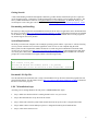
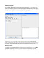
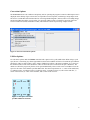
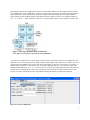
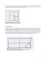
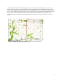
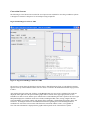
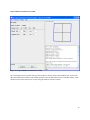
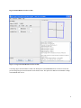
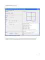
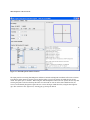
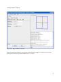
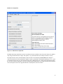
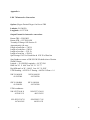
Leo Version 7.0 User Manual
Glennon F. Gagnon
Kansas Geological Survey
December 2008
Historical Overview:
LEO 7.0 is a computer program that converts Kansas Public Land Survey System (PLSS) legal land descriptions to
geographic coordinates and vice versa. The program is designed to run as a stand-alone application allowing users to
perform conversions without access to a networked environment. A web-based version of the tool will be available
also, under the name LEOWEB 7.0. Links are available at http://www.kgs.ku.edu/software/LEO.
The application is not a surveying tool and only provides an approximate conversion. Written in Java, the program is
the latest of several applications developed at the Kansas Geological Survey designed to perform such calculations.
The first program was written in 1964 by Donald Good (1964). His program used 126 land locations and an
arbitrary map-coordinate system to test the possibility of using a computer to convert section, township, and range
notation to Cartesian coordinates. Good’s program was written in FORTRAN II for an IBM 1620 computer.
Subsequent programs, such as KANS, developed by Charles O. Morgan and Jesse M. McNellis (1969) offered
significant improvements, including the ability to calculate latitude and longitude values. KANS was written in
FORTRAN IV and tested on an IBM 7040 at the University of Kansas Computing Center. The program utilized 948
latitude and longitude control points and 962 township and range correction parameters.
These early programs ran in a mainframe environment, making access to the general public impractical. With the
advent of the PC, however, Survey employee Charles G. Ross (1989) saw an opportunity to write such a program.
Ross named the program LEO, a play on words “LEGAL to GEO.” In 1994 LEO II was released as a second generation version of the program. Subsequent development work was performed by David R. Collins with the
release of LEO 3.4, LEO 3.6, and the final DOS-based version, LEO 3.9, released in 1999. Until LEO 7.0, all
versions were written in FORTRAN 77 for IBM-compatible personal computers. Designed as a DOS program, it
remains a popular tool for researchers, government agencies, industry, and the public.
With today’s Windows-style operating systems, powerful low-cost computers, software, and the Internet, almost
anyone can gain access to Geographic Information System (GIS) mapping tools. This, coupled with the increased
use of NAD83 lat/lon coordinates and Global Positioning System (GPS) devices, has created a demand for a new
version of LEO. In 2007 work began on a GUI version of the program.
LEO 7.0 takes advantage of today’s powerful PC’s. It is a stand-alone application written in Java that incorporates
over 60 program files and utilizes nearly 11MB of disk storage space. A binary data file containing data points for
more than 80,000 PLSS sections accounts for most of the storage requirements. The Java language was chosen for
portability. By design, the same conversion algorithms that are used in the stand-alone routines will also be used in
the Survey’s web-based version, running on a Sun V440 computer with the Solaris 8 operating system.
In theory, LEO 7.0 should run on any operating system that supports the Java platform. However, computing
resources must be considered. The application was developed on a Dell Dimension 4700 computer having a Pentium
4 processor, 1GB of RAM, and running the Windows XP operating system. The code was compiled using the SUN
Microsystems Java Development Kit (JDK6) and must be executed with the Java Runtime Environment (JRE)
version 1.6.0_06 or newer. The JRE requirement exists because certain Java language constructs are not available in
earlier JRE versions. LEO 7.0 has been tested on Pentium machines running Windows 2000, XP, and Cent OS
operating systems. A beta version of LEO 7.0 was made available to the public in the fall of 2008.
This document serves as the User Manual for the LEO 7.0 application and is intended to assist users with various
features of the program.
1
Getting Started:
A basic understanding of latitude and longitude coordinates, geodetic datums, and the PLSS system is required to
use the program properly. Fortunately a wealth of information on these subjects can be found on the internet. The
Survey’s Public Information Circular 20, “The public land survey system in Kansas”, by Daniel R. Suchy, is an
excellent place to start. This paper can be found online at http://www.kgs.ku.edu/Publications/pic20/pic20_1.html.
Downloading and Installing:
The most up-to-date program files and installation instructions for the LEO 7.0 application can be downloaded from
the Survey’s web site at http://www.kgs.ku.edu/software/LEO/LEO_07.html. Although the instructions are intended
for the Windows XP operating system, a user with sufficient computer skills should be able to run the program on
any OS that supports the JAVA platform.
System Requirements:
The ability to run the same computer code on multiple operating systems and free “open source” software licensing
were key factors in the decision to write the application in JAVA. LEO 7.0 was compiled using the SUN
Microsystems Java Development Kit (JDK6) and must be executed using the Java Runtime Environment (JRE)
version 1.6.0_06 or newer. Go to http://java.sun.com/javase/downloads/index.jsp to download the latest JRE. If the
user already has a JRE installed, the version number can be identified by entering java -version at the command
prompt. The version information will appear similar to the following message:
C:\java -version
java version "1.6.0_06"
Java(TM) SE Runtime Environment (build 1.6.0_06-b02)
Java HotSpot(TM) Client VM (build 10.0-b22, mixed mode, sharing)
Download LEO Zip File:
Once the JRE has been installed the user is ready to download the LEO zip file that contains the program files and
support documentation. Visit the LEO web site at http://www.kgs.ku.edu/software/LEO/LEO_07.html to download
the latest version of the program.
LEO 7.0 Installation Steps:
Assuming you are running Windows XP and you have ADMINISTRATIVE rights:
•
Step 1.) Make sure that the machine is running the JRE version 1.6.0_06 or newer.
•
Step 2.) Download the LEO 07 zip file from the website.
•
Step 3.) Extract the entire KGS_LEO7 folder and all files from the zip file to the C:\Program Files folder.
•
Step 4.) Make a shortcut on the desktop to point to C:\Program Files\KGS_LEO7\runLEO07.bat.
•
Step 5.) Click on the shortcut to run.
2
Running the Program:
After downloading and installing the program files and creating the desktop shortcut, the user is ready to run the
program. Upon starting LEO 7.0 the user is presented with the display panel depicted in figure 1. At this point you
could convert a latitude/longitude pair to PLSS values by entering coordinates into the text fields and pressing the
Process button (The Reset button clears all entries). Seven input panels are designed for a specific conversion. This
document considers each panel, but first we should highlight some key program features.
Figure 1. Default display panel for LEO 7.0
The display panel can be divided into three key areas. At the top is a menu bar that offers File, Conversion,
Utilities, and Help selections. The display area below the menu bar is partitioned into a left and right side. The left
side is used to set the appropriate geodetic datum and footage-corner parameters and to enter the coordinate values
for conversion. The right side displays the results of the conversion calculations in text and graphic form.
Menu Bar Options:
Four items are on the main menu bar. Each offers sub-menu selections that control the program or provides Help
documentation. The File option allows the user to navigate to the batch processing screen and to “Exit” the
application. Selecting Conversion allows the user to choose from one of seven conversion methods. The Utilities
menu offers tools for specifying the “Quarter call” subdivision levels and setting the PLSS “spot” location.
3
Conversion Options:
The Conversion menu is the workhorse and primary tool for operating the program. It controls which input screen is
displayed on the desktop. Figure 2 shows the seven possible conversion options, each having a unique input screen.
The choices include three data format modes for converting latitude/longitude (lat/lon) values to Township, Range,
and Section (TRS) description, two selections for converting TRS to lat/lon, a method for converting Universal
Transverse Mercator (UTM) coordinates to TRS, and a batch file routine for processing multiple records.
Figure 2. The Conversion menu options
Utilities Options:
Two sub-menu options under the Utilities menu deal with “quarter call” (q-call) subdivisions. When using a q-call
spot, the user is associating (by closest approximation) the actual coordinate location to a fixed PLSS spot within the
subdivision. There are nine possible “spots” within a subdivision. In figure 3 the actual coordinate “X” is closest to
the northwest (NW) corner of the subdivision. LEO 7.0 allows the user to control how the spot is identified. The
default is to allow the program to pick the closest spot mathematically. However this can be overridden to force the
spot to be the center of the smallest specified subdivision. The nine fixed positions are: 1) center of the subdivision,
2) northeast corner, 3) southeast corner, 4) southwest corner, 5) northwest corner, 6) center of the north line, 7)
center of the east line, 8) center of the south line, and 9) center of the west line.
Figure 3. The spot is one of nine
possible subdisivion locations.
4
Specifying the “quarter call” subdivision level is the second control available to the user. Figure 4 shows location
“X” spotted to three levels of subdivision. In LEO 7.0 “quarter calls” are reported “spot first” then from smallest to
largest subdivision. In this example the q-call location could be identified as being the center of the southwest
quarter (smallest) of the southeast quarter of the southwest quarter (largest) of Section 7, Township 9S, Range 5E
(sec. 7, T. 9S., R.5E.). The description is referred to as a “quarter-quarter-quarter call” or simply the “quarter call.”
Figure 4. This image shows three levels of subdivision.
Note: LEO 7.0 can report on up to four levels of subdivision.
The “Set level of subdivision 0-4” option (figure 5) allows the user to specify up to four levels of subdivision. The
default level is level 4 (the equivalent of a “quarter-quarter-quarter-quarter call”). In theory level 4 allows the user to
associate a lat/lon coordinate to the closest “nine point” spot within a 2.5-acre area of the section. For example: A
NAD83 lat/lon coordinate of 38.41039961 and -99.720785 would approximate to a spot near the center of the
NW NE SW SE subdivision of sec. 11, T. 19S., R. 22W. The “Center” spot is approximately 40 feet away from the
actual location. Converting lat/lon values to spot and quarter calls only produces an approximation of the actual
location. Accuracy could be improved by using TRS and footage descriptions if requirements permitted.
Figure 5. Set level of subdivision
5
Valid Kansas Coordinates:
LEO 7.0 is designed to report on locations that fall within the borders of Kansas. To aid the user, generalized data
validation routines have been added that create a warning message when values fall outside a specified range. A list
of valid minimum and maximum values for the LEO 7.0 system are summarized in Table 1.
Table 1
Conversion Option
Parameter
Minimum
Value
Maximum
Value
Decimal Degree Lat/Lon to TRS
Decimal Degree Lat/Lon to TRS
Latitude
Longitude
37.000000
-94.590000
40.000000
-102.05000
Degree Minute Second Lat/Lon to TRS
Degree Minute Second Lat/Lon to TRS
Degree Minute Second Lat/Lon to TRS
Degree Minute Second Lat/Lon to TRS
Degree Minute Second Lat/Lon to TRS
Degree Minute Second Lat/Lon to TRS
Latitude Degrees
Latitude Minutes
Latitude Seconds
Longitude Degrees
Longitude Minutes
Longitude Seconds
36
0
0.00
-94
0
0.00
40
59
59.99
-102
59
59.99
Degree Decimal Minutes Lat/Lon to TRS
Degree Decimal Minutes Lat/Lon to TRS
Degree Decimal Minutes Lat/Lon to TRS
Degree Decimal Minutes Lat/Lon to TRS
Latitude Degrees
Latitude Minutes
Longitude Degrees
Longitude Minutes
36
0.0000
-94
0.0000
40
59.9999
-102
59.9999
TRS Conversions to Lat/Lon
TRS Conversions to Lat/Lon
TRS Conversions to Lat/Lon
TRS Conversions to Lat/Lon
TRS and Offset Footage to Lat/Lon
TRS and Offset Footage to Lat/Lon
Township
Range East
Range West
Section
N-S Footage
E-W Footage
1
1
1
1
0
0
35
25
43
36
5280
5280
UTM Coordinates to Lat/Lon
UTM Coordinates to Lat/Lon
UTM Coordinates to Lat/Lon
Northing
Easting
Zone
Not Validated
Not Validated
13
Not Validated
Not Validated
15
Geodetic Datum:
When working with latitude and longitude coordinates, the North American Datum (NAD) serves as the horizontal
geodetic control. This program allows the user to select either the NAD27 or NAD83 datum. It is essential to record
and specify the correct geodetic datum when capturing and converting lat/lon data. Guessing or specifying the
wrong datum results in calculation errors on the order of 10's of feet.
Footage Corner:
Footages refer to the offset distance from the location spot to the boundary lines of the section. A footage corner is
used to identify which boundary lines are used in calculating the footage offset. If the southeast corner is specified
(default), then the program calculates the offset distance from the south and east lines. Likewise the northwest
6
corner would specify the offset with respect to the north and west boundary lines. Figure 6 depicts a location spotted
1750 feet north of the south line and 2000 feet west of the east line. The LEO 7.0 program uses radio button controls
to allow the user to change the reference corner for offset footages.
Figure 6. Spot footage 1750' north of south line
& 2000' west of east line sec. 22, T. 28 S., R. 1 E.
Irregular Sections:
A section is an area 1/36th of a township bounded by 1 square mile and covering 640 acres. Many sections in Kansas
are smaller or larger than the prescribed nominal section. In fact very few sections are true square miles and less
than 7 percent of Kansas sections actually cover an area equaling 640 acres. Figure 7 shows sec. 6, T. 35 S., R 8 E.,
encompassing 1616 acres. This irregular section is extremely large having east and west boundary lines of 5,284 and
5,285 feet, respectively, and north and south boundary lines of 13,316 and 13,327 feet in length. Fractional sections
are frequently found along the borders and in areas with natural obstacles such as rivers. Users should be aware of
irregular sections and problems associated with converting lat/lon values to legal land descriptions.
Figure 7. Irregular sec. 6, T. 35 S., R. 8 E. covers over 2 square miles
of land. Note: Compare the footage spot to figure 6.
7
Unfortunately LEO 7.0 does not handle irregular sections very well. The southern boundary of sec. 36, T. 26 S.,
R. 20 E. (depicted in figure 8) is a good example of a section boundary that is not a straight line. In this example,
land below the dashed line is still inside the section but not considered in the conversion calculation. This is because
LEO 7.0 only considers the corner points of the section. The program also has problems when subdividing irregular
sections. LEO 7.0 uses an equal subdivision method to divide sections. Plans call for improving accuracy by
enhancing the subdivision algorithm and adding additional control points to outline the boundaries of fractional
sections.
Figure 8. Irregular sec. 36, T. 26 S., R. 20 E. Note: the area below the dashed
line is not considered in the LEO 7.0 conversion.
8
Conversion Screens:
The following is a brief discussion on each of the seven input screens available for converting coordinates. Options
1 through 6 are interactive and option 7 is for batch processing an input file.
Degree Decimal Degree Lat/Lon to TRS:
Figure 9. Degree Decimal Degree Lat/Lon to TRS
The option to convert degree decimal degree lat/lon values to TRS information (figure 9) is the default screen that
appears on start up. Data-validation routines force the values to conform to the minimum/maximum range specified
in table 1.
After entering the input values and “clicking” on the Process button, the conversion is calculated. The results are
displayed on the right side of the panel in both a graphic and text format. In the upper right panel the section
boundaries are drawn to scale, and the spot is marked with a red dot indicating the relative position. The lower righthand panel displays the calculation results in text format, including the TRS values, acreage, length of the four
section boundaries, spot footage, quarter calls, datum, lat/lon coordinates, UTM northing and easting values, and
UTM zone. Scrolling the text box reveals additional information regarding the section including the lat/lon
coordinates for each of the section corners and UTM values associated with the corners (see Appendix A).
Note: The same information is displayed in the graphic and text panels for all of the interactive options.
9
Degree Minute Second Lat/Lon to TRS:
Figure 10. Degree Minute Second Lat/Lon to TRS
The second option converts lat/lon values specified in degrees, minutes, and seconds to TRS. Figure 10 shows the
data input fields and an example of the calculated results. Notice the datum has been set to calculate NAD27 values,
and the reference corner has been set to report using the southwest reference location.
10
Degree Decimal Minutes Lat/Lon to TRS:
Figure 11. Degree Decimal Minutes Lat/Lon to TRS
Converting degree decimal minutes to TRS is the third option on the Conversion menu. For this screen the user
provides integer degrees and real numbers for the minute values. This option was added to accommodate readings
from handheld GPS devices.
11
TRS and Offset Footage to Lat/Lon:
Figure 12. TRS and Offset Footage to Lat/Lon
Option 4 is selected when the user wants to convert TRS and footage information to latitude and longitude
coordinates. The results are returned using the datum and reference corner specified in the dialog screen.
12
TRS and Quarter Calls to Lat/Lon:
Figure 13. TRS and Quarter Calls to Lat/Lon
The input panel for converting TRS and quarter call data to latitude and longitude coordinates offers more selection
tools than any other interactive option. The user has the ability to specify the quarter call subdivision level and
which “nine point spot” to calculate. When using the “TRS and Quarter Calls to Lat/Lon” option, the user may find
selecting the quarter calls from the drop-down lists a bit awkward. In order to enforce data validation rules, the
screen was intentionally designed to require the user to enter the largest subdivision first, using the most right list
(Q1). The user then works “right to left,” entering Q2, Q3, and Q4 as desired.
13
UTM Coordinates to Lat/Lon:
Figure 14. UTM Coordinates to Lat/Lon
When converting UTM coordinates, specifying the geodetic datum and UTM zone is important. Zone 14 is the
default option, but the state of Kansas includes zones 13, 14, and 15.
14
Batch Process Input File:
Figure 15. Batch Process Input File
The Batch Processing option allows the user to perform the same coordinate conversions as the interactive modules,
only using an ASCII text file for input. This option is very useful when the user has many locations to convert.
The input file name can be entered manually in the text field or selected using the Select File button. Output is
written to an ASCII text file. By default the output file name is generated by automatically attaching an ‘LC_’ prefix
to the input file name. However, the output file name can be changed by the user. When using the batch file option,
the user must select the appropriate conversion method using the radio buttons. The input file format must match the
conversion option selected. See Appendix B and C for descriptions of the file formats.
15
Appendix A
LEO 7.0 Interactive Conversion:
Option: (Degree Decimal Degree Lat/Lon to TRS
Latitude: 38.1500250
Longitude: -99.3571590
Output Format for interactive conversion:
Kansas TRS = 22S19W12
Kansas STR = 12 T22S R19W
Township 22 Range 19W Section 12
Approximately 646 acres
Length of north line = 5303 Ft
Length of south line = 5282 Ft
Length of east line = 5321 Ft
Length of west line = 5299 Ft
Spot Footage 1365' N of South line & 1970' W of East line
Spot Southwest corner of SW SE NW SE subdivision of Section
NAD83 Datum
Latitude = 38.1500250 Longitude = -99.3571590
DMS Lat 38° 9' 0.08'' Lon -99° 21' 25.77''
Deg MM.mm Lat 38° 9.0014' Lon -99° 21.4295'
UTM Northing = 4222521.07 Easting = 468706.34 Zone = 14
NW 38.1609650
-99.3687080
NE 38.1608120
-99.3502590
SW 38.1464080
-99.3686920
SE 38.1461940
-99.3503200
UTM coordinates:
NW 4223738.88 N
467699.25 E
SW 4222123.07 N
467694.24 E
NE 4223715.64 N
469315.42 E
SE 4222093.71 N
469303.95 E
16
Appendix B
LEO 7.0 Batch Processing
The program will read a comma delimited ASCII input file and produce a corresponding output
file containing conversion records for legal PLSS description to geographic (latitude, longitude,
and datum) values.
Output file format:
field 01: Record number if provided, else internal line number
field 02: Process status
field 03: TRS (Township, Range, Section string)
field 04: STR (Section, Township, Range string)
field 05: Decimal Longitude of spot
field 06: Decimal Latitude of spot
field 07: Datum
field 08: NS offset footage
field 09: NS offset footage direction
field 10: EW offset footage
field 11: EW footage direction
field 12: Offset footage reference corner
field 13: UTM Easting (meters)
field 14: UTM Northing (meters)
field 15: UTM zone
field 16: Township number
field 17: Township direction (always "S" for Kansas)
field 18: Range number
field 19: Range direction
field 20: Section number
field 21: Q Call nearest 9-point spot "X"
field 22: Q Call subdivision 1 (largest)
field 23: Q Call subdivision 2
field 24: Q Call subdivision 3
field 25: Q Call subdivision 4 (smallest)
field 26: Approximate acreage of section
field 27: Approximate length (ft) of North boundary line
field 28: Approximate length (ft) of South boundary line
field 29: Approximate length (ft) of East boundary line
field 30: Approximate length (ft) of West boundary line
17
Appendix C
To batch process files:
From the main menu bar select "Conversion" and then select the "Batch Process Input File"
radio button option. Click on the "Select File" button and use the file chooser to specify the
appropriate file. Note: The output file name will have a LC_ prefix added to the input file string.
The input file must conform to one of six formats (see formats below). The user must select the
appropriate radio button option that corresponds to the input format prior to selecting the
"Process" button.
Input file Formats:
1.) Degree Decimal Degrees. Input order is longitude, latitude, datum and optional record
number. Note: The longitude can be specified as a positive or negative number, the datum must
be specified as “NAD27” or “NAD83” and the optional record number can contain alpha
numeric characters.
Example:
98.123456,38.123456,NAD83,1001
-97.123456,37.123456,NAD27
100.123456,39.123456,Alpha101
2.) Degrees, Minutes, Seconds. Input order is longitude degrees, longitude minutes, longitude
seconds, latitude degrees, latitude minutes, latitude seconds, datum, and optional records
number. Note: The longitude degrees can be positive or negative, the seconds values can contain
decimal values, the datum must be specified as “NAD27” or “NAD83” and the optional record
number can contain alpha numeric characters.
Example:
99,30,0.0,38,30,0,NAD83,1001
-99,30,0.0,38,30,0,NAD27,1002
-99,7,24.44,38,7,24.44,NAD27,Alpha104
3.) Degrees, Decimal Minutes. Input order is longitude degrees, longitude decimal minutes,
latitude degrees, latitude decimal minutes, datum, and optional records number. Note: The
longitude degrees can be positive or negative, the datum must be specified as “NAD27” or
“NAD83” and the optional record number can contain alpha numeric characters.
Example:
-99,30.1234,38,30.1234,NAD83,101
-99,30.1234,38,30.1234,NAD27
-99,30.1234,38,30.1234,NAD83,103
-99,30.1234,38,30.1234,NAD83,Alpha104
18
4.) Township, Range, Section, and Offset Footages. Input order is Township number, Range
number, Range direction, Section number, North/South offset footage distance, North/South
offset footage direction, East/West offset footage distance, East/West offset direction, footage
offset reference corner, datum, and optional record number. Note: TRS numbers are integer,
Range directions are “E” or “W”, North/South offset directions are “N” or “S”, East/West offset
directions are “E” or “W”, offset reference corner is “SE”, “NE”, “SW”, or “NW”, the datum
must be specified as “NAD27” or “NAD83”, and the optional record number can contain alpha
numeric characters.
Example:
19,18,E,18,1320,N,1320,W,SE,NAD27,2008
19,18,E,19,1320,N,1320,W,SE,NAD27,2009
19,18,E,20,1320,N,1320,W,SE,NAD27
19,18,E,20,1320,N,1320,W,SE,NAD83
5.) Township, Range, Section, and Q-calls. Input order is Township number, Range number,
Range direction, Section number, location spot, subdivision 1 (largest), subdivision 2,
subdivision 3, subdivision 4 (smallest), datum, and optional record number. Note: TRS numbers
are integer, Range directions are “E” or “W”, location is one of nine possibilities, “C” = center,
“N” = center of North boundary, “S” = center of South boundary, “E” = center of East boundary,
“W” = center of West boundary, “NE” corner, “SE” corner, “NW” corner, or “SW” corner.
Valid subdivisions include quarter calls “NE”, “NW”, “SE”, or “SW” and half-subdivision
designators “N2”, “S2”, “E2”, or “W2”. The datum must be specified as “NAD27” or “NAD83”,
and the optional record number can contain alpha numeric characters.
Example:
18,11,W,11,C,NW,SE,NE,NE,NAD83,SE,10001
1,19,E,4,C,NW,SE,NE,NE,NAD83,SE,10002
1,19,E,5,C,NW,SE,NE,NE,NAD83,SE,10002
6.) UTM Coordinates. Input order is UTM Easting, UTM Northing, UTM zone, datum, and
optional record number. Note: The datum must be specified as “NAD27” or “NAD83”, and the
optional record number can contain alpha numeric characters.
Example:
542835.6,4261777.13,14,NAD27,10001
542835.6,4261777.13,14,NAD27,Alpha1002
303338.86,4428883.13,15,NAD27
19
References:
Good, D. I., 1964, Mathematical conversion of section, township, and range notation to Cartesian coordinates: State
Geological Survey of Kansas, Bulletin 170, pt. 3, 30 p.
Morgan, C.O., and McNellis, M. J., 1969, FORTRAN IV Program, KANS, for the Conversion of General Land
Office Locations to Latitude and Longitude Coordinates: State Geological Survey of Kansas, Special Distribution
Pub. 42, 24 p.
Ross, C. G., 1989, LEO-conversion between legal and geographic reference systems in Kansas: Kansas Geological
Survey, Open-file Report 89-10, 9 p.
Suchy, D. R., 2002, The public land survey system in Kansas: Kansas Geological Survey, Public Information
Circular 20, 4 p.; available online at http://www.kgs.ku.edu/Publications/pic20/pic20_1.html (accessed 12/08).
20