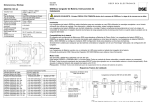
1
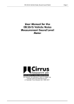
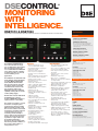
®
DSECONTROL
MONITORING
WITH
INTELLIGENCE.
®
DSE7310
& DSE7320
AUTO START & AUTO MAINS FAILURE CONTROL MODULES (COMMUNICATIONS & EXPANSION)
SPECIFICATION
DC SUPPLY
CONTINUOUS VOLTAGE RATING
8V to 35V Continuous
CRANKING DIP PROTECTION
Able to survive 0V for 50mS, providing supply
was at least 10V before dropout and supply
recovers to 5V. This is achieved without the need
for internal batteries
CHARGE FAIL/ EXCITATION
0V to 35V fixed power source 2.5W
MAXIMUM STANDBY CURRENT
160mA at 12V 80mA at 24V
MAXIMUM OPERATING CURRENT
340mA at 12V 160mA at 24V
ALTERNATOR INPUT
The DSE7310 and DSE7320 are
new control modules for single
gen-set applications. The modules
have been developed from the
successful DSE5310 and DSE5320
Series and incorporate a number
of advanced features to meet the
most demanding on-site
applications.
The DSE7310 is an Automatic Start
Control Module and the DSE7320
is an Auto Mains (Utility) Failure
Control Module. Both modules
have been designed to start and
stop diesel and gas generating
sets that include electronic and
non-electronic engines. The
DSE7320 includes the additional
capability of being able to monitor
a mains (utility) supply.
Both modules include USB, RS232
and RS485 ports as well as
dedicated DSENet® terminals for
expansion device connectivity.
The modules are simple to operate
and feature a newly designed
menu layout for improved clarity.
Enhanced features include a real
time clock for enhanced event and
performance monitoring, ethernet
communications for low cost
monitoring, mutual standby to
reduce engine wear and tear, trend
analysis to assist in the detection
of patterns in engine status and
preventative maintenance
designed to detect if engine parts
have developed fault conditions so
they can be replaced before a
major problem occurs.
FEATURES
• Backed up real time clock
• 132 x 64 pixel LCD display
• Configurable display languages
• USB connectivity
• Robust module enclosure
• Five-key menu navigation
• Durable soft touch membrane
buttons
• Fully configurable via PC software
• LED and LCD alarm indication
• Engine exercise mode
• Configurable start & fuel outputs
• kWh monitoring
• Automatic load transfer
• Eight configurable digital inputs
• Six configurable outputs
• Configurable timers and alarms
• Modbus RTU
• Magnetic pick-up
• Front panel programming
• Multiple date and time exercise
scheduler
• SMS messaging
• Power save mode
• PIN protected programming
• User selectable RS232 & RS485
communications
• DSENet® compatible
• Ethernet communications via
DSE860/865
• Customer logo display capability
• Multiple date and time
maintenance scheduler
• Configurable display pages
• Programmable load
shedding/acceptance
• Trend analysis
• Preventative maintenance
• kW overload protection
• Unbalanced load protection
• PDA compatible PC software
• Flexible sender input
• Configurable SCADA output page
NEW FEATURES
• True dual mutual standby with
load balancing timer
• Fan control for additional cooling
• ‘Protections Disabled’ facility
• Fuel usage monitoring and low
fuel alarm
• Support for up to three remote
display units
• Automatic sleep mode
• Easy access, configurable
diagnostics page shows summary
of output states
• Improved programmable event log
(250) showing date and time
• Manual fuel pump control
• Alternative configuration
• Multiple date and time scheduler
• 3 Programmable Maintenance
alarms with comms alert
• Customisable status screens
• Low fuel level alarm delay
• Charge alternator fail warning and
shutdown alarms with user
programmable delay
• Independent Earth fault trip
• Sleep mode
• Load switching (Load shedding
and dummy load outputs)
• Manual speed trim (on CAN
engines that support this feature)
• Additional display screens to help
with modem diagnostics
• Security levels – PC software has
password system to control
access to PC software features
• Operator configurable virtual LEDs
visible in SCADA
RANGE
15V - 333V (L-N) 50Hz - 60Hz
(Minimum 15V AC Ph-N)
ACCURACY
1% of full scale true RMS sensing
SUPPORTED TOPOLOGIES
3 phase 4 wire
3 phase 3 wire
Single phase 2 wire
2 phase 3 wire L1 & L2
2 phase 3 wire L1 & L3
MAINS/UTILITY INPUT (DSE7320 ONLY)
RANGE
15V - 333V (L-N) 50Hz - 60Hz
(Minimum 15V AC Ph-N)
ACCURACY
1% of full scale true RMS sensing
SUPPORTED TOPOLOGIES
3 phase 4 wire
3 phase 3 wire
Single phase 2 wire
2 phase 3 wire L1 & L2
2 phase 3 wire L1 & L3
CT’S
BURDEN
0.5VA
PRIMARY RATING
1A - 8000A (user selectable)
SECONDARY RATING
1A or 5A secondary (user selectable)
ACCURACY OF MEASUREMENT
1% of full load rating
RECOMMENDATIONS
Class 1 required for instrumentation
Protection class required if using for protection
Continued on page 2
SPECIFICATION
MAGNETIC PICKUP
VOLTAGE RANGE
+/- 0.5V minimum (during cranking) to 70V peak
FREQUENCY RANGE
10,000 Hz (max)
RELAY OUTPUTS
OUTPUT A (FUEL)
15 Amp DC at supply voltage
OUTPUT B (START)
15 Amp DC at supply voltage
OUTPUTS C & D
8 Amp 250V (Volt free)
AUXILIARY OUTPUTS E,F,G,H
2 Amp DC at supply voltage
DIMENSIONS
OVERALL
240mm x 181.1mm x 41.7mm
9.4” x 7.1” x 1.6”
PANEL CUT-OUT
220mm x 160mm
8.7” x 6.3”
Max panel thickness 8mm ( 0.3”)
TESTING
STANDARDS
ELECTRICAL SAFETY/
ELECTROMAGNETIC COMPATIBILITY
BS EN 60950
Safety of Information Technology Equipment,
including Electrical Business Equipment
BS EN 61000-6-2
EMC Generic Immunity Standard (Industrial)
BS EN 61000-6-4
EMC Generic Emission Standard (Industrial)
ENVIRONMENTAL
BS EN 60068-2-1
Cold Temperature -30oC
BS EN 60068-2-2
o
Hot Temperature +70 C
BS EN60068-2-30 HUMIDITY
Test Db cyclic
93% RH @ 40oC for 48 hours
BS EN 60068-2-6 VIBRATION
10 sweeps at 1 octave/minute in each of 3
major axes
5Hz to 8Hz @ +/-7.5mm constant displacement
8Hz to 500Hz @ 2gn constant acceleration
BS EN 60068-2-27 SHOCK
3 half sine shocks in each of 3 major axes
15gn amplitude, 11mS duration
BS EN 60529 DEGREES OF PROTECTION
PROVIDED BY ENCLOSURES
• IP65 (Front of module when installed into the
control panel with the supplied sealing
gasket)
NEMA RATING (APPROXIMATE)
• 12 (Front of module when installed into the
control panel with the supplied sealing
gasket)
BENEFITS
• 132 x 64 pixel ratio makes information easy to read
• Real time clock provides accurate event logging
• PC software is license free
• Set maintenance periods can be configured to maintain optimum engine
performance
• Ethernet communications provides advanced remote monitoring at low cost
• Modules can be integrated into building management systems
• Preventative maintenance avoids expensive engine down time
• Advanced PCB layout ensures high reliability
• Robust design
• Extensive performance monitoring
OPERATION
The modules are operated via the START, STOP, AUTO and MANUAL soft
touch membrane buttons on the front panel. The DSE7320 also has a TEST
button. Both modules include load switch buttons. The main menu system is
accessed using the five navigation buttons to the left of the LCD display.
CONFIGURATION
The modules can be configured using the front panel buttons or by using the
PC software and a USB lead.
COMMUNICATIONS
The DSE7310 & DSE7320 have a number of different communication
capabilities.
SMS Messaging
When the module detects an alarm condition, it has the ability to send an
SMS message to a dedicated mobile number (s), notifying an engineer of the
exact time, date and reason why the engine failed (GSM Modem and SIM
Card required).
Remote Communications
When the module detects an alarm state, it dials out to a PC notifying the
user of the condition (Modem required).
Remote Control
The module can be controlled remotely using either a GSM Modem, Ethernet via
DSE860/865 or via RS485. Using a modem allows the module to be controlled
from any distance. Using RS485 limits the distance to 1km (0.6 miles).
Building Management
The module has been designed to be integrated into new and existing
building management systems, using RS485.
PC Software
The module has the ability to be configured and monitored from a remote
PC, using the PC software and a USB lead.
INPUTS & OUTPUTS
Analogue inputs are provided for oil pressure, coolant temperature and fuel
level. These connect to conventional engine mounted resistive sender units
to provide accurate monitoring and protection facilities. They can also be
configured to interface with digital switch type inputs for low oil pressure and
high coolant temperature shutdowns. Eight user configurable digital inputs
are also included, plus one flexible sender.
Relays are provided for fuel solenoid output, start output and six additional
configurable outputs. On these configurable outputs a range of different
functions, conditions or alarms can be selected.
INSTRUMENTATION
The modules provide advanced metering facilities, displaying the information on
the LCD display. The information can be accessed using the five-key menu
navigation to the left of the display.
7310
7320
Generator Instruments
Volts, Hz, Amps, kW, kVA, Pf, kWh, kVAr,
kVArh, KVAh
Generator Instruments
Volts, Hz, Amps, kW, kVA, Pf, kWh, kVAr,
kVArh, KVAh
Engine Instruments
RPM, Oil Pressure, Coolant Temperature,
Hours Run, Charging Voltage, Battery Volts.
Engine Instruments
RPM, Oil Pressure, Coolant Temperature,
Hours Run, Charging Voltage, Battery Volts.
Electronic Engines
Enhanced Instrumentation and Engine ECU
diagnostics via electronic engine interface.
Electronic Engines
Enhanced instrumentation and Engine ECU
diagnostics via electronic engine interface.
Mains/Utility Instruments
Volts, Frequency, Amps (optional when
CT’s are fitted load side of the line)
ELECTRONIC ENGINE CAPABILITY
RELATED MATERIALS
TITLE
DSE7xxx Manual
DSE72xx/73xx PC
Software Manual
DSE2130 Data Sheet
DSE2157 Data Sheet
DSE2548 Data Sheet
DSE860/865 Data
Sheet
PART NO’S
057-074
057-077
053-060
053-061
053-062
055-071
DSENET®
DSENet® is a collection of expansion
modules that have been created to
work with DSENet® compatible
control modules. DSENet® allows up
to 20 different expansion devices to
be used at a time. 10 of these
devices can be of the same type
(excluding DSE2130). The expansion
modules available are:
Available Now
DSE2157 Relay Output Expansion
Module
DSE2130 Input Expansion Module
DSE2548 Annunciator Module
Remote Display Module
Coming Soon
FET Output Expansion Module
NFPA 110 Interface Module
Identification Dongle
EVENT LOG
The module includes a
comprehensive event log that shows
the most recent 250 alarm
conditions and the date and time
that they occurred. This function
assists the user when fault finding
and maintaining a generating set.
ELECTRONIC ENGINE
COMPATABILITY
• CAT
• Cummins
• Deutz
• John Deere
• MTU
• Perkins
• Scania
• Volvo
• IVECO
• Generic
• Plus additional manufacturers
®
DSE7310 & DSE7320
MECHANICAL INTERLOCK
LOAD
DSE7320 ONLY
CT’s 1 AMP OR 5 AMP
SECONDARY
PROTECTION CLASS
P1
P2
L1
L1
S1
L2
L2
L3
L3
N
N
2 AMP
FUSES
FROM
MAINS
(UTILITY)
2 AMP
FUSES
ELECTRICAL INTERLOCK
G
M
MPU
28
19
15
WL
CHARGE
ALT
CRANK
BATTERY NEGATIVE MUST BE GROUNDED
TERMINALS SUITABLE FOR 22-16 AWG (0.6mm - 1.3mm )
FIELD WIRING
TIGHTENING TORQUE = 0.8Nm (7lb-in)
47
48
49
50
R
L1
S
L2
T
L3
N
7
24
USB
PROGRAMMING PORT
ENGINE ECU
PLANT +VE
8 INPUTS
61
62
63
64
23
MPU
MAINS VOLTS
4 FET OUTPUTS
60
22
SCR
65
66
67
8
9
10
11
27
25
L
SENDER COMMON
18
30
SCR
SCR
FLEXIBLE
17
NOTE 1
FUEL
29
MODULE 7310/7320
SENDER
WATER
16
FUEL LEVEL SENDER
6
UPTO 32 AMPS
FUSE
MIN 2 AMP MAX 20 AMP
ANIT-SURGE FUSE
OIL
5
HIGH COOLANT TEMP
4
CHG ALT
3
FLEXIBLE IF
J1939 IN USE
LOW OIL PRESSURE
2
EMERGENCY STOP
1
FUEL (FLEXIBLE)
CRANK
O/P B
FUEL
O/P A
+VE
-VE
BATTERY
40
MAINS
DSE NET
LOADING
HIGH SPEED
RELAY(7320)
PERIPHERAL LINK
OUTPUT C
(ALL MODELS)
GENERATOR
LOADING RELAY
OUTPUT D
GEN VOLTS
FLEXIBLE IF
J1939 IN USE
B
39
+ -
A
SCR
42
H
41
USER CONFIGURABLE +VE OUTPUT H
57
USER CONFIGURABLE +VE OUTPUT F
L3
56
USER CONFIGURABLE +VE OUTPUT G
L2
46
N
USER CONFIGURABLE +VE OUTPUT E
GEN CURRENT
45
W
USER CONFIGURABLE -VE INPUT G
L1
RS232
44
V
USER CONFIGURABLE -VE INPUT H
U
USER CONFIGURABLE -VE INPUT F
43
USER CONFIGURABLE -VE INPUT E
54
COM
USER CONFIGURABLE -VE INPUT D
55
N
USER CONFIGURABLE -VE INPUT B
53
CT3
USER CONFIGURABLE -VE INPUT C
52
CT2
USER CONFIGURABLE -VE INPUT A
51
CT1
RS485
BATTERY
FROM
GENERATOR
S2
26
*
*NOTE 2. 120 R TERMINATING RESISTOR
MAY BE REQUIRED EXTERNALLY
SEE ENGINE MANUFACTURERS LITERATURE
NOTE 1
THESE GROUND CONNECTIONS MUST BE ON THE
ENGINE BLOCK, AND MUST BE TO THE SENDER BODIES.
THE GROUND WIRE TO TERMINAL 15 MUST NOT BE
USED TO PROVIDE A GROUND CONNECTION TO ANY
OTHER DEVICE
DEEP SEA ELECTRONICS PLC
Highfield House
Hunmanby Industrial Estate
Hunmanby, North Yorkshire
YO14 0PH England
TELEPHONE
+44 (0)1723 890099
EMAIL
[email protected]
FACSIMILE
+44 (0)1723 893303
WEBSITE
www.deepseaplc.com
Registered in England & Wales No.01319649
VAT No.316923457
DEEP SEA ELECTRONICS INC
3230 Williams Avenue
Rockford
IL 61101-2668 USA
TELEPHONE
+1 (815) 316 8706
EMAIL
[email protected]
FACSIMILE
+1 (815) 316 8708
WEBSITE
www.deepseausa.com
®
YOUR LOCAL DISTRIBUTOR.
PENDING
DEEP SEA ELECTRONICS PLC maintains a policy of continuous development and reserves the right to
change the details shown on this data sheet without prior notice. The contents are intended for guidance only.
This data sheet is printed on 9lives 55 Silk, which is produced with 55% recycled fibre from both pre
and post-consumer sources, together with 45% virgin ECF fibre.
055-051/02/09 (4)