1
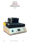
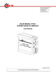
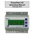
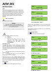
WHT200/250
INTELLIGENT ENERGY / POWER METER
INSTALLATION INSTRUCTIONS
VERSION 1 SEPTEMBER, 2014
DANGER!
•
•
•
•
•
•
HAZARD OF ELECTRIC SHOCK, EXPLOSION, OR ARC FLASH
This equipment must only be installed and serviced by qualified electrical personnel.
Read, understand and follow the instructions before installing this product.
Turn off all power supplying equipment before working on or inside the equipment.
Any covers that may be displaced during the installation must be reinstalled before powering the unit.
Use a properly rated voltage sensing device to confirm power is off.
If the equipment is used in a manner not specified by the manufacturer, the protection provided by the
device may be impaired.
DO NOT DEPEND ON THIS PRODUCT FOR VOLTAGE INDICATION
Failure to follow these instructions will result in death or serious injury.
NOTICE
• This product is not intended for life or safety applications.
• Do not install this product in hazardous or classified locations.
• The installer is responsible for conformance to all applicable codes.
For use in a Pollution Degree 2 or better environment only. A Pollution Degree 2 environment must control
conductive pollution and the possibility of condensation or high humidity. Consider the enclosure, the correct use of ventilation, thermal properties of the equipment, and the relationship with the environment.
Installation category: CAT III.
FCC PART 15 INFORMATION NOTE: This equipment has been tested by the manufacturer and found to
comply with the limits for a class B digital device, pursuant to part 15 of the FCC Rules. These limits are
designed to provide reasonable protection against harmful interference when the equipment is operated
in a residential environment. This equipment generates, uses, and can radiate radio frequency energy and,
if not installed and used in accordance with the instruction manual, may cause harmful interference to
radio communications. Operation of this equipment in a residential area may cause harmful interference in
which case the user will be required to correct the interference at his own expense.
This symbol indicates an electrical shock hazard exists.
FOR THE WHT USER MANUAL, visit www.greystoneenergy.com
NOTE: The meter is powered from a low-voltage Class 2 24VAC power source, not from the power system high
voltage. The meter could be Off (no display) and high voltage could still be present on the high voltage terminals.
Always check the high voltage wires with a voltmeter to assure that the high voltage has been de-energized
before working on the meter.
NOTE: The meter faceplate is hinged so that it can be swung out to the left for service after installation. However,
during installation, it will be most convenient for wiring the terminal blocks if the faceplate is completely
removed. The instructions below are written for complete removal of the faceplate.
MOUNTING THE METER
Mount the meter in the desired location using the screw holes in the external mounting lips on the top and bottom
of the enclosure.
REMOVING FACEPLATE AND HINGE
Open the enclosure door. Remove the two right-most screws from the metal faceplate. Remove the two left-most
screws from the plastic hinge (do not remove left screws from metal faceplate).
Swing the faceplate open and pull straight out at the hinge. The faceplate/hinge assembly should separate from the
meter enclosure. You may want to unplug the ribbon cable from the faceplate so it will be completely clear of the
work area. Let the faceplate/hinge hang from the attached green safety wire while performing the internal wiring of
the meter.
1
Installing the WHT Intelligent Energy / Power Meter
2
3
1
VERSION 4 SEPTEMBER, 2014
*For the convenience of the installer, all terminal blocks are pluggable. They can be detached from
the circuit board for wire insertion, then plugged back in when wiring is complete.
PROTECTIVE EARTH GROUND WIRE
A protective earth ground wire is required for this product. Route the protective earth ground wire in the right-most
conduit along with the high voltage system wires and connect it to the copper grounding lug on the right side of
the conduit bonding plate in the bottom of the enclosure.
HIGH VOLTAGE FIELD WIRING
Always insure that high voltage wiring is de-energized before working on the meter!
The high voltage field wiring should always be run through the right-most conduit fitting since the high voltage
terminals are located on the lower right corner of the main circuit board. Keep the high voltage leads as short as
practical inside the enclosure and dress them away from all other wiring (make any turns needed in the lower right
corner of enclosure).
Do not run any of the low-voltage control wiring or the current transformer (CT) signals in the same conduit with
the high voltage wires to avoid unwanted noise pickup.
Installing the WHT Intelligent Energy / Power Meter
2
VERSION 1 SEPTEMBER, 2014
COMMUNICATIONS ADAPTER WIRING
If the meter includes a communications adapter card, the
communication terminal blocks will be located just below
the regular control wiring terminal blocks on the left side.
Route the twisted-pair communications wiring along
the same path as the low-voltage Class 2 control wiring
as described below. If the twisted-pair communications
cable has a shield, you may optionally ground it to the
copper ground lug in the lower left corner of the main
circuit board.
CURRENT TRANSFORMER (CT) WIRING AND LOW VOLTAGE CLASS 2
CONTROL WIRING
The base WHT200 meter accepts 0.333V signals from Safe-CTs. The WHT250 meter accepts 0-5A signals from
conventional 5-amp CTs.
In both cases, the CT wires should be run by themselves in the center conduit to avoid unwanted noise pickup.
If 0.333V Safe-CTs are being used:
First, run the low-voltage Class 2 control wiring
through the left-most conduit fitting. Route the wiring
around the lower left corner and up to the control
wiring terminal blocks.
Bring the CT wiring into the center conduit fitting
and connect directly to the CT terminal block on the
main circuit board. Shielded twisted pair wiring is
recommended for Safe-CTs. If shielded wiring is used,
connect the shields to the copper ground lug in the
lower left corner of the circuit board and leave the
shields at the CT ends unconnected.
Class 2 Control Wiring
(24 VAC Power, Output Contacts, 4-20 mA)
Installing the WHT Intelligent Energy / Power Meter
3
VERSION 4 SEPTEMBER, 2014
If 5-Amp conventional CTs are being used:
Caution: conventional 5-amp CTs will produce dangerously high voltages on their secondary leads if the leads are
unterminated and the primary conductors have current flow. Before pulling CT wiring, be absolutely sure that the
primary conductors are de-energized or that the CT leads are shorted together back at the CT installation location.
First bring the low-voltage Class 2 control wiring through the left-most conduit fitting. If adapter is already
installed, remove it temporarily to make routing the control wiring easy. Route the control wiring around the lower
left corner and up to the control wiring terminal blocks.
Second remove the plug-in Safe-CT terminal block and insert the 5-amp CT adapter board in its place. Make sure
that none of the control wiring is sandwiched between the adapter board and the screw standoffs under the board.
Then secure the adapter board with two 6-32 screws (provided with adapter board).
Now run the 5-amp CT wiring through the center conduit fitting, turn the wires to the left and connect to the CT
terminal block on the CT adapter board.
Installing the WHT Intelligent Energy / Power Meter
4
VERSION 1 SEPTEMBER, 2014
Reinstalling Faceplate
When all internal field wiring is complete, grasp the faceplate/hinge assembly and guide the hinge into the molded
slot in the left side of the enclosure. Push hinge all the way into the enclosure slot.
Secure the hinge to enclosure with the two screws previously removed.
If the ribbon cable was unplugged earlier, plug the ribbon cable from the main board into the socket on the back of
the faceplate. The plug and socket are indexed so that it cannot be inserted backwards.
This completes installation of the WHT power meter.
You may now use the faceplate pushbuttons to configure the meter as desired, or plug a laptop into the Data
Port connector and download preconfigured settings into the meter (Data Port use is described in a separate
document).
REPLACING TIME & DATE BACKUP BATTERY
There is an internal battery to maintain the time-and-date in case of 24VAC power failure. This battery has an Off/On
jumper plug in the upper right corner of the main circuit board.
The meter ships with the battery installed and the battery jumper in the On position.
Should battery replacement ever be needed:
1.
2.
3.
4.
5.
Turn off high voltage to inputs.
Open meter faceplate.
Turn off 24 VAC power.
Move battery jumper to OFF.
Install new battery.
Installing the WHT Intelligent Energy / Power Meter
6.
7.
8.
9.
Restore 24 VAC power.
Move battery jumper to ON.
Close faceplate.
Restore high voltage to inputs.
5
VERSION 4 SEPTEMBER, 2014
USA: 800-561-5611 • Int’l: +1-506-853-3057 • www.greystoneenergy.com
© 2014 Greystone Energy Systems. Inc. All rights reserved. The Greystone name and logo are registered trademarks of
Greystone Energy Systems, Inc.