1
PatternMaker Software
PatternMaker Version 6
TUTORIALS
PatternMaker for Windows
for PC-compatible computers running Windows 95 and higher
Version 6
PatternMaker Software
PO Box 70306
Bellevue, WA 98007
(425) 644-8161
Authors: Brian Pickrell, Jim Pickrell, Tamara Vlasuk
Revised 2/00
Copyright 1994-2002 by PatternMaker Software.
All rights reserved. No part of this manual shall be reproduced, stored in a retrieval system, or transmitted by
any means, electronic, mechanical, or otherwise, without permission from PatternMaker Software, with the
exception of quoting brief passages for the purpose of reviews.
Table of Contents
PREFACE TO TUTORIALS ............................................................................................ 1
TUTORIAL 1: GETTING PATTERNMAKER STARTED................................................. 3
Part 1: Installing PatternMaker ................................................................................................3
Part 2: Running PatternMaker..................................................................................................6
TUTORIAL 2: OPENING A DRAWING AND VIEWING IT............................................ 10
Open a drawing ............................................................................................................................10
TUTORIAL 3: ENTERING INPUTS............................................................................... 13
Absolute coordinates....................................................................................................................13
Relative coordinates.....................................................................................................................14
Relative angle (polar coordinates)..............................................................................................15
Save your drawing .......................................................................................................................16
TUTORIAL 4: THE EDIT FUNCTIONS ......................................................................... 18
Moving objects .............................................................................................................................18
Selecting objects ...........................................................................................................................18
Undo a change ..............................................................................................................................20
Repeat a command.......................................................................................................................20
Grouping objects ..........................................................................................................................20
Ungrouping objects ......................................................................................................................21
More editing commands ..............................................................................................................21
Still more editing commands.......................................................................................................22
Cancel a command .......................................................................................................................22
Restoring a Drawing from Disk..................................................................................................22
TUTORIAL 5: CUT, JOIN, AND SNAP POINTS........................................................... 24
Draw a line....................................................................................................................................24
Snap to Ortho ...............................................................................................................................24
Cutting an object..........................................................................................................................25
Snap to Grid .................................................................................................................................26
Joining two objects.......................................................................................................................27
Placing a point on a curve (optional)..........................................................................................28
TUTORIAL 6: POINT EDIT FUNCTIONS ..................................................................... 30
Move a vertex ...............................................................................................................................30
Changing the shape of an arc......................................................................................................31
Selection windows ........................................................................................................................32
TUTORIAL 7: POLYGONS, TEXT AND DIMENSION OBJECTS WITH COLORS AND
FILL PATTERNS........................................................................................................... 35
Setting the drawing color ............................................................................................................35
Setting the fill pattern..................................................................................................................35
Creating a dimension line............................................................................................................36
Creating text .................................................................................................................................38
TUTORIAL 8: INTRODUCTION TO GRADING – THE RECTANGLE .......................... 40
Creating a grading rule ...............................................................................................................40
Create a grading table .................................................................................................................42
Grading a pattern ........................................................................................................................44
TUTORIAL 9: LAYERS ................................................................................................. 46
Changing the current layer .........................................................................................................47
Changing a layer name ................................................................................................................47
Changing a layer's default color.................................................................................................47
Turning layers on and off............................................................................................................48
Resetting the layers ......................................................................................................................48
TUTORIAL 10: SYMBOLS AND LIBRARY FILES ....................................................... 50
Selecting a symbol library ...........................................................................................................50
Loading a symbol .........................................................................................................................51
Creating or redefining a symbol (Expert or Marker Versions only) ......................................52
Creating a symbol library ...........................................................................................................54
The Explode command ................................................................................................................54
TUTORIAL 11: OFFSETS, SEAM ALLOWANCES, AND FACINGS............................ 56
Variable seam allowance .............................................................................................................56
Change the line style ....................................................................................................................57
Snap to Offset ...............................................................................................................................58
Single seam allowance..................................................................................................................60
TUTORIAL 12: MARKERS ........................................................................................... 62
Setting the Cut Ratio....................................................................................................................62
Define Marker Pieces...................................................................................................................63
Marker Mode ...............................................................................................................................63
Set Marker Area ..........................................................................................................................64
Multiply by Cut Ratio..................................................................................................................65
Arranging a Marker ....................................................................................................................65
Marker Report .............................................................................................................................68
Printing a Marker ........................................................................................................................69
WEB PAGE TUTORIALS.............................................................................................. 71
Elementary Tutorial #1 ...............................................................................................................73
Elementary Tutorial #2 ...............................................................................................................95
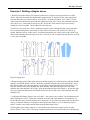
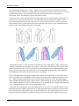
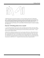
Advanced Tutorial: Design Exercises ......................................................................................116
Advanced tutorial: Grading......................................................................................................147
INDEX ......................................................................................................................... 151
PREFACE TO TUTORIALS
Welcome to the convenience of PatternMaker Software! These tutorials will help you get started with
PatternMaker computer-aided design.
Work through the tutorials in order. Read the sections in the manual that apply to the subjects the
tutorials are covering, too. The tutorials give you a way to get started very quickly in PatternMaker, but
they don't give a complete explanation of they subjects they cover.
TUTORIAL CONVENTIONS
As you work through these tutorials, you will notice that some words or phrases appear in different
typefaces. Here's what it all means:
Anything you should type will be in boldface print. The names of special keys, such as the "Enter" key
("Return" on some keyboards), are set aside in angle brackets. For instance:
Press <ENTER>
Anywhere you see two special keys listed together, such as
<CTRL>+<F1>
you need to hold down the first key while typing the second.
Instructions that you should do, but that aren't meant to be typed verbatim into the computer, are set aside
in square brackets:
[Select point with mouse]
Messages that you will read on the screen are printed in Courier type (a font that looks like a typewriter):
Message from PatternMaker:
Sometimes a tutorial will tell you to do something that can be done in more than one way. For instance,
many commands can be selected either from a menu or by selecting an icon. If you know a different way
to do something, you don't have to do it exactly the way the tutorial says. When in doubt, however,
follow the directions exactly.
Note on the "Escape" key: In PatternMaker, the right mouse button has the same effect as the Escape key
(<ESC>) and it's usually more convenient to use. For brevity, the tutorials will often tell you to use the
Escape key, but you can use the right mouse button instead.
What to do if you get stuck:
•
Make sure you are using the correct button of the mouse. If you have a three-button mouse,
PatternMaker will ignore the middle button.
1
Preface to Tutorials
2
•
Read the prompt line. See what question the computer is asking. The computer may not
understand what you are trying to do, or it may be doing a different command than you think it
is. If you want to do a new command you may need to end the current command. Try pressing
the <ESC> key a couple of times.
•
Holding the mouse down and “dragging”, as done in many programs where accuracy isn’t
required, doesn’t work in PatternMaker. Use mouse clicks. For example, to draw a line click
once at each end.
•
If all else fails, read the manual. You will be pleasantly surprised at the wisdom it contains.
The only purpose of the manual is to help you use the program, so don’t be afraid of it!
TUTORIAL 1: GETTING PATTERNMAKER STARTED
If you are used to running programs in Windows, the first part of this tutorial will be familiar to you. If
you have purchased the entire PatternMaker system, PatternMaker is installed on the computer when you
get it and you can skip the installation. If you know how to run other programs in Windows, you can
start using PatternMaker right away because most basic operations, such as opening a file or selecting a
command, work the same way for PatternMaker as for other Windows programs.
PART 1:
INSTALLING PATTERNMAKER
This tutorial assumes that you will install PatternMaker on your C: drive, in a directory called
C:\Program Files\PatternMaker Software\PatternMaker
and that your CD drive is the D: drive. If your computer is set up differently, you should already know
about it and you can modify your commands accordingly.
Installation of PatternMaker is easy. Just follow these simple steps:
RUN THE CD BROWSER
Put the PatternMaker CD in your CD-ROM drive. If your system is set up to run CDs automatically, you
can skip to the section called “Install Components From Browser” now. If not…
Click the Start button on the taskbar, then click "Run…" and type
[Click “Start” button]
[Click “Run…]
d:demo32.exe.
(If your CD drive is not drive D:, substitute the appropriate letter.) Click the “OK” button.
[Click “OK” button]
A file dialog box opens. Select the file “pat32-ver4.dbd” and click “Open.” This runs the PatternMaker
CD browser.
[Select file PAT32-VER4.DBD]
[Click “Open” button]
The main menu of the CD browser will be displayed.
INSTALL COMPONENTS FROM BROWSER
Click the button labeled “Install Products”
[Click “Install Products” button]
Now you see the Installation menu. Move the mouse over the buttons and notice that you get a
3
Tutorial 1: Getting PatternMaker Started
description of what each button does. There are several things here you can install, but for now we’re
only concerned with the PatternMaker program and perhaps a garment collection.
Move your mouse over the button to the right of the words “PatternMaker Version 4.” After you’ve read
the description, go ahead and click the button.
[Click button labeled “View Options”]
There are two options for installing the PatternMaker program. Choose one now:
1) IF YOU ARE USING THE DEMO:
Click the button to the right of the words “Program With Demo Macros.”
[Click button labled “Install Now”]
This will launch the PatternMaker Setup program. Setup installs PatternMaker and a set of demo
macros onto your hard drive.
Skip now to the section below called “Install PatternMaker.”
2) IF YOU ARE USING A PURCHASED VERSION:
Click the button to the right of the words “Program Only (No Macros)”
[Click button labled “Install Now”]
This will launch the PatternMaker Setup program. Setup installs the PatternMaker program only
onto your hard drive. We will be installing the macros (garment collections) in a later step.
Continue now to the section below called “Install PatternMaker.”
INSTALL PATTERNMAKER
The first screen you see is a Welcome message. Read it, then click the “Next” button.
[Click the “Next” button]
The next screen asks where you want PatternMaker to be installed. By default, PatternMaker expects to
find all necessary files in the folder called
C:\Program Files\Patternmaker Software\PatternMaker
If this is okay, click the “Next” button. We recommend that you do this. If you prefer to install
PatternMaker in a different folder or on a different drive, click the “Browse” button and specify the
proper folder.
[Click the “Next” button]
The next screen is asking about creating a folder on your Start menu. The default is to create a folder
called “PatternMaker.” Again, we recommend that you accept this default, and click the “Next” button.
4
Tutorial 1: Getting PatternMaker Started
[Click the “Next” button]
The final screen confirms the information you have entered. Click the “Next” button one more time to
begin copying the files to your hard drive.
[Click the “Next” button]
After the files have been copied, you will see a message that the setup process is complete. You will
have the option of running PatternMaker immediately, but you don’t want to do this just yet. Leave the
check box blank (unchecked) and click the “Finish” button.
[Click the “Finish” button]
You will now return to the CD brower.
RETURN TO CD BROWSER
Again, you have a choice to make, depending on whether you are using the demo or purchased version of
the program:
1) IF YOU ARE USING THE DEMO:
If you’re using the demo, you’re done with the installation! Exit the CD browser:
[Click the button labled “Main Menu”]
[Click the button labled “Exit”]
[Click the button labled “Exit”]
Continue with the tutorial by skipping to the section below called “Running PatternMaker.”
2) IF YOU ARE USING A PURCHASED VERSION:
Your final step is to install any garment collections (macros) that you have purchased. You may
have purchased macro sets alone, or you may have the Women’s Vol. 1 which comes with the
Home, Expert and Marker versions.
Go back to the Installation menu:
[Click the button labled “Return To Installation Menu”]
Click the button to the right of the words “Add-On Garment Collections”
[Click the button labled “View Options”]
Click the button corresponding to the macro collection(s) you have purchased.
[Click button labled “Install Now”]
5
Tutorial 1: Getting PatternMaker Started
Confirm the folder where the macros will be installed. The default for the macros is the same as
the default for the PatternMaker program. We recommend that you accept the default.
[Confirm installation path]
[Click the “Unzip” button]
Each macro collection is protected by a password. Your PatternMaker package includes a piece
of paper with the password printed on it. Use this to install the macros.
Note: the macro passwords are case-sensitive, and must be entered exactly as shown.
[Enter macro password]
[Click the “OK” button]
The macros will unzip, and you will see a message box with a confirmation. Click “OK” then
close the Unzip dialog box, if it is still open.
[Click “OK” button]
[Click “Close” button]
You will now return once again to the CD browser. Exit the CD browser:
[Click the button labled “Main Menu”]
[Click the button labled “Exit”]
[Click the button labled “Exit”]
Continue with the next section called “Running PatternMaker.”
PART 2:
RUNNING PATTERNMAKER
After you have installed PatternMaker, you start it, like any other Windows program, by selecting its icon
from the Start/Programs menu.
[Select Windows “Start” button on the taskbar]
[Select “Programs”]
[Select “PatternMaker”]
[Select PatternMaker icon (labled “Pat32”)]
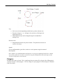
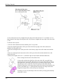
As with any Windows program, a new “window,” or rectangular area on the screen, appears when you
start PatternMaker. At the very top of the new window is a title bar with the words
PatternMaker
6
Tutorial 1: Getting PatternMaker Started
On the far right end of this title bar are three small squares. The title bar and squares, or “buttons,” are
also standard for all Windows programs. The functions of these buttons, from left to right, are as
follows:
minimize window
maximize window
exit the program
EXPAND THE PATTERNMAKER WINDOW TO FULL SIZE
The program should have opened with the PatternMaker window filling the entire screen. If it did not,
move the mouse to put the cursor on the center button on the title bar, the one with a small square. Click
the left mouse button.
[Click Maximize button]
The PatternMaker window expands to fill the entire screen. Windows gives all programs the ability to
run in either a partial or full screen, but you will always want to use the full screen for PatternMaker.
Remember to do this every time you start PatternMaker.
When the word
Command:
appears at the bottom of the screen, PatternMaker is ready to go. Move the mouse around on the table.
The cursor (a little arrow) will move around on the screen.
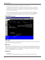
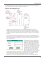
WHAT YOU WILL SEE
Most of the screen will be black. This is the drawing area. It won't always show the whole drawing,
because with PatternMaker you can zoom in and out and pan, like a movie camera.
On the left side of the screen are the icons. These look like little pictures. Each one represents a
command. If you put the cursor on an icon and click the left mouse button, the command will run. If you
move the cursor over an icon but don’t click the mouse, you’ll see a pop-up hint that tells you the name
of the command the icon represents. If you click the right button, PatternMaker will show you a help file
that tells you about the command.
At the top of the screen is a white bar with words on it. This is the menu bar. Each word represents a
menu – a list of commands. To see a menu, put the cursor on one of the words and click the left mouse
button. To hide the menu again, click the left button again somewhere away from the menu.
Below the menu bar is a black bar with words
Draw Mode
Layer0
some colored boxes, and some numbers. (“Draw Mode” won’t be here if you have PatternMaker Home
or Expert version.) This is the status bar. The words and colored areas work just like icons, but you can
ignore them for now. The numbers indicate the position of the mouse. They are the x and y coordinates
of the cursor position. Notice that they change as you move the mouse.
7
Tutorial 1: Getting PatternMaker Started
You can do your work in PatternMaker in either inches or centimeters. The mouse coordinates will
appear in whichever units you have selected. In Tutorial 2 we'll talk about how to change the units.
At the bottom of the screen is a blue bar with white printing in it. This is the prompt line. Look at it
frequently when you are using PatternMaker. It will give you messages, or prompts, telling you what you
are doing and what you need to do next. Remember that the prompts scroll – this means that the bottom
message is the most recent. Right now the prompt should be
Command:
You will see this prompt every time you finish a command and PatternMaker is waiting for a new
command. Anything you type into the computer will also appear in the prompt line.
RUN A COMMAND
Put the cursor on the icon that looks like a rectangle. Click the left mouse button. You will see a
prompt:
Command:RECT
Enter a point, <ESC> to cancel:
You are now running the rectangle command. Notice that the word
RECT
appears in green letters at the right end of the status bar. This area always tells you what command you
are running.
Now, move the cursor into the drawing area and click the left button again. Important: don't hold the
button down. PatternMaker does not use the "click and drag" system that many other computer programs
use.
[Select a point with mouse]
You have just entered a point into your drawing. There are other ways to do this, which you will learn in
future tutorials, but clicking the mouse on the drawing area is the most basic way to give PatternMaker
data.
Move the mouse around the drawing area. A rectangle will follow it around. Click the left button again.
[Select a point with mouse]
You have just drawn a rectangle. You know you are done with the command because you see the
prompt:
Command:
and the word RECT changes from green to purple in the status bar.
8
Tutorial 1: Getting PatternMaker Started
REPEAT A COMMAND
Click on a different point in the drawing area. PatternMaker will start the Rectangle command and use
this point as the first input. Click on a different point in the drawing area to finish the rectangle.
[Select a point with mouse]
[Select another point with mouse]
Look for the prompt:
Command:
on the command line again.
RUN A COMMAND FROM THE MENU BAR
You will now leave PatternMaker by running the EXIT command. Put the cursor on the word "File" in
the menu bar and click the left button.
[Select File menu]
A menu will appear. Look for the word "Exit." Note that the letter x is underlined. Type
X
and PatternMaker will run the Exit command. Before the program ends, a box will appear, asking the
question
Save file NONAME.PAT?
Put the cursor on the word "No" and click the left button.
[Select "NO" button]
You have finished running PatternMaker.
Now that you know how to run PatternMaker and give commands, the other tutorials will teach you how
to use those commands.
9
TUTORIAL 2: OPENING A DRAWING AND VIEWING IT
This tutorial shows you how to look at an existing PatternMaker drawing, either one that came with the
PatternMaker package or one that you have created yourself. You will not draw or change anything in
this tutorial.
ZOOM and the related commands can be run by pressing some of the special keys on your keyboard.
You can do this at any time – even if you're in the middle of running a different command. Therefore,
these keys are known as “hot keys.” You will find this is very important when you are adding to or
changing a drawing.
If you don't have PatternMaker running already, start it as you did in Tutorial 1.
OPEN A DRAWING
Use the mouse to select the File menu, and select the OPEN command from this menu. Press the
<RETURN> or <ENTER> key.
[Select File-Open]
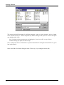
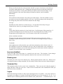
A dialog box will appear. In the largest white area will be a list of all the PatternMaker for Windows
drawing files in this directory. This list will look something like this:
G0641.PAT
LIBRARY.PAT
..
SUBDIR\
but it will probably be longer, depending on how many drawing files you have.
Each name ending in ".PAT" is the name of a drawing file. Use the mouse to highlight the name of a
drawing file you would like to look at. Press the <RETURN> or <ENTER> key.
[Select file G0641.PAT] <RETURN>
You will see a pattern appear in the drawing area.
You can read more about using the file selection box in Chapter 3 of the manual. If you don’t understand
the organization of files on the disk, you may want to refer to a book which explains Windows concepts
in detail.
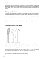
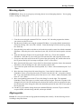
ZOOMING
Try using some of the function keys to change your view of the drawing: Take the overlay (the long thin
plastic-coated strip) out of your PatternMaker package and put it across the top of your computer
10
Tutorial 2: Opening A Drawing And Viewing It
keyboard. It shows you what each special key does. Find F1 on the overlay; just above it it says "Zoom
Out." Press
<F1>
and the whole drawing will get smaller. The drawing itself hasn't changed, but your view has zoomed out
like a movie camera. Press
<F2>
to zoom back in. Now put the mouse cursor on a part of the drawing you would like a closer look at.
Press <F3>
[Position mouse cursor]
<F3>
and the view will zoom in on that spot.
PANNING
<Arrow key>
The arrow keys will move your view left, right, up, or down without changing the size of the picture.
Use any or all of the following keys a few times, to get a feel for them:
<F1> <F2> <F3> <F9> <PG UP> <PG DOWN> <HOME> <END> <↑
↑><↓
↓> <←
←> <→
→>
When you are done, press
<END>
This is the ZOOM ALL command and it centers the entire drawing in the drawing area.
OTHER FUNCTION KEYS
<F4>
will display the grid. The dots you see are one inch or one centimeter apart (until you set
them to something different). If no dots appear, you need to zoom, either in or out, until
the dots appear. Pressing the <F4> key again will hide the grid.
<F5>
will display the vertices that the objects in your drawing are made up of. An "X" appears
at each vertex. Pressing <F5> again will hide the vertices.
<F7>
will hide or show the grading arrows in your drawing, as well as their names. There
probably aren’t any grading arrows in your drawing. Don't worry about it for now.
11
Tutorial 3: Opening A Drawing And Viewing It
Other F keys have functions that don't change the way your drawing looks on the screen. You will learn
about these later.
You can also perform most of the same zoom functions by clicking the mouse on the zoom icons that
appear when you are running other commands. The next tutorial lets you practice this.
CHANGE YOUR WORKING UNITS
When you first start PatternMaker, the program is set to work in inches. However, if you prefer to work
in centimeters, it's easy to change. Click on the box that shows the mouse coordinates (you learned
where this is in Tutorial 1).
[click on mouse coordinates]
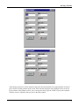
A dialog box will open, showing a list of measurement units you can choose from. Select "centimeters"
and then click the "OK" button.
[select "centimeters"]
[click "OK" button]
Now, as you move the mouse around, the position of the cursor is indicated in centimeters rather than
inches. Turn on the grid, if it isn't on already.
<F4>
The dots you see are one centimeter apart. (Use <F1> or <F2> to zoom in or out, if you can't see any
dots.)
Since the rest of these tutorials use inches, go ahead and change back. As you do, pay attention to what
happens to the grid.
[click on mouse coordinates]
[select "inches, no fractions"]
[click "OK" button]
Notice how the grid adjusted, so that the dots are now one inch apart, instead of one centimeter apart.
You will have noticed that there are several other measurement format options in the list. We won't
discuss all of these now, but you can experiment with them later if you wish. The differences are
explained in detail in the User's Manual.
Now you know how to zoom in on a detail, or zoom out to see your whole pattern. You can use the grid
to see how big something is, and you can see the vertices if you need to change some of them.
You are now done with this tutorial. You can Exit the program, use OPEN to open a different drawing
file, or use the NEW command to prepare for the next tutorial.
12
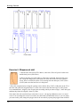
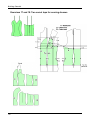
TUTORIAL 3: ENTERING INPUTS
In Tutorial 1 you input the corners of a rectangle by clicking the mouse on the screen. This is the easiest
way to give PatternMaker inputs. In this tutorial, we will see how to use typed inputs to enter your points
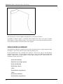
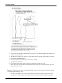
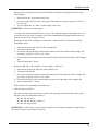
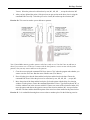
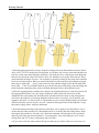
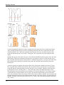
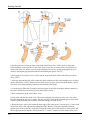
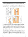
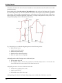
more precisely. We will draw a sloper: a basic size 12 back body block.
Note: this tutorial is to teach you how to enter inputs to PatternMaker; we won't be learning standard
pattern drafting techniques. The numbers you will be given were precalculated; so don't be concerned if
they seem mysterious.
First, we will draw a rectangle to form a frame for our drawing. Start PatternMaker and select the RECT
(rectangle) command.
[Select RECT icon]
ABSOLUTE COORDINATES
Use x and y coordinates to enter the corners of the rectangle. Type
0,0 <ENTER>
for your rectangle's first point. (The first number is the horizontal, or x, coordinate. The second is the
vertical, or y, coordinate.)
Type
12,26 <ENTER>
for the second point. At this point, your prompt line will look like this:
Enter a point, <ESC> to cancel:0,0
Second point, <ESC> to cancel:12,26
Command:
TO SEE THE FULL DRAWING
You can't see much because the rectangle is mostly off the edge of the screen. Press
<END>
to center the rectangle in the drawing area. The lower left corner of the rectangle is at the origin,
coordinates (0,0). You can check this by putting the cursor on this point and looking at the mouse
coordinates. Don't worry if it isn't exact; your typed inputs are more precise than pointing with the
mouse.
13
Tutorial 3: Entering Inputs
The upper right corner of the rectangle is at (12,26). This means it is 12 inches to the right of the origin
and 26 inches above it.
Now start drawing the sloper, using the POLY command. The POLY icon looks like a pencil drawing
some lines. Click on it to start the POLY command.
[Select POLY icon]
ZOOMING AND PANNING WITH ICONS
Notice that the icons in the icon area have changed. The icons containing yellow x’s change snap modes,
which are covered in Tutorial 5. The ones showing a movie camera and an arrow are the pan functions;
the ones with arrows going in or out are zoom functions. Click the mouse on the icon with a rectangle
and an arrow pointing left.
[Select Pan Left icon]
Now pan right, so the view goes back to where it was.
[Select Pan Right icon]
You can experiment with the other zoom and pan icons on your own.
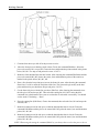
Now, let’s start drawing the object. For the first point, type
1,1 <ENTER>
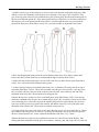
RELATIVE COORDINATES
We want to draw a line up the center back seam. This length is 23.75 inches. You don't want to measure
from the origin; you want to measure from the point you just entered, so type the relative coordinates:
@0,23.75 <ENTER>
The 0 means the x distance from the first point is 0. The 23.75 means the new point is 23.75 inches
above the previous point.
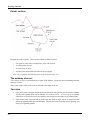
DRAW A CURVE
Now draw the neckline. Press
<ESC>
and a box will appear, titled
"Point Type Options"
14
Tutorial 3: Entering Inputs
Click the left mouse button on the line that says "Arc(X)"
[Select "Arc(X)" from box]
and you will get the prompt messages
Input next point, ESC for options Option:X arc
Input corner point of arc, ESC for options
The corner point controls the shape of a curved line. This can't be measured precisely, but you can do it
"by eye." Turn the grid on.
<F4>
and use the mouse to enter a point about 1½ inches to the right of your last point and level with it. Or
type the absolute coordinates:
2.5, 24.7 <ENTER>
Move the mouse around now, and you can see a curve following it. This is the curve that will be drawn
if you click the left mouse button. Instead, enter the end point by typing its absolute coordinates:
3.25, 25.5 <ENTER>
This is the point where the neck meets the shoulder. It is 2 - 1/4 inches to the right of the start of the
neck curve and 3/4 inch above it.
Now we need to draw a straight line for the shoulder line. Select the "Line" point option:
<ESC>
[Select "Line"]
RELATIVE ANGLE (POLAR COORDINATES)
Instead of relative x and y coordinates, you can enter a point by giving a distance and angle. The
shoulder line is 5¾ inches long, and it slopes downward at a 22 degree angle. Angles are measured
upwards from the horizontal. For instance, an angle going straight up would be 90 degrees. Since our
line goes down, its angle is -22 degrees. Use the "less-than" symbol < to indicate that the numbers you
type in represent an angle:
@5.75<-22 <ENTER>
The @ means that this, too, is a relative position.
To complete the sloper, type in the following points and select point type options where indicated:
15
Tutorial 3: Entering Inputs
<ESC>
[Select "Arc(X)"]
8, 21.75 <ENTER>
8.25, 18.36 <ENTER>
8.50, 15.90 <ENTER>
10.50, 15.60 <ENTER>
<ESC>
[Select "Line"]
10.50, 1 <ENTER>
<ESC>
To finish drawing this object, you can select either Open or Closed from the box. A closed polygon is
just like an open one, except that a line is drawn connecting the first and last points. This sloper is a
closed object. Click on the words “Done (closed)”
[Select “Done (closed)”]
to finish the command.
If you make a mistake and you get a sloper that doesn't look very good, it's okay to keep it and use it for
the rest of the tutorials. If you make a more serious mistake (such as accidentally cancelling the POLY
command), you will probably need to start the tutorial over. There are ways to fix a mistake with
PatternMaker, but you haven't learned them yet.
LINE
Mark the waistline of this sloper. Select the Line icon (a diagonal line). Type in two points:
[Select Line icon]
1, 7.75 <ENTER>
10.50, 7.75 <ENTER>
The endpoints of this line will fall exactly on the sides of the sloper.
SAVE YOUR DRAWING
Select the SAVE command from the File menu.
[Select File-Save]
The prompt will read,
16
Tutorial 3: Entering Inputs
SAVE
and a dialog box will appear, with the names of all the existing drawing files. Don't select any of these.
Instead, type
BACKSLOPER <ENTER>
and PatternMaker will save your drawing in a new file called BACKSLOPER.PAT. You can give a file
any name you want. You don’t need to type the “pat” extension; PatternMaker adds that automatically.
Don't save a drawing with a name that already exists, unless you want your new file to replace the old
one with the same name. If you do this, the previous file will be saved in a file with the extension
".BAK", for instance BACKSLOPER.BAK, but if you do it twice, the old ".BAK" file will be lost.
If your drawing already has a name other than "NONAME.PAT," you can save it with the same file
name. In this case the previous version of the drawing will be replaced. This is how you will save
changes to this file in the following tutorials.
You are now done with Tutorial 3. Next, you will learn ways to add to and change your drawing.
17
TUTORIAL 4: THE EDIT FUNCTIONS
In Tutorial 3 you drew a sample pattern piece consisting of two objects. In this tutorial you will use
some of the editing functions to modify your sloper. You will sample some of the functions in the Edit
menu, which work on entire objects. The functions in the Points menu are also editing functions, but
they work on some of the individual points in an object, rather than the whole object. You will try some
of these later.
Start PatternMaker and open the file BACKSLOPER.PAT that you created in Tutorial 3. You should see
the sloper object, the horizontal waist line you drew, and the box around them. If you don't, press
<END>
to put them in view.
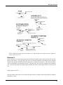
MOVING OBJECTS
Select the Move icon. It looks like a hand. Click the left mouse button on it. (The MOVE command is
also in the Edit menu.)
[Select Move function]
In the prompt window you will see:
Select object, ? for help, <esc>=done:
This message appears whenever you are running a command that needs you to select one or more objects.
SELECTING OBJECTS
Important: Knowing how to select an object or objects is very
important in PatternMaker. In future tutorials, you will often be
told to select objects. Practice the following procedure until you
are comfortable with it. Read the manual paragraphs on selecting
objects (Chapter 4). They give more details than are included
here.
Put the mouse cursor on or near the sloper object and click the left button.
[Select sloper object]
Make sure to click on one of the white lines, not in the center of the object. The object will highlight (a
highlighted object is drawn in thicker lines) and the prompt will now say,
18
Tutorial 4: The Edit Functions
Select object, ? for help, <esc>=done: *Polygon selected*
If nothing happens, you didn't click the mouse close enough to the edge of the object. If the wrong object
highlights, click on it again and it will be un-selected. Then select the sloper object.
Note that the line inside the sloper is not highlighted. This is because it is a different object and you
haven't selected it yet. We want the waistline to stay with the sloper when we move it, so select the line
too.
[Select horizontal line]
The computer will keep asking you to select more objects until you tell it you're done selecting. You
should now have both the sloper and the line highlighted. Tell the computer you're finished selecting
objects by pressing the Escape key.
<ESC>
The prompt line will now say
Select object, ? for help, <ESC>=done: *Polygon selected*
Select object, ? for help, <ESC>=done: --OK-Base point?:
PatternMaker is asking you for a reference point to calculate the movement from. Think of it as a handle
that you are attaching to the objects to carry them by. But the handle doesn't have to be on the objects
you're moving – it can be anywhere in the drawing.
Use the left mouse button to select a point somewhere near the objects you have selected.
[Select a base point]
The next prompt will be
Destination (ESC to quit):
Move the mouse around. Remember not to hold the mouse button down. The objects you selected will
move around, too. You will see a blue-green, or cyan, line appear. This line indicates how far you have
moved the objects and is not part of the drawing. Move the mouse to the right a bit, then click the left
button.
[Select destination point]
The cyan line disappears and the word
Command:
appears on the prompt line, showing that you are done with the MOVE command.
19
Tutorial 4: The Edit Functions
The objects have moved a distance equal to the distance from the base point to the destination. For
instance, if the destination is three inches to the right of the base point, the objects will have moved three
inches to the right.
Any of the points you just entered could have been selected by typing the coordinates, as you learned to
do in Tutorial 3. This would give you precise control over the distance your objects moved.
UNDO A CHANGE
Suppose the MOVE command you just did was a mistake. You can use the UNDO command to undo the
last change you made to the drawing. Select the Undo icon now (it looks like a letter U).
[Select Undo function]
The objects you just moved will move back to their original positions. Remember that you can't undo
more than one command in a row, so if you make a mistake, select the UNDO command before you do
anything else.
REPEAT A COMMAND
If you want to do the MOVE command again, you don't need to select the Move icon again. Just click
the mouse anywhere in the drawing area. The MOVE command will be selected again and it will start
selecting objects. Go ahead and move the same two objects anywhere you like.
[Select and move sloper and line]
GROUPING OBJECTS
Sometimes you have a group of objects and you will want any change made to one of them to apply to all
of them. In other words, when you select one, you want to select all of them. You can do this by
forming a group. The GROUP command is found in the Symbol menu.
[Select Symbol-Group function]
Select the same two objects you selected before.
[Select sloper and line]
<ESC>
You are then prompted for a name for the group. You need to give a group a name if you plan to use the
Load From Library function (Tutorial 10) to load it into another drawing later. Don’t give this group a
name; just click the “OK” button.
[Click “OK” button]
20
Tutorial 4: The Edit Functions
You have just made a group of the sloper and the line. Now, select the MOVE function and then select
the sloper object.
[Select Move function]
[Select sloper object]
When you do this, the line is selected and highlighted as well. We don’t really want to move these
objects, so cancel the MOVE function.
<ESC> <ESC>
UNGROUPING OBJECTS
To break the group up again, use the UNGROUP command in the Symbol menu.
[Select Symbol-Ungroup function]
[Select sloper group]
<ESC>
Now, the sloper and the line are independent objects again.
MORE EDITING COMMANDS
Try the following commands from the Edit menu. All of them work in a way similar to MOVE. The
steps you follow are:
1. Select a command.
2. Select objects by clicking the left mouse button on them.
3. Press <ESC> or click the right mouse button to finish selecting objects.
4. Give PatternMaker more information, either by entering points with the
mouse, making choices when asked, or typing inputs.
5. You can repeat a command by clicking the mouse in the drawing area
again.
Read the manual sections on these commands for an explanation of each one. Like MOVE, some of
these commands move objects around as you move the mouse. You can get a general idea of their effects
by just watching what happens as you move the mouse. Don't worry about making a mess of the drawing
– you will see how to restore your drawing later in this tutorial.
ROTATE
rotates a group of objects.
RESIZE
makes objects larger or smaller. It can also change their shapes by resizing
differently in the X and Y directions.
21
Tutorial 4: The Edit Functions
EXPAND
makes objects larger or smaller. Unlike RESIZE, it doesn't change the shape of an
object.
ERASE
erases objects from the picture.
COPY
copies one or more objects. It's just like MOVE, except that you end up with an
object at the destination and an identical one in the original position.
MIRROR
makes mirror-image copies of objects. The line that follows the mouse after you
select the object(s) represents the "mirror" across which the originals are reflected.
STILL MORE EDITING COMMANDS
Try the following commands, too. There won't be anything to watch as you move the mouse, but they are
even simpler than MOVE.
CHANGE
changes the color, fill pattern (for closed objects only), layer, (we will learn about
layers later) or line type (dotted line, etc.) of the selected objects. Try changing the
color of some objects for starters.
CLOSE OBJ converts an open object to a closed object by connecting the two ends of the object
with a line. Use the POLY command to draw an open object before you can try this.
The opposite of this command is DELETE SEG., found in the Points menu.
CANCEL A COMMAND
Remember that pressing <ESC> or clicking the right mouse button while you are in the middle of a
command aborts the command. Try this while moving some objects. They will jump back to their
original positions and you will be prompted to select a new command. (Since many commands have
intermediate steps, sometimes you’ll need to press <ESC> more than once. This depends on the
command you are using.)
We will cover the CUT and JOIN commands in Tutorial 5.
RESTORING A DRAWING FROM DISK
If you have experimented with all of the commands listed above, your drawing is probably a cluttered
mess now. Any time you do some work, then decide you want to have your original drawing instead, you
can reload your drawing from the file it is saved in. Select the OPEN command from the File menu.
[Select File - Open]
A dialog box will appear, saying
22
Tutorial 4: The Edit Functions
Save file
C:\Program Files\PatternMaker Software\PatternMaker\BACKSLOPER.PAT?
YES
NO
CANCEL
You don't want to save the changes you just made, so select the “No” button with the mouse.
[Select "NO" button]
The computer now deletes your drawing from memory, but the original version is still in the file. The
box with the file names now appears, just as it did at the beginning of this tutorial. Select the same file
you selected before.
[Select file BACKSLOPER.PAT]
You will see the same drawing you saw the first time you opened the file. You should use the SAVE
command periodically while you are working, to save your latest changes. Then, when you reopen your
drawing as you just did, it will return to the way it was the last time you ran the SAVE command.
You have now finished Tutorial 4. You now know how to copy, move and rearrange the objects in your
pattern. You also know how to save your work, and how to retrieve your saved work if necessary. In
Tutorial 5 you will use the CUT and JOIN commands to modify your sloper. You will also learn how to
use snap points to make your inputs precise.
23
TUTORIAL 5: CUT, JOIN, AND SNAP POINTS
In Tutorial 3 you drew a sample pattern piece consisting of two objects. In this tutorial we will modify
your sloper. We will see how using snap points makes precise adjustments easy.
Start PatternMaker and open the file BACKSLOPER.PAT that you created in Tutorial 3. You should see
the sloper object, the horizontal waist line you drew, and the box around them. If you don't, press
<END>
to put them in view.
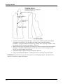
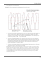
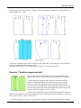
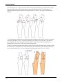
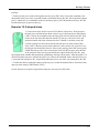
We are going to use the CUT and JOIN functions to make this sloper 2 inches shorter. First we will draw
a horizontal cut line, then we will cut the sloper in two. We will move the bottom piece up 2 inches, then
we will join the two pieces back together.
DRAW A LINE
Select the Line icon. It has a diagonal line on it.
[Select Line function]
Select the first point of the line with the mouse. It should be a bit to the left of the sloper object, and
slightly above the line that marks the waistline.
[Enter a point]
Now, as you move the mouse, the line will follow it around. We want to draw a perfectly horizontal line,
but you may notice that it's hard to keep it from being not quite level. This is where snap points come in.
SNAP TO ORTHO
Hold the Ctrl key down while pressing the F5 key.
<CTRL>+<F5>
This is the Snap to Ortho command. Note that you can interrupt other commands with the Snap
functions, just like the zoom and pan commands you learned earlier. You use Snap to Ortho to select a
point that is aligned vertically or horizontally with the last point you selected.
Move the mouse until the line following the mouse cursor is almost horizontal. A yellow X will appear.
If you look closely, the line following the mouse actually goes to the yellow X, not to the mouse cursor.
This is the snap point.
24
Tutorial 5: CUT, JOIN, and Snap Points
Now move the mouse up until the line following the mouse is a diagonal at approximately a 45 degree
angle. The yellow X disappears. This is because there is no ortho snap point close to the mouse.
Therefore, the line follows the mouse again.
Move the mouse until the line following the cursor is vertical. Once again you will see a snap point.
Snap to Ortho gives you both vertical and horizontal snaps.
Select a point to the right of the sloper object. Make sure the yellow X is showing when you click the
mouse, so the line you draw is a perfect horizontal. Make sure the line you draw is long enough to cut
the sloper in half.
[Select horizontal snap point]
You have now drawn a horizontal line that we will use to cut the sloper. Think of it as a scissor line.
You can use any polygon object (including lines, rectangles, and circles) to cut any other polygon object,
open or closed. Our line extends beyond the edges of the object it will cut in order to make sure of a
clean cut.
Now that we're done with our horizontal line, we don't want the snap point interfering with whatever we
do next. To get out of snap mode, hold down the Ctrl key and press the F1 key.
<CTRL>+<F1>
CUTTING AN OBJECT
Select the Cut icon. It looks like a pair of scissors.
[Select Cut function]
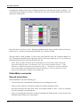
A prompt will ask you to select the object to be cut. Select the sloper object by putting the mouse cursor
on it and clicking the left button. Then click the right button or press <ESC>.
[Select sloper object]
<ESC>
Now a prompt will ask you to select the object to cut with. Select the line you just drew.
[Select horizontal line]
<ESC>
The prompt line should say:
Command:CUT
Select the object to be cut: *Polygon selected*
Select the object to cut with: *Polygon selected*
25
Tutorial 5: CUT, JOIN, and Snap Points
The computer now uses the line to cut the sloper. You won't see any difference yet, because the pieces
are still in the same places.
Let's get rid of the cut line you just drew, since we don't need it any more. Select the ERASE command
from the Edit menu. You learned how to use the Edit commands in Tutorial 4, so go ahead and erase the
cut line.
[Select Edit-Erase]
[Erase horizontal cut line]
Now, to shorten the sloper, we want to move the lower piece up exactly two inches. It's hard to be that
precise with the mouse. We could do it by typing the coordinates we need, but using snap points is
faster.
First, select the MOVE command and select the bottom part of the sloper.
[Select Move command]
[Select lower sloper object]
Notice that only the rectangular piece highlights, instead of the whole sloper.
Since the line marking the waistline should stay the same distance above the hipline, we need to move it
too. Select this line, then press <ESC> to indicate that you are finished selecting.
[Select horizontal waist line]
<ESC>
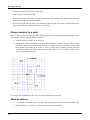
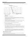
SNAP TO GRID
Press
<CTRL>+<F2>
to select Snap to Grid.
After you interrupt the MOVE command with the Snap to Grid command, the prompt window will
confirm the change, then repeat the last message:
Base point?:
Snap ON, Mode = GRID
Base point?:
The grid also appears. Remember that the grid points are exactly 1 inch apart. A yellow X will appear
anytime the mouse cursor is near a grid point. These snap points work much like the Snap to Ortho
points, except that a snap point appears at the nearest grid point. This will make it easy to select a base
and destination exactly 2 inches apart. Remember that it doesn't matter where the base point for your
Move is, as long as the destination is 2 inches above it:
[Select any grid point]
26
Tutorial 5: CUT, JOIN, and Snap Points
[Select grid point 2 inches above previous point]
Now the bottom piece of the sloper is moved up so it overlaps the top piece by 2 inches. We'd like to
recombine them.
JOINING TWO OBJECTS
Select the JOIN command from the Edit menu.
[Select Edit-Join]
This works very much like the CUT command. Select the top part of the sloper, then <ESC>, then select
the bottom part of the sloper, then <ESC>. Be careful not to select the waist line.
[Select top sloper object]
<ESC>
[Select bottom sloper object]
<ESC>
You have shortened your sloper by two inches. You have done it essentially the same way you would
have done with scissors, paper, and tape, but PatternMaker has made the process quicker and more
precise. Once you get used to the commands and snap modes, you will be able to move and rearrange
things very quickly.
You can experiment with the other snap modes. They will give you many ways to arrange and align
things perfectly. Remember that you can change from one snap mode to another in the middle of a
function, so you could (for instance) use the MOVE command to take a vertex of an object and put it on
a grid point by using both Snap to End Pt. and Snap to Grid. Here is the list of snap modes, which is also
on the plastic overlay:
Snap Off
No snap points
Snap to Grid
Nearest grid point
Snap to End Pt.
Nearest vertex of an object (use <F5> to view these)
Snap to Nearest
Nearest point on an object, whether or not it's a vertex
Snap to Ortho
Nearest point vertical or horizontal to previous point
Snap to Mid Point Nearest midpoint of a line segment
Snap to Intersect Nearest intersection of two line segments
Snap to Offset
Point offset from nearest point. Used for seam allowances and facings. This is a
little more complicated, so it's covered in a different tutorial.
Snap to Measured Point on an object, but a given distance from an existing point of the object. Used to
place
Distance
points at measured distances along curves such as armholes. This mode is also more
complicated.
27
Tutorial 5: CUT, JOIN, and Snap Points
Save the changes to your drawing.
[Select File-Save]
PLACING A POINT ON A CURVE (OPTIONAL)
The Snap to Measured Distance mode is a more specialized snap mode that is useful for placing points at
measured distances along curves. We will use it here to place an alignment mark on our piece’s armhole,
to be matched up against a similar mark on a sleeve piece.
Note: The Snap to Measured Distance mode is somewhat complicated, and it is an exception to the usual
way points are input in PatternMaker. Avoid confusion by exiting snap mode (<CTRL>+<F1>) as soon
as you are done using the snap mode.
We want the mark 3 inches from the point where the side seam meets the armhole. When drafting a
sleeve, we would put a similar mark on the sleeve cap, 3 inches from the corresponding corner. These
distances need to be measured along the curve, not in a straight line. Snap to Measured Distance
measures along an object, following curves and corners, instead of using the straight-line distance.
[Select Settings-Snap Mode]
[Select “MEASURED DISTANCE”]
[Click the “OK” button]
Now a dialog box appears, asking for
Snap Distance
Enter
3 <ENTER>
Now, select the Dot command.
[Select Draw-Dot]
Notice that the prompt to enter a point is different now.
Select reference point:
Move the mouse around the sloper object. Notice that a snap point appears when the mouse is close to
any vertex of the object. This is not the point you will enter; it is the start point that the three-inch
distance will be measured from. Remember:
In “Snap to Measured Distance” mode, you click the mouse twice to enter one point.
28
Tutorial 5: CUT, JOIN, and Snap Points
The point we want to measure from is the vertex where the arm hole meets the side seam.
[Select vertex at arm hole-side seam]
Now you see the usual prompt,
Enter a point, <ESC> to cancel:
When you move the mouse, there will be two snap points: one along the arm hole, and another along the
side seam from the reference point. In Snap to Measured Distance mode, the snap points always lie on
the same object that the reference point is part of.
Select the point on the arm hole. It is three inches from the reference vertex, measuring along the curve.
[Select snap point on arm hole]
To avoid confusion, take PatternMaker out of snap mode as soon as you are done using the snap mode.
<CTRL>+<F1>
You have now placed a dot at the point where the reference mark goes. Normally, you would put a
standard diamond or notch symbol here. Symbols are covered in a later tutorial, and you will find some
examples in the file LIBRARY.PAT. For the tutorials, you don’t need to save the alignment mark.
[Select File-Exit]
N
You now know how to use snap points to give your commands precise inputs. In the next tutorial, you
will learn some of the point editing functions, and we will use some more snap modes for these.
29
TUTORIAL 6: POINT EDIT FUNCTIONS
In this tutorial, you will use some of the commands from the Points menu to change the shape of your
sloper.
Start PatternMaker and open the file BACKSLOPER.PAT that you created in Tutorial 3 and modified in
Tutorial 5.
[Open file BACKSLOPER.PAT]
You should see the sloper object, the horizontal waist line you drew, and the box around them. If you
don't, press
<END>
to put them in view.
Remember that you drew these objects by entering the points, or vertices, that make them up. Let's use
the Points On/Off function to look at these again.
<F5>
A number of X's will appear all over the drawing. These are the locations of the vertices.
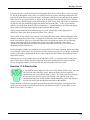
MOVE A VERTEX
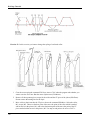
First, we are going to give the sloper a deeper neckline. Select the Points menu, then select the MOVE
VERTEX function.
[Select Points-move Vertex]
The prompt line will read:
Select point (w for selection window):
Selecting points is much like selecting objects. We want to move the point where the neckline meets the
center back line. This is at the upper left of the sloper, at coordinates (1,24.75). Put the mouse cursor on
this point and click the left mouse button.
[Select vertex at center back-neckline]
The X at this point changes from white to red. Now, much like with the MOVE function for objects, you
will be prompted to select more points until you press <ESC> or click the right mouse button. We only
want to move one point, so do this now.
30
Tutorial 6: Point Edit Functions
<ESC>
Now, just like the move function for objects, you need to select a base point and destination. Let's make
the neckline 3/4 inch deeper by moving this point from its present location at (1, 24.75) to the grid point
at (1, 24). Turn on Snap to End Pt.
<CTRL>+<F3>
and then select the same point you are moving. Make sure the X appears, indicating that you have a snap
point. Since this vertex is already marked with a colored X, the X indicating the snap point will not be
yellow, but it will be obvious when you have a snap point.
[Select vertex at center back-neckline]
Try moving the mouse around. You will see that the point you selected moves, while the rest of the
object stays still. Now, to put this point on the grid point (1,24), select Snap to Grid
<CTRL>+<F2>
and select the point with the mouse (refer to the mouse coordinates in the status bar to be sure it's the
right one).
[Select point (1,24)]
You could also have done this by typing (1,24) <ENTER>.
Get out of snap mode by pressing
<CTRL>+<F1>
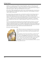
CHANGING THE SHAPE OF AN ARC
You will notice that you have just spoiled the curve of the neckline. You will also notice that there is an
X just to the right of the point you just moved, which doesn't seem to be connected to the drawing. This
is the corner point of the arc; it controls the shape of the arc. You can fix the neckline by moving this
point.
You can repeat the MOVE VERTEX command by clicking the left mouse button. Click on the arc
corner point to select it, then stop selecting points:
[Select arc corner point]
<ESC>
You now need to select a base point for your move. Adjusting the shape of arcs is best done by eye, so
don't worry about using snap points.
[Select any point]
31
Tutorial 6: Point Edit Functions
Now, when you move the mouse, the shape of the neckline changes. Move it until the neckline takes on
a reasonable shape.
When the neckline is right, the corner point should be level (horizontal) with the point you moved
previously. Since the corner point, the end point of the arc, and the point below that one form a right
angle, the neckline forms a square corner where it meets the center back line. This is important to
remember, so we will repeat:
The angle from the corner point, to the end of the arc, to the point after that, is the angle at which the end
of the arc meets the next line.
This also means that, to make an arc that is tangent (blends in smoothly) with the next line, the three
points should lie along a straight line.
When you are satisfied with the neckline, click the left mouse button.
[Select destination point]
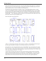
SELECTION WINDOWS
You may have wondered about the prompt you saw earlier that said:
Select point (w for selection window):
Selection windows are a way to make sure every vertex in a certain area is selected. This is especially
handy if there are a lot of vertices in a small area. For our example, you will use a selection window to
delete some unneeded points.
Look at the lower part of your sloper. Near the waistline, there are some X's marking vertices that were
created when you did the CUT and JOIN functions earlier. They don't hurt anything, but you can tidy up
the drawing a little by removing them.
Select the DELETE VERTEX command. This is the equivalent of the ERASE command for objects.
[Select Points-Delete Vertex]
Instead of clicking on some points to select them, type w (you don't need to press the <Enter> key).
W
The prompt line will now read:
Command: DELVERTEX:
Select point(s):
First point of selection window:
The selection window is a rectangle that is entered the same way you drew a rectangle in Tutorial 1.
Click with the mouse to enter one corner, move the mouse, then click again to enter the opposite corner.
The rectangle should contain all four of the extra points near the waist line.
32
Tutorial 6: Point Edit Functions
[Select corner of selection window]
[Select opposite corner of selection window]
The selection window will disappear and all of the points inside it will be highlighted. Be careful! You
may have selected some points you don't want to delete. Are the ends of the waist line highlighted? If
it's hard to tell, use
<F3>
to zoom in for a closer look.
If the ends of the line are highlighted, click the mouse on them to un-select them. When an X changes
back to white, that point is un-selected. Un-select any other points you didn't want to select, too.
[Un-select points with mouse]
(If you make a mistake too big to correct in this way, you can continue with the DELETE VERTEX
command, then use the UNDO command to put things back the way they were.)
When you have selected the correct points press
<ESC>
to delete them.
Save your work now. You are about to make some changes that you won't want to save. Before saving,
zoom to put the entire drawing in view.
<END>
[Select File-Save]
Experiment with the other commands in the Points menu. Read the appropriate manual sections for
details on how they work. Briefly, here is what they do:
Add Vertex
adds another vertex to an object. For example, you could change a triangle to a
rectangle.
Delete Vertex
removes one or more vertices
Move Vertex
moves one or more vertices
Rotate Vertex
rotates one or more vertices
Delete Segment
removes one line segment from an object. This will change a closed object to an
open object, and can cut an open object into two objects.
Corner Vertex
converts one or more arcs to straight lines and corners
Round Vertex
converts one or more straight lines and corners to arcs
33
Tutorial 6: Point Edit Functions
Align-X
aligns two or more points in the X (horizontal) direction. The first point you select
is the reference point; the other points will be moved to align with it.
Align-Y
aligns two or more points in the Y (vertical) direction.
Set/Measure Dist. measures the distance along a curve or section of an object. If you type in a new
distance, the curve or section will be adjusted to the length you enter.
When you are done experimenting, you are done with this tutorial. Exit PatternMaker and don't save
your latest changes.
[Select File-Exit]
N
34
TUTORIAL 7: POLYGONS, TEXT AND DIMENSION
OBJECTS WITH COLORS AND FILL PATTERNS
You have created open and closed polygons, lines, and rectangles in the previous tutorials. All of these
are really special cases of polygons – a line is a polygon with only two points, and so on. After you
finish drawing it, PatternMaker treats a line or rectangle just the same as any other polygon.
There are other object types that don't follow all of the same rules as polygons. For instance, you can't
add or delete vertices from them. These are text, dimensions, and symbol insertions.
To complete your introduction to polygons, you need to try setting a color and fillstyle, and to draw a dot
and a circle. Start PatternMaker, but don't load the drawing you have been working on. Instead, select
the Color icon. It's the one with swatches of various colors on it.
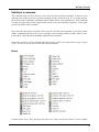
SETTING THE DRAWING COLOR
[Select Color icon]
A box appears with swatches of 16 colors. The swatch in the upper left can be any color; it represents
Uselayercolor, which will be explained later. Use the mouse to select one of the shades of blue.
[Select Blue square with mouse]
The word "Blue", or some variation, appears on the left side of the status bar at the top of the screen.
This is the current draw color. Everything you draw will be blue until you change this again.
SETTING THE FILL PATTERN
Now select the Pattern icon. It's next to the Color icon and has several diagonal bars on it.
[Select Pattern icon]
Another box appears, with samples of various styles of fill patterns. The all black box represents no fill
at all, which is what you will use most of the time. For now, select one of the other fill patterns.
[Select a fill pattern]
Now, draw a circle. The Circle icon is a circle.
[Select Circle icon]
To draw a circle, you first choose where its center should go. Select any point in the drawing area.
35
Tutorial 7: Polygons, Text and Dimension Objects
[Select any point]
Now move the mouse. A circle will follow it. When you have a circle you like, click the left mouse
button again.
[Select point on circle]
The circle is blue and is filled with the fill pattern you chose. Now, show the vertices.
<F5>
The circle is a closed polygon with eight points making up four arcs. You can change it with any of the
editing functions you have already learned.
Draw a dot. Put it anywhere in the drawing area, except inside the circle (you couldn't see it there).
[Select Draw-Dot]
[Select any point]
A dot is a polygon with one point.
Now, you can add some other object types to your sloper drawing. Open the file BACKSLOPER.PAT.
When PatternMaker asks if you want to save your current drawing, reply "no."
[Select File-Open]
[Select "NO" button]
[Select file BACKSLOPER.PAT]
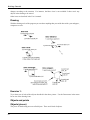
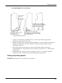
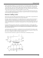
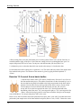
CREATING A DIMENSION LINE
Dimension lines are commonly used in engineering drawings to show the distance between two points.
In PatternMaker, you can use them to check the measurements of your drawings. In this example, you
will double-check the center back length of your sloper. Select the Dim icon. It looks like a pair of
arrows with two parallel lines.
[Select Dim icon]
A dimension line object has three points. The first two are the points at which the measurement is taken.
The third tells PatternMaker where to place the numbers. Your first prompt is
First point:
To make sure you enter the points exactly, select Snap to Endpoint.
<CTRL>+<F3>
36
Tutorial 7: Polygons, Text and Dimension Objects
Move the mouse to the point where the left (center back) edge of the sloper meets the curve of the
neckline. When a yellow X lights up at this point, click the left mouse button.
[Select point at Center Back-Neckline]
The next prompt is
Second point, <ESC> to cancel:
Move the mouse around. An arrow will follow the mouse cursor, connecting it with the first point you
entered. Select the point at the lower left corner of the sloper (again, make sure the yellow X lights up).
[Select point at Center Back-Hipline]
Now, as you move the mouse some more, you will see a double arrow, two parallel lines, and a small
dotted silhouette showing where the numbers will be displayed when you complete the dimension line.
The prompt line says:
Location for label:
Move the mouse until this silhouette is in a convenient clear area. Then click the left mouse button.
[Select point to locate label]
The dimension line object will now be drawn in its final form. It's blue because you set the drawing color
to blue in the first part of this tutorial. The two parallel lines indicate the points at which the
measurement is taken. The numbers should read
1' 9"
or
21.000"
If the numbers are too small to read, use the DIM SETTINGS command to change their size.
[Select Settings-Set Defaults-Dim]
A dialog box opens, with three fields: Text Size, Line Offset, and Arrow Size. Click in the field labeled
“Text Size” and type
1.5 <ENTER>
The numbers will be redrawn in the new size. If you ever run a command, such as MOVE VERTEX,
that changes the length of a dimension line, the numbers will automatically update to show the new
measurement.
If you wish, experiement with different numbers in the other fields, to see what effect they have on the
dimension line. Arrow Size and Line Offset are not covered in this tutorial.
37
Tutorial 7: Polygons, Text and Dimension Objects
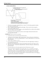
CREATING TEXT
Select the text icon. It looks like a large letter "A" in fancy script.
[Select Text icon]
A text object has only one vertex; it shows where the lower left corner of the text goes. Your first text
object will be a label for the sloper object, so select a point about 1 - 1/2 inches below the lower left
corner of the sloper.
[Select any point below lower left of sloper]
A box will come up, titled
Enter text info
Leave the size and angle alone. For "Text," enter
Back Sloper <ENTER>
The text will be added to the drawing.
To add another text object, select a point about halfway up the center back line (the left side of the sloper
object) and about 1 inch to the right of the center back line. The TEXT command will repeat
automatically when you do this.
[Select a point to right of center back line]
The text for this object (don't press <ENTER> yet) is
Center Back
Press
<TAB>
to move to the second text field, which is for setting the size of the text. The setting now is for 1-inchtall letters. To make them a bit smaller, enter
0.5 <TAB>
The last entry in this box is for the text angle. In PatternMaker, text can be drawn at any angle. 0
degrees means horizontal text. The angles are measured up (counterclockwise) from horizontal, so 90
degrees means the text is vertical, reading upwards. Type this in and then press <ENTER> to create the
text object.
90 <ENTER>
38
Tutorial 7: Polygons, Text and Dimension Objects
The words
Center Back
appear along the center back line. If the placement is bad, you can use the MOVE command to move the
text object.
Note: When selecting text and dimension line objects for MOVE and other commands, you have to click
the mouse near a vertex, not just anywhere on the object. Show the vertices (<F5>) if you aren't sure
where the vertices are.
You have now been introduced to closed and open polygons, dimension lines and text. PatternMaker has
one other type of object: the symbol insertion. These will be covered in Tutorial 10.
Save your work.
[Select File-Exit]
[Select "Yes" button]
39
TUTORIAL 8: INTRODUCTION TO GRADING – THE
RECTANGLE
Note: This tutorial applies to the Expert and Marker Versions only.
In this tutorial you will create your own grading rule. You will save a grading table, and you will use it
to apply the same grading rule to another object. Then you will use the grading information to create a
nest of different sized pieces. For simplicity, you will start out by grading a rectangle, but the procedures
you learn will apply to any pattern piece.
Start PatternMaker. If you have it running already, use the NEW command to start a new drawing. Use
the RECT command to draw a rectangle.
[Select Rect command]
[Enter a rectangle]
CREATING A GRADING RULE
Select the ADD ARROW command from the Grade menu.
[Select Grade-Add Arrow]
The first prompt will ask you
Point to attach arrow to:
Select the vertex at the lower right corner of the rectangle.
[Select lower right corner of rectangle]
<ESC>
The next prompt is
Select end point for arrow:
Select any point you like. The end of an arrow doesn't have to be a vertex of an object. In a minute, you
will use the EDIT ARROW command to set this more carefully.
[Select any point]
<ESC>
Now, repeat the ADD ARROW command and add an arrow to the upper left corner.
40
Tutorial 8: Introduction to Grading
[Select upper left corner of rectangle]
<ESC>
[Select any point]
<ESC>
Go to the Grade menu and select the ADD TACK command. A tack is just an arrow with a length of 0.
Add the tack to the lower left corner of the rectangle.
[Select Grade-add Tack]
[Select lower left corner of rectangle]
Now, three of the four corners of the rectangle have grading information attached (including the tack).
Use the EDIT ARROW command to make this information more complete.
[Select Grade-Edit Arrow]
The prompt will ask you to select an arrow. You do this by clicking on the vertex that the arrow is
attached to (the base of the arrow). Start with the lower right corner.
[Select lower right corner of rectangle]
<ESC>
A box will appear, titled
Enter Arrow Info
The box will have three white bars, or edit fields, labelled
Name:
dx=
dy=
You can type information into these edit fields. They work much like most word-processing programs:
whatever you type will be entered in whichever edit field is highlighted. Currently, the name "ARROW"
is highlighted.
You need to give this arrow a name that will describe where it is placed. Call it "Lower Right." Use the
<TAB> key to move to the next edit field.
Lower Right <TAB>
Now the middle field is highlighted.
The fields "dx=" and "dy=" represent the distance the point will move in the x and y directions,
respectively, when you grade this object to the next larger size. Set the values to 0.5 and 0.
41
Tutorial 8: Introduction to Grading
0.5 <TAB>
0
The edit fields should now say,
Name:
Lower Right
dx=
0.5
dy=
0.
Enter this information by clicking on the "Ok" button at the bottom of the box, or by pressing <ENTER>.
[Select Ok button]
The arrow at the lower right should now be very small and point to the right. Press
<F7>
to see the arrow's name.
Now, edit the arrow at upper left and the tack at lower left. Remember, you can repeat the EDIT
ARROW command by simply clicking the mouse on the next point whose arrow you want to edit. Give
them the following names and values:
[Select upper left corner]
<ESC>
Upper Left <TAB>
0. <TAB>
1.0
[Select Ok button]
[Select lower left corner]
Lower Left
[Select Ok button]
The dx and dy values for the tack are left unchanged.
CREATE A GRADING TABLE
Select the SAVE TABLE function:
[Select Grade-Save table]
42
Tutorial 8: Introduction to Grading
and the prompt will read
Select objects containing grading information:
Select object, ? for help, <ESC>=done:
In this case, all the grading information you want to save is attached to a single object, so just select the
rectangle and then press <ESC> to stop selecting.
[Select rectangle]
<ESC>
Now you are asked,
Select file to save grading table in:
The box that appears works exactly the same as the boxes used for selecting drawing files, except that a
grading table file's name ends with ".GRD". Call this file "SIMPLE.GRD".
SIMPLE <ENTER>
Another box, with an edit field, will appear, titled "Description of Grading Table". Give your table the
title "Simple grading rule."
Simple grading rule <ENTER>
You have created a grading rule that can now be applied to any pattern. (Normally, or course, you would
create your grading information on a real pattern instead of a rectangle.)
To apply this grading rule to your sloper, first open the sloper drawing you have been working on in the
other tutorials.
[Select File-Open]
[Select file BACKSLOPER.PAT]
Then select the READ TABLE command from the Grading menu.
[Select Grade-Read table]
From the list of grading table files, select the one you just created.
[Select file SIMPLE.GRD]
The prompt line will remind you of the description you gave when you saved the grading table, and then
start asking you where each arrow should go. Notice that it uses the names you gave the arrows earlier.
Grading using Simple grading rule
43
Tutorial 8: Introduction to Grading
Select point for Lower Right, or <ESC> to ignore:
IMPORTANT: Pay attention to the names of the arrows! The sloper object is a very different shape
than the rectangle was, and the arrows may not be listed in the order in which you created them. This is
why it is important to give your arrows good, descriptive names. If the arrows are listed in a different
order than in the following description, be sure to put them in the right places.
To place an arrow, simply use the mouse to select the point it should be attached to. If you press <ESC>,
PatternMaker will ignore an arrow and move on to the next one, but for this tutorial, use all three of the
arrows in the table.
[Lower Right: select lower right corner of sloper object]
[Upper Left: select point where neck hole meets center back line]
[Lower Left: select lower left corner of sloper object]
The Upper Left arrow (the one that points up) should be near the upper left of the sloper object, at the
bottom left point of the curve that represents the neck hole.
GRADING A PATTERN
First, erase the rectangle that surrounds your sloper, because the larger sizes you create will be drawn
over it.
[Select Edit-Erase]
[Select large rectangle]
<ESC>
Now, select the GRADE command. You will only be grading one object – the sloper object.
[Select Grade-Grade]
[Select sloper object]
<ESC>
A dialog box will appear, asking you for several pieces of information:
Grading info
Number of sizes to generate:
1.0000
Size interval (negative for smaller sizes) 1.0000
For the number of sizes, enter "3". Leave the size interval at 1. Don't press <ENTER> yet.
3
44
Tutorial 8: Introduction to Grading
The 3 means you will be creating 3 new sloper objects. The size interval of 1 means that, since the
original sloper is a size 12, the new ones will be sizes 13, 14, and 15. If you had entered 2 for the size
interval, the new objects would be sizes 14, 16, and 18. If you had entered -2, they would be sizes 10, 8,
and 6. The grading arrows tell PatternMaker what the difference between one size and the next is.
Note: Recall that you have shortened the sloper from its original size 12 and that your grading rule was
designed for simplicity, not realism. Therefore, your sizes "13, 14, and 15" don't correspond to real
clothing sizes.
Okay, now you can finish the grading command.
[Select "OK" button]
PatternMaker creates three new slopers: a green one, a blue one, and a red one. Look carefully at the
arrows to see how PatternMaker calculated where each point belonged:
•
The point with the tack didn't change from one size to the next.
•
At each point with an arrow, the corresponding point of the green object is at the end (head) of the
arrow.
•
At each point without an arrow, PatternMaker uses the nearest two arrows to determine where the
point should go.
The change from the green sloper to the blue sloper is the same as the change from the white one to the
green one, and so on.
You have finished your introduction to PatternMaker's grading system. As you can see, once you have
created the arrows that define your grading rule, it's very easy and quick to make new sizes.
A hint on creating arrows: there are two good ways to put together a grading rule. One is to use the
EDIT ARROW command to enter predetermined dx and dy values, as you did in this tutorial. The other
is to draw two copies of an object, one a size larger than the other. Then draw arrows to connect points
on the smaller object with the corresponding points on the larger object. Use Snap to End Point
(<CTRL>+<F3>) to make the arrows exact.
Save your work for the next tutorial.
[Select File-Save]
In the next tutorial, you will learn about Layers, and you will find out why the slopers that the GRADE
command created are different colors.
45
TUTORIAL 9: LAYERS
Layers are a very useful feature of PatternMaker that let you hide some parts of your drawing when you
don't want to see them, and show them when you do. You will normally put each different size in your
pattern on a different layer, and turn off the layers for all sizes except the one you are working with.
Start PatternMaker and open the drawing file you just graded in the last tutorial.
[Select File-Open]
[Select BACKSLOPER.PAT]
Every object in PatternMaker has a layer number. The first sloper you drew – the white one – is on layer
#0 because this is the default layer when you start PatternMaker. The GRADE command puts the new
objects it creates on new layers, so the colored slopers are on layers 1, 2, and 3, respectively.
Every object in PatternMaker also has a color number. The white sloper is drawn in color #0 because
this is the default drawing color. Color #0 is not white, but "Uselayercolor." This means that the object
is drawn in whatever color is the default color for that object's layer. This color coding makes it easy to
see which objects belong together. White is the default color for layer #0, green is the default color for
layer #1, and so on. This is why the other slopers are different colors. If an object is any color other than
"Uselayercolor," it will be drawn in that color regardless of what layer it is on.
Look at the status bar at the top of the screen. On the left is a box saying
USELAYERCOLOR
This box tells you what color you are currently drawing in.
In the middle of the status bar is a box saying
Layer0
This box tells you what layer you are currently drawing on. The number of the layer is 0 and the name of
the layer is "Layer0" You can change the name of a layer with the Layer command, but its number
always stays the same.
This box is also an icon! Put the mouse cursor on the words "Layer0" and click the left button to select
the LAYER command.
[Select Layer box from status bar]
A box appears, titled
Set/Edit Layers
CURRENT
NAME
COLOR
ON
Below is a table listing the information for all the layers that are availble in PatternMaker. Each part of
this field is also an icon.
46
Tutorial 9: Layers
CHANGING THE CURRENT LAYER
The line for the current layer is marked with an asterisk under the word "CURRENT." The current layer
is layer #0. To change the current layer to layer #2, place the mouse cursor in the area to the left of the 2
and under the word "CURRENT." Click the left button.
[Select Layer #2 under CURRENT]
Now the line containing the words "Layer2" should be highlighted. Also, the asterisk in the left part of
the box moves to this line. The prompt line will read
Currentlayer set to (2) Layer2
If you selected the wrong layer by mistake, try again.
CHANGING A LAYER NAME
Now put the mouse cursor on the word "Layer2" and click the left button.
[Select "Layer2" under NAME]
Delete “Layer2” and type in a new name. For this tutorial, call it “Size14,” since the blue sloper you
created in the last tutorial represented a size 14 (it’s not a true size 14, remember).
Size14 <ENTER>
You can rename the other layers if you like, but it isn't a necessary part of this tutorial.
CHANGING A LAYER'S DEFAULT COLOR
You will rarely do this, but it gives a good illustration of layer default colors. Under the header
"COLOR" in the Layer box, on the layer you just renamed, is a light blue (actually, cyan) square. To
change Layer 2's color to yellow, put the mouse on the square and click the left mouse button.
[Select cyan square under COLOR]
A small box will appear in front of the layer box, with sample squares for 16 colors. Notice that the
square at the upper left of the color grid is cyan, the original color of this layer. The color of this first
square will always represent the default color of the layer you are dealing with at the time. The rest of
the colors are your remaining color choices. Selecting black is generally not recommended, as your
drawings would be invisible. Select the yellow one by clicking the mouse on it, then click the “OK”
button.
47
Tutorial 9: Layers
[Select yellow square in COLOR box]
[Click the “OK” button]
You will return to the Set/Edit Layers dialog box. The square that used to be cyan is now yellow.
TURNING LAYERS ON AND OFF
This is by far the most important function of the LAYER command. Right now all the layers are turned
on. You can turn any layer off by clicking the mouse on the word "ON." You can turn a layer on again
by clicking on the word OFF. To make everything except the size 14 sloper disappear, turn off layers #0,
#1, and #3.
[Toggle layer 0 to OFF]
[Toggle layer 1 to OFF]
[Toggle layer 3 to OFF]
Click "OK" button to close the dialog box and return to the drawing screen.
[Select "OK" button]
The picture is redrawn. The only object that appears is the size 14 sloper. Its color has changed from
cyan to yellow. In the status bar, the message
Layer0
has changed to
Size14
Anything you draw now will be on Layer 2 (since that’s the one you marked with the asterisk), and if you
don't use the COLOR command to give new objects a color, they will be drawn in yellow.
The objects in the layers you turned off still exist, but you can't see them. You also can't select them for
any editing functions, you can't print them, and none of the snap modes will snap to any of them. The
Layer command is a quick and easy way to temporarily hide things that you will want to show again
soon.
RESETTING THE LAYERS
Select the LAYER command again.
[Select Layer box from status bar]
Select the button on the right titled "Reset". When a box with a question appears to confirm your choice,
answer "yes." Select the "OK" button in the Layer box.
48
Tutorial 9: Layers
[Select "Reset" button]
[Select "Yes" button]
[Select "OK" button]
You have changed the names and colors of all the layers back to their original values, and turned them all
back on. Your drawing should now appear just like it did when you started this tutorial.
You don't need to save your work for the next tutorial.
49
TUTORIAL 10: SYMBOLS AND LIBRARY FILES
A library is a file containing commonly used drawing items that you can read into other drawing files.
You can read objects, symbols, and groups from a library file.
A symbol is a detail of a drawing, such as a buttonhole, pleat, or drawing label, that is repeated in many
places. By using symbol libraries, you can transfer commonly used symbols from drawing to drawing
and ensure that every copy of a given symbol is identical. In this tutorial you will see how to use one of
the symbols that are supplied in PatternMaker's symbol library. You will also see how to create your
own symbols, change an existing symbol, and make your own symbol libraries.
The difference between a symbol and a group is that every instance of a symbol in a drawing is the same,
but if you load several different copies of a group into your drawing, you can change or edit some copies
without changing the others. Use groups in your libraries if you want to load a group of objects and then
modify them, for instance to put a standard sleeve into all your patterns.
If you aren’t clear how the difference affects your work, use whichever you like.
Start PatternMaker and draw a rectangle. This will be a simple representation of a shirt front on which
you will place some buttonhole symbols.
[Select Rect command]
2,2 <ENTER>
5,12 <ENTER>
SELECTING A SYMBOL LIBRARY
From the Symbols menu, choose the Library command.
[Select Symbols-liBrary]
A file selection box will appear. This box looks exactly like the selection box for drawing files. This is
because every drawing file can be used as a symbol library, and vice versa.
Select the file LIBRARY.PAT
[Select file LIBRARY.PAT]
On the prompt line you will see the response
Reading file C:\PATTERN\LIBRARY.PAT 11 symbols scanned
This verifies that the file is OK and counts the number of symbols it contains.
50
Tutorial 10: Symbols and Library Files
LOADING A SYMBOL
Now that you have selected a library file, you can load one or more symbols from it. Select the LOAD
SYMBOL command from the Load from Library submenu.
[Select Symbols-Load From Library-Symbol]
A list of symbol names appears. Select the symbol called BTNHOLE.
[Select BTNHOLE from symbol list]
The prompt line says,
Library: C:\PATTERN\LIBRARY.PAT
Symbol loaded successfully
Command:
The symbol is now loaded, but your drawing doesn't look any different. This is because there are two
steps to using a symbol. The first step is to define the symbol in the computer's memory; this is what you
have just done. Now, you need to place one or more insertions of the symbol into the drawing. To do
this, you need to run the INSERT command.
[Select Symbols-Insert]
A list box appears. The only name in the list is BTNHOLE, because this is the only symbol defined.
Select it and click on the "OK" button.
[Select BTNHOLE]
The prompt line will read
Insertion point:
Inserting a symbol is similar to placing an object with the MOVE command. For this example, place the
buttonhole one inch from the left edge of the rectangle, using Snap to Grid:
<CTRL>+<F2>
[Select grid point (3,3)]
If you repeat the Insert command by clicking the mouse on the drawing area, you can place more copies
of the same symbol.
[Click left mouse button in drawing area]
[Select grid point (3,3)]
[Click left mouse button in drawing area]
51
Tutorial 10: Symbols and Library Files
[Select grid point (3,5)]
[Click left mouse button in drawing area]
[Select grid point (3,7)]
[Click left mouse button in drawing area]
[Select grid point (3,9)]
[Click left mouse button in drawing area]
[Select grid point (3,11)]
You should now have five buttonholes along the left edge of your rectangle. If they are too small to see,
use <F3> to zoom in on them. Then use <END> to view the whole drawing again.
<F3>
<F3>
<END>
Display the vertices.
<F5>
Note that each insertion has only one vertex. The X's for these are slightly larger than the X's for
ordinary objects. They are located at the insertion points.
CREATING OR REDEFINING A SYMBOL (Expert or Marker Versions only)
You can create your own symbols from objects already in your drawing. You can redefine an existing
symbol by creating a new symbol with the same name. The following procedure will redefine
BTNHOLE as a small square and the words "Buttonhole goes here." In a real pattern layout, you might
use this feature to change the style or size of a buttonhole.
First, zoom in on the origin (point (0,0) – just below and left of the rectangle) so you can see what you
are doing. Zoom until 8-10 grid dots cover the width of the screen.
<Leftarrow>
<Downarrow>
<F3>
<F3>
Draw a 1/2-inch square, centered on the point (0,0). Draw a text label, too.
[Select Rect function]
[Select point (-.25, -.25)]
[Select point (.25, .25)]
52
Tutorial 10: Symbols and Library Files
[Select Text function]
[Select point (0.5, 0)]
Buttonhole goes here <TAB>
0.5 <ENTER>
Now you are going to use these two objects to define a symbol. From the Symbols menu, select Create.
[Select Symbols-Create]
A box appears. On the left, the name
BTNHOLE
is the only existing symbol. On the right,
SYM1
is the default name – the name that will be assigned to your symbol if you just press <ENTER>. Since
you want to redefine BTNHOLE, select that name.
[Select BTNHOLE from list]
<ENTER>
Another box will ask you if you want to redefine symbol BTNHOLE. Answer yes.
Y
Now, you need to slect a group of objects that will be included in the symbol definition. Select the
square and the text you just drew. Remember that to select a text object, you need to click at its lower
left corner.
[Select small square]
[Select text]
<ESC>
The next prompt is
Insertion point:
The insertion point is the "handle" that you use to place a symbol. It's important to keep the same
insertion point when redefining a symbol; otherwise all the symbol insertions will be moved off-kilter.
This is why you centered the square around (0,0): the existing BTNHOLE has its insertion point at its
center. Select the origin.
[Select point (0,0)]
53
Tutorial 10: Symbols and Library Files
All the insertions of BTNHOLE are now changed to reflect the redefined symbol. A symbol can also be
redefined by loading a symbol of the same name from a library file.
[Select Erase function]
[Select small square at origin]
[Select text near origin]
<ESC>
Changing or erasing the original objects doesn't affect a symbol definition.
CREATING A SYMBOL LIBRARY
To create a symbol library, simply save a drawing that has the desired symbols defined. Any ordinary
drawing file that has one or more symbols defined can be read as a symbol library. This is so simple that
it won't be covered in this tutorial.
Note: Even though you can't see it, a symbol definition is part of a drawing. This means that it is saved
when you save a drawing to a file, and when you open a new drawing the previous symbol definitions are
not part of the drawing.
THE EXPLODE COMMAND
The EXPLODE command can do two things: it will replace a symbol insertion with a group of objects
(without changing the symbol definition) or it will replace a polygon object with a group of line
segments. In both cases, the result looks the same as the original, but you can work with the individual
parts separately.
[Select Symbols-Explode]
[Select large rectangle]
[Select any symbol insertion]
<ESC>
[Select Move command]
[Select left edge of large rectangle]
[Select square from just-exploded insertion]
<ESC>
[Select any base point]
[Move mouse]
You will see the pieces of the exploded items move, while the remainders stay put. This verifies that
they really were broken up. You don't need to finish the MOVE command.
54
Tutorial 10: Symbols and Library Files
<ESC>
The PURGE UNUSED command deletes all unused symbol definitions from memory. It will not be
covered in this tutorial.
We have not covered the LOAD OBJECT and LOAD GROUP commands. They work much like the
LOAD SYMBOL command, except that you place the object or group directly in the drawing instead of
making insertions. Any PatternMaker file can be an object or group library, but you can only load
objects and groups that you have given a name to (see NAME OBJECT and NAME GROUP in the
User's Manual).
You are now done with this tutorial. Don't save your work.
[Select File-Exit]
N
55
TUTORIAL 11: OFFSETS, SEAM ALLOWANCES, AND
FACINGS
To make seam allowances and facings, you will want to follow the outlines of existing objects,
but offset them by some distance. You can do this with the OFFSET command, the SEAM
ALLOWANCE command, or the Snap to Offset feature.
Start PatternMaker and open the drawing file you have been working on. If the new sizes you
graded are visible, turn them off.
[Select File-Open]
[Select BACKSLOPER.PAT]
[Select Layers command]
[Turn Layers 1, 2, 3 OFF]
[Select “OK” button]
VARIABLE SEAM ALLOWANCE
Use SEAM ALLOWANCE to add a seam allowance to a pattern piece. You can change the
width of the seam allowance at different points. For instance, collars usually have less seam
allowance than side seams.
[Select Draw-Seam Allowance]
Now select two points on the object. These points are the ends of a section that will have a seam
allowance added to it.
[Select point where side seam meets waist on sloper object]
<ESC>
[Select point where side seam meets arm scye]
<ESC>
You have selected the two ends of the side seam. PatternMaker doesn’t know whether you want
to connect these points the long way or the short way, so it highlights the section in red and asks,
Is this the right segment?
Answer Yes or No until PatternMaker has selected the correct section.
A box will appear, asking you for offset distance (the width of the seam allowance). The default
is 1/4 inch (.25). Change this to 1/2 inch.
.5
56
Tutorial 11: Offsets, Seam Allowances, and Facings
[Select “OK” button]
Now the program asks you to select another point on the object.
[Select point where arm scye meets shoulder]
<ESC>
Another box appears, asking you for offset distance. The seam width for this curved section
along the armscye is 1/4 inch.
.25
Before you select “OK,” look at all four of the buttons in this dialog box. The Cancel button
cancels the whole operation. The Done (Open) button ends the seam allowance right where it is
and makes the new seam allowance object an open object. The Done (Closed) button continues
the seam allowance all the way around to where it started, making a closed object. This is the
usual way to finish a seam allowance.
[Select “OK” button]
Finish the seam allowance on your own.
[Select more sections and enter seam widths]
[Select “Done (Closed)” when finished]
NOTE: FIXED-WIDTH SEAM ALLOWANCE
The OFFSET command is a quick and simple way to draw a seam allowance that is the same
width all the way around an object. It works very similarly to the SEAM ALLOWANCE
command, except that there is only one dialog box in which to enter a measurement.
CHANGE THE LINE STYLE
Wouldn’t it be better if the seam allowance was drawn with dashed lines? Select the CHANGE
OBJECT command. Choose the seam allowance object you just created and press <ESC>. You
will be asked to choose an attribute to change; select “Line Type.” When the list of line types
appears, select one of the dashed styles.
[Select Change Object command]
[Select seam allowance object]
[Select LINETYPE]
[Select dashed line type]
57
Tutorial 11: Offsets, Seam Allowances, and Facings
SNAP TO OFFSET
Because the seam allowance object may cause confusion in the following procedure, you should
erase it now. Each point of an existing object creates offset snap points, so until you are used to
Snap to Offset, it’s best not to have any extra objects around.
Zoom in on the neck line, until 8-10 grid points fill the width of the screen.
[Select Erase command]
[Erase seam allowance object]
[Zoom in on neckline]
Now you will draw a 1-inch facing to go on the neckline. Select blue as your drawing color (this
is so you can see the new object clearly).
[Select Color command]
[Select blue]
Select the POLY function.
[Select POLY command]
The first point of the facing goes 1 inch from the neckline, on the shoulder line. Therefore, the
offsets are 1 and 0. Use <CTRL>+<F8> to select Snap to Offset mode and enter these values.
(It doesn’t matter which order you enter them).
<CTRL>+<F8>
1 <TAB>
0 <ENTER>
Move the mouse around. You will see the yellow snap cursor light up occasionally. When it
does, it’s at a point that is displaced from a vertex by 1 inch (measured from the line connecting
the point with the next point) and 0 inches (measured from the other line going into the vertex).
Each vertex can generate up to four snap points, so you have to use your judgement to find the
right one.
The point you want lies on the shoulder line (because its offset is 0 inches) and is one inch from
the vertex where the shoulder line meets the neckline. Use the grid (<F4>) to see how much is
one inch.
[Select snap point on shoulder line]
This point is the start of an arc that parallels the neckline, one inch away from it. Use the Point
Type Options box to select the Arc option.
<ESC>
[Select “Arc
58
X”]
Tutorial 11: Offsets, Seam Allowances, and Facings
The next point, the corner point, needs to be offset from the corner point of the neckline curve.
With one of your offset values being 0, the snap points would lie on the imaginary lines
connecting the corner point with the ends of the arc. This isn’t what you want. Change the
offset distances to 1 inch and 1 inch.
<CTRL>+<F8>
1 <TAB>
1 <ENTER>
Now find the snap point approximately an inch below and to the right of the corner point of the
neckline. Use <F5> to show the corner point, if you need to.
[Select snap point]
The point you entered is the corner point of the new arc. The end of the arc is 1 inch below the
point where the neckline meets the center back line. You need to reset the offset distances again.
<CTRL>+<F8>
0 <TAB>
1 <ENTER>
[Select snap point below center back-neck point]
You now have an arc that parallels the neckline, one inch below it. For the rest of the facing, use
Snap to end point to trace the neckline itself. Don’t forget to switch to Line in the Point Type
Options, and back to Arc.
<CTRL>+<F3>
<ESC>
[Select “Line
L”]
[Select center back-neck point]
<ESC>
[Select “Arc
X”]
[Select corner point of neckline arc]
[Select shoulder-neck point]
<ESC>
<ESC>
When you have finished drawing the facing object, it will look like this:
59
Tutorial 11: Offsets, Seam Allowances, and Facings
(The facing object is shown slightly misaligned here so you can see it better.)
A reminder on Snap to Offset: set both the offset distances the same if you want a constant
offset distance. Set two different values if you want to draw a point where two different offsets,
or two different widths of seam allowance, come together.
SINGLE SEAM ALLOWANCE
The SEAM ALLOWANCE command lets you add a seam allowance to a single segment or edge
of an object. We will use it here to create a yoke type bodice piece.
Do you remember the CUT command from Tutorial 5? Draw a line, more or less horizontal,
across the sloper object. It doesn’t matter exactly where it goes, but it should cut through at the
armhole. Make sure it is long enough to cut the sloper cleanly in half. Then use the CUT
command to cut the sloper in two.
[Select Line function]
[Draw line across sloper object]
[Select Cut function]
[Select sloper object]
<ESC>
[Select the line you just drew]
<ESC>
[Select Erase function]
[Select the line you just drew]
60
Tutorial 11: Offsets, Seam Allowances, and Facings
<ESC>
Now, move the two pieces of the sloper an inch or two apart.
[Select Move function]
[Move top half of sloper up 1-2 inches]
We need to add seam allowances to the two pieces so we can sew them back together. The
SEAM ALLOWANCE function is in the Draw menu.
[Select Draw-Seam Allowance]
Select the bottom edge of the top piece of the sloper – the edge created by the cut you just made.
The SEAM ALLOWANCE function doesn’t select objects or points; it selects a segment
connecting two points. Click the mouse on the bottom edge and it will highlight. If the wrong
segment highlights, click on the right one. Then press <ESC>.
[Select bottom segment of top sloper piece]
<ESC>
A seam allowance is added onto the object. The width is the same width that you set with the
OFFSET command. Notice that the ends of the seam allowance are not square; they are flared
slightly so that if you fold them back, they will match up with the rest of the piece.
Add a seam allowance to the corresponding edge of the other piece of the sloper.
[Select Draw-Seam Allowance]
[Select top segment of bottom sloper piece]
<ESC>
Save your work.
[Select File-Exit]
Y
If you have PatternMaker Home or Expert, you are now done with the tutorials. Start using
PatternMaker to make your own patterns, and keep reading the manual as you learn the system
better and better.
If you have PatternMaker Marker version, go on to the next tutorial to learn how to arrange and
print markers for production.
61
TUTORIAL 12: MARKERS
(Note: This tutorial applies to the Marker version only)
PatternMaker’s marker functions let you arrange pattern pieces to make production markers. The CUT
RATIO function prepares the pieces by making multiple copies of each one, each size according to its cut
ratio. To use material most efficiently, the ARRANGE MARKER function lets you move pieces next to
each other so they just touch. PatternMaker calculates the percentage of material used in the marker so
you can find the most efficient arrangement. The marker report lists other information, such as the cut
ratio and yardage requirements. The PRINT MARKER function prints the marker area and the pieces in
it. By printing to a file, you can create a marker that you can put on a diskette, send over a modem, and
print over and over from any computer, even one without PatternMaker installed.
In this tutorial, you will make a marker for a children’s T-shirt. A pattern has already been created for
you; it is in the file TUT12.PAT. Although it is very simple, this is a complete pattern, ready to grade
and mark.
[Select File-Open]
[Select file TUT12.PAT]
This file contains five pieces: a front, a back, two sleeves, and a collar. Note that the notch marks have
already been grouped with the sleeves and armscyes, and that the grading arrows have already been
added, setting the grading rule. This tutorial assumes that you won’t cut pieces on the fold.
Since the collar belongs to a different material group (ribbing), it will not be in the marker.
[Select Misc. - Settings - Layer]
[Turn layer “Ribbing” off]
SETTING THE CUT RATIO
Don’t exit the Layer command yet, because you also need to set the cut ratio. This marker will contain
enough pieces to make
1 size Small
3 size Medium
2 size Large
These numbers are the “cut ratios” listed in the Layer display.
Put the mouse on the number 1 in the row for size Medium, under the word “Ratio” and click the left
button. The 1 changes to a 2. Click again to make it a 3. If you make a mistake, you can use the right
button to reduce the cut ratio.
[Click left button on Medium cut ratio]
62
Tutorial 12: Markers
[Click left button again]
Similarly, set the Large cut ratio to 2.
[Set Large cut ratio to 2]
[Click Done button]
Now, you have hidden the collar piece and prepared the cut ratios for sizes Medium and Large, which
you will soon make. Before you grade the pattern, you need to define the marker pieces.
DEFINE MARKER PIECES
To define a drawing object as a marker piece, use the DEFINE PIECE function in the Marker menu.
[Select Marker-Define Piece]
Each of the four pieces needs to be made into a marker piece. The DEFINE PIECE function defines one
object at a time as a marker piece, so repeat the command for each piece:
[Select front piece]
<ESC>
[Select back piece]
<ESC>
[Select sleeve]
<ESC>
[Select other sleeve]
<ESC>
MARKER MODE
The objects still look the same, but they are now defined as marker pieces. In fact, they are the same;
you can do everything with them that you could before. To check for mistakes, switch the view mode to
Marker Mode. Do this by clicking the mouse on the words “Draw Mode” at the left of the status bar.
(These words don’t appear in the PatternMaker Home and Expert versions.)
[Select Marker Mode]
All the objects in the drawing disappear, except for the ones you just defined as marker pieces. You can
go back to Draw Mode any time by selecting the Marker Mode function again.
Switching to Marker Mode is much like turning layers off (see Tutorial 9). If any of the four pieces
disappear, this means you made a mistake while defining marker pieces. If so, click on the words
“Marker Mode” to return to Draw Mode, and correct your mistakes. When you are ready, continue.
63
Tutorial 12: Markers
SET MARKER AREA
[Select Marker-Set Marker Area]
When you select the Set Marker Area function, the first thing you see is a dialog box asking:
Width of Marker
For this demo, we assume your printer paper is 36 inches wide. Type
34 <ENTER>
36-inch printers usually have a 34-inch wide printing area, and leave an inch margin on each side. If you
choose to make your marker wider than your paper, your marker will be printed in more than one piece,
which you can tape together.
The marker area is a gray-and-red outline that represents the roll of material on the cutting table. Notice
that the marker area always extends off the screen to the right, no matter how far you zoom out. This is
because the marker can be any length, depending on how many pieces you put into it. Place it anywhere
in the drawing.
The prompt says,
Select location for marker area:
[Enter any point]
Now it’s time to grade the T-shirt. Since this isn’t a grading tutorial, we have already put in the grading
information for you (see Tutorial 8 for grading).
Two things to remember when you grade this pattern: first, the collar piece won’t be graded because its
layer is hidden. Second, the notch marks will be selected and graded, even though they are hidden,
because they are grouped together with the main pieces (this was also done for you beforehand).
Grade the pattern now, grading all of the objects in view and making two larger sizes.
[Select Grade-Grade]
[Select ALL icon]
<ESC>
Sizes:
2 <TAB>
Size interval: 1 <ENTER>
Now you have four nests.
64
Tutorial 12: Markers
MULTIPLY BY CUT RATIO
[Select Marker-Cut Ratio]
[Select All icon]
<ESC>
The CUT RATIO command makes copies of all the selected objects. The number of copies for each
layer is equal to the cut ratio you set earlier. PatternMaker now asks you,
Pre-place pieces?
PatternMaker is offering to spread out the pieces so that they will be easier to see and arrange. Answer
“Yes.”
Y
PatternMaker makes a total of 24 pieces and lays them out in rows above the marker area. Use Zoom All
to put everything in view again.
<END>
Note: Notice that all of the pieces you created with GRADE and CUT RATIO are visible in marker
mode. This is because a copy of a marker piece is also a marker piece.
Another note: If you do things in the order given above, you can be sure your marker has the right
number of pieces of each size. This isn’t a problem with a simple marker like this one, but in a
production environment, you may find yourself looking at a marker with over 100 pieces, which
somebody else has worked on, and not know if there are extra, missing or modified pieces. Use the
MARKER REPORT function (below) for a quick check. Here’s how to clean up a marker if you do have
a problem:
Erase all the pieces except the original set – one copy of each piece in the base size. Make sure the
grading arrows and cut ratios are the way you want them. Then, use the Grade and Cut Ratio commands
again. Now you know exactly what you have.
ARRANGING A MARKER
Now comes the part you’ve been waiting for – actually putting the marker together. PatternMaker does
not arrange the pieces automatically in the marker. This is because you can do the job much better than
the computer can. Select the ARRANGE function from the Marker menu. (Since the view is in marker
mode, you can also use the Arrange icon. It looks like three heavy arrows joined together.)
[Select Marker-Arrange Marker]
65
Tutorial 12: Markers
The arrange function is much like MOVE – you pick a piece, then give PatternMaker a base point and
end point. You will soon see what the differences are.
Select a piece and move it into the marker area. Make sure it is completely inside the rectangular marker
area, not touching the edges of the marker area or any other pieces. (If it does touch, it will bounce back
where it came from.)
[Select a marker piece with mouse]
<ESC>
[Select base point]
[Select destination point inside marker area]
After you select the destination point, the ARRANGE command is not done yet. After the prompts
12.5% of material is used *OK*
Select Pack function:
appear (the percentage may be different), use the right mouse button to end the command.
<ESC>
A green-and-gray bar appears on the right side of the piece. This bar represents the end of the marker
and it is updated whenever you arrange pieces in the marker area.
Arranging this piece was like a Move command with an extra mouse click at the end. Now, we will
repeat the ARRANGE command and see its other features. Repeat the command by clicking the mouse
on the piece you just moved.
[Select piece you just moved]
<ESC>
[Select base point]
Before you select a destination, type the R key.
R
The selected piece rotates 45 degrees to the right. L rotates it the other way.
L
The “rotate” features let you rotate a piece to make it fit better when you are arranging a marker. You
can also use the rotation icons that appear in the icon area during the Arrange command, but the keys are
often more convenient. Be sure not to rotate a piece in a way that leaves it going against the grain of the
material.
66
Tutorial 12: Markers
To place the piece, move the mouse until the piece overlaps the left edge of the marker area, and enter the
destination point. You don’t really want a piece going off the end of the marker, but PatternMaker will
take care of this.
[Move piece partly off left edge of marker area]
[Click left mouse button]
The piece jumps back in bounds. Don’t worry if it appears to go slightly out of bounds. It’s really inside
the marker area.
PatternMaker now does some calculations to see if the moved piece overlaps any other pieces or the
marker area. Since it does, PatternMaker moves it back in the direction it came from until it just butts up
against the left edge of the marker area. This is where you want the piece to be.
Once again, PatternMaker tells you how much of the material will be used and prompts you for a Pack
command.
46.7% of material is used
Select Pack function
The percentage of material used may be different, depending on which marker piece you selected.
Notice that the percentage has increased, though. PatternMaker assumes that the marker will be made
just long enough to contain every piece that is in the marker area. In this case, the single piece would use
45.4 per cent of the material in such a marker, and the rest would be wasted.
PatternMaker has prompted you to select a Pack function. At this point, you can pack the selected piece
as many times as you want, or not at all. (You can also select the Pack functions independently, without
going through Arrange first.) The Pack Up, Pack Down, and Pack Left functions are represented by
icons with large heavy arrows (or use the U, D, and X keys). Pack the selected piece down.
[Select Pack Down icon]
The marker piece moves down until it touches the bottom edge of the marker area. The piece should now
be packed tightly in the lower left corner of the marker area. PatternMaker prompts you to keep selecting
Pack functions until you click the right button or press <ESC>.
<ESC>
Note: Place your marker pieces in the two-step process given above – one move to put the piece into the
marker area, and another to slide it into place. Experience shows that this method usually works best.
Another note: Sometimes, with lots of pieces in the marker, the Arrange and Pack functions go slowly
because the computer has a lot of calculations to do. Using the MOVE command to place the pieces in
approximately the right place may speed things up.
At this point, you would normally place the other 23 pieces in the marker area. But don’t do it yet,
because there are some other things we want to show you first.
67
Tutorial 12: Markers
MARKER REPORT
The marker report lists various statistics and information about the marker you are assembling. If you are
doing a quick sample marker to estimate the cost of a garment, the marker report will tell you how much
material it requires. If you are making a production marker, the marker report counts the pieces and tells
you how efficient your arrangement is. If you need a printout for your records, the marker report gives
you a quick description of the marker and relevant information.
[Select Marker-Marker Settings]
Marker Settings is the function that lets you make inputs to the marker report.
A dialog box appears, with five areas to enter text.
Style:
Children’s T-shirt <TAB>
Material:
Self <TAB>
Note:
Marker for Tutorial #12 <ENTER>
Note:
Note:
To see the marker report, use the MARKER REPORT command.
[Select Marker-Marker Report]
In the box that appears, you see the information you just typed in. Most of the other information is selfexplanatory. The line
Pieces placed:
1/24
means that of 24 marker pieces in the drawing, 1 is in the marker area. The yds/bundle listing tells
you how much fabric is used per garment. A bundle is a set of pieces to make one garment. There are 6
bundles in this drawing: one small, 3 medium, and 2 large. You see some asterisks instead of a number
here, because the bundles haven’t all been placed in the marker yet.
The Print button in this message box lets you print out the marker report. Normally, you will print the
marker on a large-format plotter, and the marker report on letter-size paper. The Setup option in the
printing dialog box lets you switch printers. When you are done looking at the report,
[Select “OK” button]
Use the ARRANGE command to place the other pieces in the marker. We leave it up to you to get them
all into the marker area, and to keep the yield (% of material used) as high as possible.
[Arrange other marker pieces]
68
Tutorial 12: Markers
PRINTING A MARKER
The Print Marker function prints whatever is visible. Since you want to print the notch marks as well as
the pieces, you must make them visible. Put the view back in Draw Mode by clicking on the words
“Marker mode.”
[Select Draw Mode]
The notch marks reappear. They were copied and moved along with the marker pieces because each
pattern piece was grouped with its notch marks in the file you started with.
This tutorial will not cover the printing of the marker, because the details vary depending on the printer
you have. If you have any trouble, refer to your Windows manual and your printer manual. If the marker
is the wrong width for your printer, you may want to reset the marker area to the proper width and
rearrange the pieces.
[Print marker]
If you chose to label the pieces, each piece will have a label something like
Medium / 2
These are the size and bundle number. If you put together all the pieces that have the same size and
bundle number, you will have a complete set of pieces for one T-shirt.
At this point, if you are in need of a T-shirt, you may cut out the marker pieces and sew them together.
Don’t forget that you also need a collar. Otherwise, you are now done with the PatternMaker tutorials.
Start using PatternMaker to make your own patterns and markers, and keep reading the manual to learn
more ways to use PatternMaker.
69
70
Web Page Tutorials
WEB PAGE TUTORIALS
by Leena Lähteenmäki
The following tutorials were written by Finnish designer Leena Lähteenmäki, who also designed the
garment collection that came with your PatternMaker program.
You can find additions and updates to these tutorials, as well as sewing instructions and other
information, on Leena's web site at:
http://www.leenas.com
71
Web Page Tutorials
72
Web Page Tutorials
ELEMENTARY TUTORIAL #1
Lesson 1
Note: In this tutorial an abbreviation of M1 is used for the left button of the mouse and an abbreviation
of M2 for the right button of the mouse.
Other abbreviations:
CF = center front
CB = center back
What are the macros?
Each macro is a little computer program that draws a particular pattern based on measurements you give
it. These patterns are made up of polygon objects, which can be modified like any other objects in your
drawing.
PatternMaker macros were programmed in Finland and they are based on the Scandinavian Pattern
drafting method. They have been thoroughly tested in commercial and school use
There is a very important benefit of the Scandinavian pattern drafting system. All the measurements you
have to take are unambiguous and easy to take. There is no need to take cross-measurements from
shoulder tip to CF or CB, which are quite difficult to take. Front and back circumferences are measured
as one, and bust, waist, abdomen or hip circumference are not measured separately at front and at back.
The length of the side seam is not measured.
The PatternMaker macros have been programmed by a pattern drafting professional i.e. an end user of
the program like you. So she was able, when writing the macros, to test all the options of the macros by
sewing the garments for herself. You can visit her web-site at http:home.icon.fi/~leena/english.htm. You
will find important information about the macros, and also sewing instructions and such.
A macro is a small computer program
A macro is a small computer program, which you run with your PatternMaker program. After you choose
the macro command from the main menu or by clicking on the macro icon, the program asks you to
choose the garment. Then you are asked to give some information: choose options and give
measurements. Usually you also choose one of three ease options: minimum, normal or maximum. Please
refer to the sewing instructions for the macros to learn about the ease amount of each ease category. After
you have answered all the questions, the program runs the macro and you get all the pattern pieces you
need for a fashion garment – and everything has been drafted according to the given measurements.
73
Web Page Tutorials
Tailored garments according to given measurements
With the macros you draft patterns for tailored garments according to given measurements. If the
measurements have been taken correctly, you usually get faultless patterns for the garment you have
chosen. Difficulties may rise with some unusual body shapes – like strongly asymmetrical bodies – as
they would with any pattern drafting method. To make sure that you have taken the measurements
correctly, it is strongly recommended that you sew a test garment (muslin) with the patterns for the basic
bodice (sloper). It should fit very tightly on you, like a second skin. If the test garment is all right, you
can be sure that all PatternMaker macro garments fit well when the tested measurements are used.
Ladies’ basic macros
The Ladies' basic macros are included in the program. With these macros you can draft patterns for an
entire wardrobe to given measurements. You do not need to know anything about pattern drafting to do
this. The basic macros contain simple basic garments, which are good for most figure types.
The names of Ladies' basic macros are as follows:
Fitted blouse (Lblouse.mac)
Basic bodice (sloper) (Lbodice.mac)
74
Web Page Tutorials
Dress (Ldress.mac)
Jacket (Ljacket.mac)
Pants (Lpants.mac)
75
Web Page Tutorials
Pullover (Lpullov.mac)
Shirt (Lshirt.mac)
Skirt (Lskirt.mac)
76
Web Page Tutorials
Collars (Lcollars.mac)
This is how to run a macro
Try the macros first with the default measurements given (= Scandinavian size 42) to get familiar with
the kinds of garments you can sew with the PatternMaker macros.
Choose the command File/Macro from the main menu. You can do this in three ways: either you
simultaneously press the <Alt> key and the underlined letter of the command (<Alt>F then M) or you
pull down the File menu and then choose the command by clicking on it with the left button of the mouse
(M1). Or you can click (M1) on the Macro icon on the left side of the screen. It’s the icon that says
"mac."
When you get the dialog box depicted below, choose the macro you want to try by double clicking on its
name with the left mouse button (M1) or click on its name once and then click <OK>.
77
Web Page Tutorials
The program asks different things for different garments: single or double breasted, with or without
sleeve, amount of ease etc. Choose the options by double clicking on the option or click on the option
once and then click <OK>.
Note: You have to choose an option in each dialog box. If you click <OK> or type <Enter>
without choosing any option, the macro stops.
Next, a dialog box for the measurements is opened. Instructions for taking the measurements are given
later in this tutorial.
Move from field to field in the dialog box with <TAB> key, or by clicking the mouse (M1).
78
Web Page Tutorials
After having answered to all the questions and given the measurements, the program drafts all pattern
pieces for the selected garment on the screen. Wait until the hourglass cursor changes back to an arrow.
If you cannot see the patterns at all or you see only part of them, type the <END> key on your keyboard.
Then the screen is zoomed so that you can see the entire pattern.
79
Web Page Tutorials
Note: When you want to try another macro, clear the screen by choosing the command "File/New" from
the main menu. Click the word "File" in the menu bar at the top of the screen with M1, and then the word
"New" with M1. Usually, you will answer "No" when the program sakes whether you want to save the
file or not.
Adding seam allowances
If you want to add seam allowances to the patterns, use the command Draw/Offset, from the Draw menu.
After choosing the command, select all the pieces one by one with M1 and accept the selection with M2.
You can define the width of the seam allowance using the command Misc/Seam Width. Default width for
the seam allowance is 0,635 cm i.e. the width of the presser foot of the sewing machines.
Using the command Draw/Seam Allowance you can add a seam allowance of varying width to different
edges of the pattern. Please refer to the User’s manual to learn more about this.
Changing the pattern of the facings
Maybe you want that the facings can be distinguished from other pattern parts using different pattern
style in them. Use the command Edit/ Change/ Object. After choosing the command, select one or more
objects (pattern pieces) whose pattern you want to change with M1, then accept the selection with M2 or
<ESC>. Choose Pattern from the options given and after that the pattern style you want to use.
Note: Pattern styles other than empty use a lot of the printer ink, so it is worth while carefully
considering when to use other pattern styles. Your results will depend on the printer you use.
This is also the way to change the color of the patterns or the line styles.
80
Web Page Tutorials
Using the mouse
The left button of the mouse (in this tutorial = M1)
•
when you draw, you indicate the points with the left button of the mouse
•
when you edit the objects you select them with the left button of the mouse
•
otherwise you use the left button of the mouse to select a command or to answer questions
•
<ENTER> key can often be used in place of the left button of the mouse
With the right button of the mouse (in this tutorial = M2)
•
you tell PatternMaker that you have made all the selections
•
(often) interrupt the command
•
in place of the right button of the mouse you can always use the <ESC> key
•
Note: Never "click and drag" like you do in some other CAD programs. Just press the mouse
button down and release it before moving the mouse.
Taking the measurements
When you want to run a macro with your own measurements, do as follows:
Get acquainted with
•
measuring instructions
•
associated measuring illustration
Pay special attention when taking the measurements because the patterns the program drafts will not fit
well unless the measurements have been taken correctly. Write the measurements and the measuring date
down.
Note! Be careful when typing the measurements in the dialog boxes. Afterwards, PatternMaker
does not let you recheck what measurements you have typed.
HINT: If you want to, you can save the dialog boxes through the Windows clipboard by using key
combination <Alt> + <PrintScreen>. From the Windows clipboard you can paste the dialog
boxes into any Windows program (like Notebook, Notepad or Write). In most of the macros there
are two dialog boxes for measurements. You have to transfer the first one to the other program
before you can move the other to the clipboard. Look for more information about the Windows
clipboard in your Windows’ user’s manual.
HINT: If you want to, you can make your own versions of the macros by opening the macro file
in a text editing program and replacing the default measurements with your own measurements.
81
Web Page Tutorials
Default measurements are called "Test measurements" in the macro file.
The variables for the measurements are as follows: ry=bust circ., ky=neck circ., vy=waist circ.,
yly=abdomen circ., aly=hip circ., rkkv=bust span, sl=back width, ylk=abdomen height, alk=hip
height, sp=back length, op=shoulder length, hp=sleeve length, kay=biceps circ., ray=wrist circ.,
rk=bust height, vk=waist height.
Be sure to save the corrected macro in text form (.txt) and with a different name. Although the
program can read the macro files with another extension than .mac, it is recommended that you
save them with this extension so that the program always prompts for them automatically.
PatternMaker screen
File name
In the topmost bar of the screen, in brackets, is the name of the current file. The name is "noname.pat"
until you save it with a name or open a saved file.
Menu bar
The bar under the filename bar is the menu bar. You choose the commands from this menu or by
clicking on an icon. Click with M1 on a word in the menu bar and you get a drop down menu where you
can choose the command with M1. You can choose a command also by typing a key combination
<ALT> + the underlined letter of the command name.
Status bar
Drawing color
The first area in the status bar shows the drawing color of the objects (default color is white).
82
Web Page Tutorials
When you click the white box in the status bar with M1, you get a selection box with which you
can choose another drawing color. Changing the drawing color does not affect the objects that
already have been drawn. It only affects the objects which are drawn after the change. If you
want to change the color of the objects that you already have drawn, use the command
Edit/Change.
Pattern style
The second area in the status bar is the pattern style of the objects. Click this with M1 to open a
box where you can select another pattern, or fill, style. Just like the change of the drawing color,
this change only affects the items which are drawn after the change.
Line type
The third area in the status bar is for the line type. You can choose from many line types.
Change this the same way you change drawing color or fill style.
Layer
To the right of the line type there is a box for the layers. It tells the name of the current layer. If
you have not changed it, you can read "Layer 0" here. By clicking this box with M1 you can
change things concerning the layers. We will return to layers later on in this tutorial.
Mouse coordinates and units
The next area in the status bar tells the location of the mouse cursor on the screen, in X-Y
coordinates, and the measuring units (cm/inch). The units can be changed using the command
Misc./Units.
Commands
In the rightmost area of the status bar you see the latest command you have chosen or used. If
the command is in green, the command is still active and you cannot choose a new command. If
the command is in purple, you can click in the drawing area with the mouse and the command is
repeated. (Or you can choose a new command.)
Icon area (toolbar)
On the left edge of the screen there is a vertical bar for the icons. The selection of icons changes
depending on the situation. We shall explain the function of the icons later on in this tutorial.
Drawing area
The black part of the screen is the drawing area. Macros produce patterns in this area. When you are
executing a drawing or editing command, you will usually click the mouse on items in the drawing area.
Command line
The bottommost (blue) bar the screen is the command line. There you can read what the program is
doing and what it wants you to do next. Learn to look for instructions in this command line when you
don’t know what you should do.
Layers
In the black drawing area there are many layers superimposed one over another. You can use the layers
to organize your pattern, for instance by placing the different sizes of the garment (36, 38, 40 …) on
different layers or different garments for one customer (skirt, jacket, blouse …) on different layers. You
83
Web Page Tutorials
can change the settings of the layers by clicking the layer box in the status bar (Layer 0) with M1. You
can name the layers whatever you want: Click in the box for a layer’s name with M1 and write the new
name on top of the old one.
One of the layers is active at a time. Drawing commands and the macros produce objects on the layer
which is active. Activate a layer by clicking with M1 in its "Current" column.
The layers can be visible or hidden. To hide a layer, click with M1 in the "On" column to change it to
Off. The printing command Print All prints the objects all the layers which are On. So, if you want to
print the items on one layer only, turn the other layers off.
HINT: When you make alterations to the fashion patterns or basic bodice (sloper) which you
have drawn using the macros, run the macro twice, first on layer 0 and then on layer 1. Then
hide layer 0. Make the alterations to the patterns on layer 1. From time to time you can display
layer 0 and compare the changed patterns with the original ones. This is a good way to check
that you have made all the changes you intended to do.
PatternMaker commands
General instructions
Most commands are run in the following way:
1. First you choose the command from the menu bar or by clicking upon an icon.
2. Then you select, with M1, all the objects which you want the command to affect.
3. After the selection(s) have been made, it/they are accepted with M2 or <ESC>. If you are executing
the erase command, it is performed now.
4. If you are executing one of the move or rotating commands, the following step is to give the base and
destination points of the move or the rotation.
84
Web Page Tutorials
Validity of a command
The command which you have chosen is active until you choose another command. In the box at the
right top corner of the screen you see which command you have chosen or used. If it is written in green,
the execution of the command is unfinished and you cannot choose a new command yet. If the command
is written in purple and you click with the mouse on the screen, the command is repeated. At this point
you also can choose a new command.
Please note this especially in situations, where you have used the erase command. If you don’t choose
another command and click on the screen, you might erase something which you didn’t want to erase.
Luckily there is the Edit/Undo command to undo the latest command.
If you want to choose a new command when the previous is still active (and written in green), press
<ESC> key once or several times to cancel the current command.
Icons
Learn to use the icons. They speed up your work a lot. Please note that the choice of icons available
85
Web Page Tutorials
changes according to the situation. For instance, the Move icon is not available if there aren’t any
objects in the drawing to be moved.
Other icons are described in the User’s manual.
Drawing
With the drawing tools of the program you can draw anything that you could draw with a pen and paper,
compasses or ruler.
Exercise 1:
Try to draw one of each of the objects described in the above picture. Use the Draw menu in the menu
bar or one of the drawing icons.
Objects and points
Objects (pieces)
The pieces on the drawing area are called objects. There are 4 kinds of objects:
86
Web Page Tutorials
Text
•
Size in cm or inches depending on which units you have chosen to use
•
Direction in degrees: + or - 90 degrees for vertical text, 180 degrees for
upside down text, etc.
•
The default font (style) can be changed using the command Misc./
Settings/ Font
Dimension line
•
Straight dimension from one point to another. The points do not need to be
vertices of an object.
Symbol
You can add buttonholes, grain lines, notches etc. to the patterns using the command
Draw/Symbol.
Hint: Another way to add buttonholes and notches is by using the command (Point/Notch). Another
way to draw grain line is to draw a vertical line using the command Draw/Line and snap to ortho
(we discuss snaps later in this tutorial).
Polygons
Polygons can be open or closed. This is significant when you want to fill a polygon with a filling pattern.
You can fill only a closed polygon. You can change an open polygon to closed using the command
Edit/Close Object.
87
Web Page Tutorials
Points, vertices
Polygons are made of points. There are also 4 kinds of different points:
1. Line point is at the end of a straight line, or the end of an arc
2. A starting point of an arc
3. A corner point of an arc
4. An open point which marks the end of an open polygon
Note: You can display and hide the points using the function key <F5>.
The anatomy of an arc
To be able to use arcs in a controlled way as parts of the patterns, you need to know something about the
anatomy of an arc.
The location of the corner point of an arc determines the shape of the arc.
Two rules
88
•
If the corner point, end point and the point after that form a straight line, the arc merges smoothly
into the next segment of the object, whether it is a line or an arc. A sleeve cap is an example
where there are many successive arcs and they must merge into each other nicely without kinks.
•
If the corner point, end point and the point after that form an angle, the arc is merged into the
following segment of the object at that angle. This kind of corner is needed in neck openings and
armscyes of garment patterns.
Web Page Tutorials
HINT: Examine the points of the basic bodice to see what the above rules mean in practice. Make the
points visible with <F5>.
Exercise 2:
Draw a freeform arc: choose the polygon tool (Draw/Poly) from the menu or from the icons, M1 (the left
button of the mouse). Give the base point of the arc with M1 anywhere in the drawing area, open the
sub-menu for polygons with M2 and choose option Arc(x) from the given choices. Place the corner point
of the arc anywhere in the drawing area, M1. Place the end point of the arc anywhere in the drawing
area. Open the sub-menu for polygon again with M2 and choose option "Open (done)" from the given
list.
Display points with <F5>.
Move the corner point of the arc to see how the shape of the arc changes: after having used the command
Point/Move Vertex,
89
Web Page Tutorials
1. Select the corner point with M1, (it turns red)
2. And accept the selection with M2.
3. Give the base point of the move near the selected point, M1, and move the mouse. Notice how the
point is moved when you move the mouse.
4. When you want to make the move, click with M1 at the end point of the move. We shall practice the
move command more systematically later in this tutorial.
Giving a location for a point
When an object or point is moved or copied, the program asks for the base point and the destination point
of this action. These can be specified in two ways:
•
either by clicking with M1 on the screen or
•
typing the X and Y coordinates of the point from keyboard. Separate X and Y values with a
comma (,). Start by typing the horizontal value (= X-value) of the point, then type a comma and
then type the vertical value of the point (=Y-value). If the X-value is negative it means to the left
of the origin and if it is positive it means to the right. If the Y-value is negative it means down
and if it is positive it means up.
You can give the coordinates in four ways, of which we will discuss two here
Absolute address:
90
•
e.g. coordinate 1,2 means 1 cm to the right from the origin (0,0) and 2 cm to up from origin (0,0)
•
and coordinate –1,-2 means 1 cm to the left from origin and 2 cm down
Web Page Tutorials
Relative address
•
@1,2 means 1 cm to the right from given point and 2 cm up from given point
Exercise 3:
Draw a freeform line : after choosing the command Draw/Line, point the starting (base) point of the line
anywhere on the screen, M1. Move the mouse and point the endpoint (destination) anywhere on the
screen, M1.
Draw a horizontal line : (The command Draw/line is active and you do not need to choose it again.)
Place the starting (base) point of the line anywhere on the screen, M1. Activate snap to ortho
(horizontal/vertical snap) (<Ctrl F5>). Move the mouse and put the endpoint of the line anywhere in the
drawing area. Note that you can move the cursor only horizontally or vertically. (We’ll get back to the
snaps later on in this tutorial.) Deactivate snap to ortho (<Ctrl F1>).
Draw a horizontal line 10 cm long:
a) Choose the starting point of the line anywhere in the drawing area, M1. Type from the keyboard
@10,0 and press <Enter>. The end point of the line is now 10 cm to the right and 0 cm up/down
from the given starting point of the line.
b) Or type coordinates of both the starting and the end point from keyboard: After choosing the
command Draw/Line, type from keyboard 0,0 and press <Enter>. Then type 10,0 and press
<Enter>. The starting point of the line is now at the origin (0,0) of the drawing area and the end
point 10 cm to the right from there.
Draw a 5 cm long vertical line which starts from the end point of the previous line typing its end point
from keyboard. Click M1 at the end point of the previous line. Use snap to endpoint, <Ctrl F3> to be
exact. Type from keyboard @0,5 and press <Enter>.
Look carefully at the differences between the above exercises. If and when you make your own patterns
with the program, it is vital that you understand the meaning of absolute and relative coordinates.
Selecting objects or points
There are many ways of selecting the objects and the points:
Selecting them one by one
Click on the objects/points, M1, M1, M1 …. until you have selected all the objects/points which you
want to; accept the selection with M2.
Selecting with a selection window
Select one, M1, and click then selection window icon or type from keyboard "W". Choose the size and
91
Web Page Tutorials
the location of the selection window clicking on diagonal (opposite) corners of the desired selection
window: click at one corner, M1, move the mouse and click at the diagonal corner. Don’t click and drag,
just click at the two corners of the desired selection window.
Selecting everything at once
Select one, M1, and then click the selection-all icon or type from keyboard "A". Accept the selection
with M2. If you want to select nearly all, first select all objects and then deselected the items which you
don’t want to select with M1.
Accepting the selection
After having selected all you want to select, accept the selection with M2 or pressing <Esc>.
Deselecting
A selection of an object/point can be annulled by clicking on it again with M1.
Note that there are risks when using <Esc> key to annul the selection. For some commands, you can
cancel the command with <Esc>, but for others, you can’t. If you were selecting for the commands
Edit/Erase or Point/Delete, pressing <Esc> completes the command and the items are
erased/deleted. If you do this by mistake, use the command Edit/Undo to reverse the command.
With other commands you can use <Esc> to cancel the selection. You have to type it twice, since
you are completing the selection and then executing the command.
Selecting segments
A segment is the section connecting two points of an object (a line or an arc). Some PatternMaker
commands operate on segments rather than on points or objects. Select a segment by clicking with M1
on it. Selecting is easier if there is no snap active (deactivate snap with <Ctrl F1> if necessary).
Using hot keys
Learn to use the hot keys, as they will speed up your work:
92
•
<F1> Zoom Out (makes everything appear smaller)
•
<F2> Zoom In (makes everything appear bigger)
•
<F3> Zoom To Mouse To examine a detail of your drawing, put the mouse on it and hit <F3> a
few times.
•
<F4> Grid On/Off Shows or hides the grid points.
•
<F5> Points On/Off Shows or hides the vertices of all objects.
•
<F6> Select Snap A menu will appear, listing all available snap modes.
•
<F7> Arrows Shows or hides the grading arrows. This function toggles between three options:
no arrows, arrows only, and arrows and their names.
•
<F8> Absolute Mode/Mouse Mode Switches digitizer mouse modes. This only applies if you
are using a digitizer.
Web Page Tutorials
•
<F9> Pan to Mouse The view is moved to place the current mouse location at the center of the
drawing area.
For the following, hold down the <Ctrl> key while typing the given Function key
•
<Ctrl>+<F1> Snap off
•
<Ctrl>+<F2> Snap to grid. Also shows the grid.
•
<Ctrl>+<F3> Snap to end point
•
<Ctrl>+<F4> Snap to nearest
•
<Ctrl>+<F5> Snap to ortho
•
<Ctrl>+<F6> Snap to mid point
•
<Ctrl>+<F7> Snap to intersection
•
<Ctrl>+<F8> Snap to offset
•
<Ctrl>+<F9> Snap to distance from end point
Other hot keys
•
<Pg Up> Zoom out
•
<Pg Down> Zoom in
•
<Home> Zoom in on mouse (same as <F3>
•
<End> Zoom All. Shows all objects.
•
<Arrow keys> Pan left, right, up, down
Snap
Snap functions are very helpful when using the editing commands. Often – when you have to be exact they is necessary. It is worth while getting acquainted with them and learning to use them.
Snap functions set limits to the movements of the mouse and taking seize of a point:
•
<Ctrl F1> Snap Off There are no snap points
•
<Ctrl F2> Snap to Grid The nearest grid point
•
<Ctrl F3> Snap to End Point The nearest vertex of an object
•
<Ctrl F4> Snap to Nearest The nearest point on an object, whether or not it’s a vertex
•
<Ctrl F5> Snap to Ortho The nearest point on a horizontal or vertical line from the last point
you entered
93
Web Page Tutorials
•
<Ctrl F6> Snap to Midpoint The nearest midpoint between two vertices of an object
•
<Ctrl F7> Snap to Intersect The nearest intersection of two lines or objects
•
<Ctrl F8> Snap to Offset A point offset from two lines of an object. When you select Snap to
offset, you will be asked for two distances; these will be the offsets from the two lines. This is
for making seam allowances and facings from existing pattern pieces.
•
<Ctrl F9> Snap to Measured Distance A point a specified distance from an existing vertex.
The distance is measured along the edge of the object, rather than in a straight line. Use this
mode to place a point a certain distance from the end of a curved line.
HINT: Snap functions require lots of computations, so they will use a lot of your computer’s processing
power, especially snap to intersection <Crtl F7>. Snaps <Crl F6>, <Crtl F8> and <Crtl F9> will slow
your computer when they are activated unnecessarily. Don’t keep them activated if not necessary. Snap
to endpoint (<Crtl F3>) is often useful and there usually is no harm in keeping it active while working.
Saving a file
It is important to save the file that you are working with, every now and then. Then it won’t be a
catastrophe, if you make an error, which you cannot annul with the command Edit/ Undo. Please
remember, that you can annul only the latest execution of a command.
Save the file by choosing the command File/ Save As from the menu and give the file a name of your
choice. The PatternMaker file extension .PAT is automatically added, so you don’t have to type it. In
the dialog box for saving you can also choose the directory where you want to save the file. Later on –
after giving the file a name – you can save it with the command File/ Save. Please notice that there also
are icons for saving and opening a file.
94
Web Page Tutorials
ELEMENTARY TUTORIAL #2
Lesson 2
Note: In this tutorial an abbreviation of M1 is used for the left button of the mouse and an abbreviation
of M2 for the right button of the mouse
Other abbreviations:
CF = center front
CB = center back
2nd lesson
•
Moving objects and points
•
Grouping objects
•
Copying objects
•
Rotating objects and points
•
Cutting and joining objects
•
Mirroring objects
•
Aligning point
•
More design exercises
•
The menu bar
•
Printing
Moving objects
Moving objects is done using the command Edit/Move and moving points by the command
Point/Move Vertex. Choose the command first and then proceed as illustrated in the picture below:
Exercise 4:
95
Web Page Tutorials
1. Clear the screen using the command File/New. Answer "No" when the program asks whether you
want to save the file or not.
2. Run the macro Lbodice.mac. Move one of the pattern pieces (it doesn’t matter where) as follows:
3. Choose the command Edit/Move
4. Select the pattern piece (object) you want to move with M1
5. Accept the selection, M2
6. Choose the starting (base) point of the move, preferably inside the piece, M1
7. Move the mouse and select the end (destination) point of the move at the place where you want
to move the piece to, M1
Exercise 5 : Undo the move with the command Edit/Undo. Now move the side panel of the front pattern
2 cm to the right from the CF piece:
1. The move command is now ready to repeat and you do not need to choose it again (look at the
command box at the top right corner of the screen to see that the command appears in purple).
96
Web Page Tutorials
2.
3.
4.
5.
Select the front side piece, M1
Accept the selection, M2
Type from keyboard 0,0 <Enter> for the starting (base) point of the move
Type from keyboard 2,0 <Enter> for the destination point of the move
Exercise 6 : Now move the back piece so that it touches front side piece at the hem:
1.
2.
3.
4.
The move command is now ready to repeat and you do not need to choose it again
Select the back piece and its waist dart piece for moving, M1, M1
Accept the selection, M2
Choose the point where the side seam of the back piece meets the hem as the base point of the
move (Use snap to end point to be exact, <Ctrl F3>), M1
5. Choose the point where the side seam of the front side piece meets the hem as the destination
point of the move, M1
Grouping objects
PatternMaker objects can be grouped together. When objects are grouped, you can apply a command
to several objects at one time. The most common reason for grouping is the need to move several
objects at the same time.
Exercise 7 : Continue with the pattern you made in the previous exercise. Create a group containing the
back piece and its waist dart piece and move the group.
1.
2.
3.
4.
Choose the command Symbol/Group
Select back piece, M1, and its waist dart, M1
Accept the selection, M2
Accept the grouping in the dialog box, M1. In this dialog box you can also give the group a
name, if you want to.
5. Try moving this group. You’ll notice that you can select the whole group by clicking on any
object once with M1.
Copying objects
Copying the objects is done with the command Edit/Copy or using the copy icon.
Exercise 8 : Continue from the result of the previous exercise. First copy the back piece:
1. Choose the command Edit/Copy
2. Select the back piece for copying, M1 (remember that it is now a group, so that you can select
both the back piece and its waist dart at the same time)
3. Accept the selection, M2
4. Choose the base point of the copy inside the selected piece, M1
5. Move the mouse and point the destination point of the copy on the location where you want to
put the new piece, M1
Exercise 9 : Continue the exercise and copy the center front piece 30 cm to the left from the original
center front piece:
1. The copy command will now repeat, so you don’t need to choose it again
97
Web Page Tutorials
2.
3.
4.
5.
6.
Select center front piece, M1
Accept the selection, M2
Type from keyboard 0,0 <Enter> as the base point of the copy
Type from keyboard -30,0 <Enter> as the destination point of the copy
Zoom the drawing so that you can see the whole picture by pressing the <End> key on the
keyboard.
Rotating objects and points
Rotating objects is done with the command Edit/ Rotate and rotating points with the command Point/
Rotate vertex. After choosing the command, select the object(s) or point(s) which you want to rotate,
M1. Accept the selection with M2. Then give the point about which the rotation is to be done (the
center point of the rotation), M1.
The amount of rotation can be given in three different ways :
1. Select two points on the screen with M1 (base point and destination point), and the rotation
amount is the distance between these two points
2. Select one point on the screen with M1 (base point) with M1 and type the rotation distance from
the keyboard. The program calculates how many degrees of rotation will move the point this
distance. If you want to rotate clockwise, give a negative (-) distance and if you want the rotation
to be counterclockwise, give a positive (+) distance.
3. Type the rotation angle, in degrees, from keyboard. If you want to rotate clockwise, give a
negative (-) angle and if you want the rotation to be counterclockwise, give a positive (+) angle.
If you type 180 as the rotation angle, the object is rotated upside down. If you type 90, the object is
rotated 90° counterclockwise. If you type –90, the object is rotated 90° clockwise.
Exercise 10: Practice these three ways of rotating an object.
1. Clear the window with the command File/ New.
2. Draw a line: Choose the command Draw/ Line, then select the end points of the line in the
drawing area, M1 and M1.
3. Choose the command Edit/ Rotate.
4. Rotate the line by selecting the center point, base point and destination point of the rotation with
mouse (use snap to end point <Ctrl F3> to be exact)
5. Select the line, M1, and accept the selection, M2.
6. Choose one end of the line as the center point of the rotation, M1.
7. Choose the other end of the line as the base point of the rotation, M1.
8. Move the mouse and choose the destination of the rotation, M1.
Rotate the line, selecting the center point and the base point of the rotation with the mouse and typing
the distance from the keyboard
1. Select the line, M1, accept the selection, M2.
2. Choose one end of the line as the center point of the rotation (use Snap to End Point <Ctrl F3> to
be exact), M1.
3. Choose the other end of the line as the base point of the rotation, M1.
4. Type from keyboard 5 <Enter> (rotating distance is then 5 cm).
98
Web Page Tutorials
Rotate the line, selecting the center point of the rotation with mouse and typing the rotation angle
from keyboard
1. Select the line, M1, accept the selection, M2.
2. Choose one end of the line as the center point of the rotation (use snap to end point <Ctrl F3> to
be exact), M1.
3. Type from keyboard: 30 <Enter> (rotation angle is then 30o).
EXERCISE 11 : Exercise in rotating points:
Clear the screen using command File/New. Answer "No" when the program asks whether you want
to save the file or not. Draw a rectangle: Choose the command Draw/Rectangle and then enter two
opposite corners of the rectangle, M1, M1.
Rotate the left side of the rectangle 5 cm to the left (= counterclockwise): Choose the command
Point/Rotate vertex.
1. Select the top point of the left side of the rectangle, M1,
2. Accept the selection, M2.
3. Choose the center point of the rotation on the bottom point of the left side of the rectangle, M1
(use snap to end point <Ctrl F3> to be exact).
4. Choose with mouse the base point of the rotation on the top point of the left edge of the rectangle
and
5. Type from keyboard 5 <Enter>
Rotate the right side of the rectangle 3 cm to the right (= clockwise)
1. Select the top point of the right side of the rectangle, M1,
2. Accept the selection, M2.
3. Choose the center point of the rotation on the bottom point of the right side of the rectangle, M1
(use snap to end point <Ctrl F3> to be exact).
4. Choose the base point of the rotation on the top point of the right edge of the rectangle and
5. Type from keyboard –3 <Enter>
Memorize this rule for rotating objects and points
Click the mouse as follows
M1 (selection of the objects/points to be rotated), M2 (accepting the selection), M1 (center point),
M1 (base point), M1 (destination point) i.e.
M1, M2, M1, M1, M1 or
M1, M2, M1, M1, distance <Enter> or
M1, M2, M1, angle <Enter>
EXERCISE 12 : In this exercise you will rotate an object in a real designing situation: closing the bust
dart of the front piece and moving it to the hem.
99
Web Page Tutorials
1. Clear the screen using command File/New. Answer "No" when the program asks whether
you want to save the file or not. Run the macro Lbodice.mac using the command
File/Macro. Accept the default measurements by clicking <OK> and <OK> with M1. Zoom
the drawing to fill the screen by pressing the <End> key.
2. Remove the back piece and its darts well as the sleeve and its centerline using the command
Edit/Erase. Choose the command, then select the objects to be removed one by one, M1,
M1, M1, M1 and accept the selection, M2
3. Zoom the drawing to fill the screen by pressing the <End> key
4. Choose the command Edit/Rotate. Continue the exercise, referring to the picture below.
EXERCISE 13 : In the next exercise you rotate points in a real designing situation: You learn how to
make an A-line tunic using the shirt patterns.
100
Web Page Tutorials
1
2
3
4
Clear the screen using the command File/New. Answer "No" when the program asks
whether you want to save the file or not.
Run the macro Lshirt.mac using the command File/Macro. Accept the default measurements
offered by clicking <OK> and <OK> with M1. Zoom the drawing to fill the screen by
pressing the <End> key.
Erase the sleeve and its centerline as well as the collar and the cuff pieces using the
command Edit/Erase. Select the objects to be erased one by one, M1, M1…. And accept the
selection, M2.
Zoom the drawing to fill the screen by pressing the <End> key. 5 Choose the command
Point/Rotate vertex. Continue the exercise according to the picture below.
Cutting and joining objects
EXERCISE 14 : In this exercise you learn how to cut objects.
101
Web Page Tutorials
1
2
3
4
Clear the screen using the command File/New. Answer "No" when the program asks whether
you want to save the file or not.
Draw a rectangle using the command Draw/Rectangle. Choose on the screen two opposite
corners of the rectangle, M1, M1.
Draw a line that cuts across the rectangle: use the command Draw/line, and choose the end points
of the line with the mouse, M1 and M1.
Continue the exercise according to the picture: cut the rectangle with the line and move the
pieces apart from each other.
EXERCISE 15 : Now an exercise to join pieces.
1
2
3
4
5
6
7
Continue from where you left off in the previous exercise.
Join the pieces of the rectangle, which you moved apart. First move the pieces so that they are
again side by side. Choose the command Edit/Move. Select the right hand piece, M1 and accept
the selection, M2.
Activate snap to end point, <Ctrl F3>.
Choose as the base point of the move the bottom left corner of the right hand piece which you
just selected for the move, M1.
and choose as the destination point of the move the bottom right corner of the other piece, M1.
Then join the pieces. Choose the command Edit/Join. Select one of the pieces, M1 and accept
the selection, M2.
Choose the other piece, M1, and accept the selection, M2; the pieces are joined.
Hint: Look at the blue command bar at the bottom of the screen. You should see the words:
"calculating … done". Sometimes it may happen that the program cannot join pieces that just
barely meet at the edges. In such a situation, delete one or more segments that overlap either
from one of the pieces or both (Point/Delete Segment). Select the segment you want to delete,
M1, accept, M2. Then run the Join command again. Note that there are always two overlapping
segments, one from each object, in such a case.
102
Web Page Tutorials
Mirroring objects
EXERCISE 16 : Next you are going to try mirroring objects in a real designing situation. You are going
to draw a facing for a front piece.
1
Clear the screen using the command File/New. Answer "No" when the program asks whether
you want to save the file or not.
2 Run the macro Lbodice.mac using the command File/Macro. Accept the default measurements
offered by clicking <OK> and <OK> with M1. Zoom the drawing to fill the screen by pressing
the <End> key.
3 Erase the back piece and its waist dart as well as the sleeve and its center line with the command
Edit/Erase. Select the pieces to be erased one by one, M1, M1, M1, M1 and accept the selection,
M2.
4 Zoom the drawing to fill the screen by pressing the <End> key. Choose the command
Edit/Mirror. Select the CF piece as the piece to be mirrored, M1, and accept the selection, M2.
5 Choose one end of the mirror line at the CF point of the neck opening, M1, and the other end at
the CF point of the hip, M1 (use snap to end point <Ctrl F3> to be exact).
6 Move the mirrored facing piece 4 cm to the left to form a button extension: choose the command
Edit/Move, select the facing piece, M1, and accept the selection, M2;
7 Type as the base point of the move, from keyboard, "0,0" <Enter> and as destination point "-4,0"
<Enter>.
8 Move the center front points of the center front piece 2 cm to the left: choose the command
Point/Move Vertex; select all points on the CF line M1, M1, M1, M1, M1. Accept the selection,
M2. Type, from keyboard, the base point of the move as "0,0" <Enter> and the destination of the
move as "-2,0" <Enter>.
9 Move corresponding points on the CF line of the facing 2 cm to the right. The command
Point/Move Vertex will repeat, so you don’t need to choose it again. Select the CF points of the
facing M1, M1, M1, M1, M1 and accept the selection, M2; choose as the base point of the move
the CF hem point of the facing, M1, and as the destination point of the move the CF hem point of
the CF piece, M1
10 Join the CF piece and the facing: choose the command Edit/Join, select the CF piece with M1,
accept with M2; select the facing with M1, and accept with M2.
Aligning points
Exercise 17 : Next you will learn to align points horizontally and vertically. Do the following exercise
according to the picture below.
103
Web Page Tutorials
In this exercise you straighten the CB seam of a ladies’ jacket and shorten the jacket to extend to the
top of the hip (abdomen).
1
2
3
4
Run the macro Ljacket.mac (File/Macro) with the default measurements. Remove all sleeve,
pocket and facing pieces using the command Edit/Erase. Select all the pieces you are going to
erase one by one, M1, M1, M1…, accept, M2.
Display points by pressing <F5>.
Align the CB points with the back neck CB point: Choose the command Point/Align X. Select
the CB point of the back neck, M1, accept, M2
Select the CB points on waist, abdomen, hip and hem, M1, M1, M1, M1, accept, M2
Then align all the hem points according to any top hip (abdomen) point:
1
2
3
Choose the command Point/Align Y
Choose any point at the top of the hip (e.g. at the CB seam), M1, accept, M2
Select all hem points of all pieces, M1, M1, M1 …, accept the selection M2
HINT: Aligning points is a handy way to remove seam allowances from CF or CB seam. First
draw seam allowance pieces around all pieces (Draw/Offset). Align the CB points of the seam
allowance pieces with any CB points of the CB piece and CF points of the front seam allowance
piece with any CF point of the CF piece.
Note: The same result is better received by removing all hip and hem points (Point/Delete
vertex). The feature Align Y is here used for pedagogic reasons. Using Align Y in the way
described above causes two points to be one on the other at the hem points which may cause
problems when creating seam allowances.
More designing exercises
Exercise 18 : In the following exercise you learn the easiest way to alter a jacket with a tailored collar
into a jacket with a shawl collar. Look at the picture below
104
Web Page Tutorials
1
2
3
4
5
6
Clear the screen using the command File/New. Answer "No" when the program asks whether
you want to save the file or not. Run the macro Ljacket.mac (File Macro).
Erase all other pieces except the CF piece and the collar. Choose the command Edit/ Erase.
Select all the pieces to be erased one by one, M1, M1, M1…, accept, M2.
Erase all other pieces except the CF piece and the collar. Choose the command Edit/ Erase.
Select all the pieces to be erased one by one, M1, M1, M1…, accept, M2.
Move the collar so that it touches the CF piece (as in picture): Choose the command Edit/ Move.
Select the collar, M1, accept, M2. Choose as the base point of the move the collar point which is
marked with an arrow in the picture, M1, and as the destination point of the move the point of CF
piece which is marked with an arrow in the picture, M1. Use snap to end point to be exact (<Ctrl
F3>).
Join the collar to the CF piece: after choosing the command Edit/ Join, select the collar, M1,
accept, M2 and select the CF piece, M1, accept, M2.
If you want to, you can remove the angle in the shawl collar by deleting the points in it. Choose
the command Point/Delete vertex. Select the points to be removed, M1, accept, M2.
HINT: Even if the outer edge of the shawl collar can be seen without joining the pieces, it is
usually wise to join the pieces. This way, it is much easier to draw seam allowances around the
pieces.
Exercise 19 : The next exercise teaches you the easiest way to alter a normal jacket into an A-line jacket.
Look at the picture below.
105
Web Page Tutorials
1
Clear the screen using the command File/ New. Answer "No" when the program asks whether
you want to save the file or not. Run the macro Ljacket.mac (File/ Macro).
2
Move the front and the back pieces so that they touch at the hem (Edit/ Move). The base and
destination points of the move have been marked in the picture.
3
Rotate the shoulder/bust dart of the front piece until it is closed (Edit/ Rotate). The center, base
and destination points of the rotation have been marked in the picture. Use the snap to end point
<Ctrl F3> to be exact. Rotate the back shoulder dart in the same way to close it.
4
Join the front and the back pieces so that you get a single front and back piece. Choose the
command Edit/ Join. Select one of the pieces to be joined, M1, accept, M2. Select the other
piece to be joined, M1, accept, M2.
Look at the blue command line at the bottom of the screen. You should see: "calculating …
done". Sometimes it may happen that the program cannot join pieces whose edges just touch. In
such a situation, delete one or more of the overlapping segments from one of the pieces or both.
(Point/ Delete Segment). Select the segment you want to delete, M1, accept, M2. Note that there
should be two segments together, one from each object.
5
106
Delete the points of the "hem dart" which appeared when you joined the pieces (Point/Delete
Web Page Tutorials
Vertex). Select the points to be deleted one by one, M1, M1, M1 …, accept the selection, M2
6
After you have deleted the points, if the piece has an open section at the hem, close it using the
command Edit/Close Obj. Select the piece to be closed, M1 and accept the selection, M2.
Exercise 20 : This exercise teaches you to add ease to patterns.
Note: PatternMaker macros produce patterns which are ready to sew. You don’t have to add ease to
them. If you want to sew a T-shirt or a sweater with the shirt patterns, or an overcoat with the jacket
patterns, then you may want to add ease to the patterns.
1
Clear the screen using the command File/New. Answer "No" when the program asks whether you
want to save the file or not. Run the macro Lbodice.mac (File/ Macro).
2
Erase all other pieces but the front and the back pieces and the back waist dart. Choose the
command Edit/ Erase. Select the pieces to be erased one by one, M1, M1, M1…, accept, M2.
3
Move the points of the front and the back piece. Select the points with the help of a selection
window as in the picture: Choose the command Point/Move Vertex. Type from keyboard "W" or
click the window icon in the icon area with M1. Choose one corner of the selection window, M1,
move the mouse and choose the opposite corner of the selection window, M1. Accept selection
with M2. The base and the destination points of the move have been marked in the picture below.
Exercise 21 : It is worthwhile knowing how to move a dart to another place. Do the following exercise.
107
Web Page Tutorials
1
Continue from where you left off in the previous exercise.
2
Move the front pieces to that they touch at hem. Choose the command Edit/Move. Select the
piece to be moved, M1, accept, M2. Choose the base and destination points marked in the picture
below, M1, M1. Use snap to end point to be exact <Ctrl F3>.
3
Rotate the front shoulder/bust dart until closed. After choosing the command Edit/Rotate and the
piece to be rotated (M1, M2) choose the center, base and destination points of the rotation as
marked in the picture below, M1, M1, M1.
4
Draw a line from the bust point (apex) across the front side seam. After choosing the command
Draw/Line, Use M1 to enter the end points of the line. The line must begin exactly at the bust
point and therefore you should use snap to end point <Ctrl F3>.
5
Cut the front side piece with the line you drew (Edit/Cut). After choosing the command, select
the side piece, M1 and accept, M2. Then select the cutting line, M1, M2. Look at the blue
command line at the bottom of the screen to see that the cut was made successfully. You should
see the words "Calculating … Done".
6
Erase the cutting line (Edit/Erase). Choose the command, then select the line, M1 and accept the
selection, M2.
7
Rotate the bottom part of the side piece so that the shoulder/bust dart is closed. Choose the
command Edit/Rotate and the piece to be rotated (M1, M2) point the center, base and destination
points, M1, M1, M1.
8
Rotate the bottom part of the side piece so that the shoulder/bust dart is closed. Choose the
command Edit/Rotate and the piece to be rotated (M1, M2) point the center, base and destination
points, M1, M1, M1.
NOTE! When using the cutting the command (Edit/Cut), you always have to select the piece to be cut
108
Web Page Tutorials
first, and the piece to cut with second.
Exercise 22: Learn to rotate points by drawing patterns for an A-line dress.
1
Clear the screen using the command File/New. Answer "No" when the program asks whether you
want to save the file or not. Run the macro Ldress.mac (File/Macro). Erase the sleeve and its
centerline as well as all facings. After choosing the command Edit/Erase, select the objects to be
erased one by one M1, M1. M1 … accept selection, M2.
2
Choose the command Point/Rotate Vertex. Select the points of the CF piece to be rotated, M1,
M1, M1 (look at the caption "These points have been rotated" in the picture below). Then select
the center point of the rotations at the waist point of the piece, M1 (refer to the picture). Choose
the hem point as the base point of the rotation, M1. Type as the distance or end point of the
rotation, from keyboard, "2" and press <Enter>.
3
Continue as in the picture and rotate the corresponding points of other pattern pieces. Please note
that the points of the CF and CB lines are not rotated.
NOTE! When you rotate the points of both sides of a pattern piece, the hem rises to the level where
the hem points will be after the rotation. Therefore it is necessary – at least when the amount of the
rotation is large – to add a new point to hem between the hem points which are to be rotated. This
new point remains on the correct hemline after the rotation. To be able to curve the hem, you also
need to add additional new points between the original hem points and the point you just added.
Look at the picture below.
109
Web Page Tutorials
Exercise 23 : In this exercise you learn to change the styling of a tailored collar.
110
1
Clear the screen using the command File/New. Answer "No" when the program asks whether you
want to save the file or not. Run the macro Ljacket.mac (File/Macro).
2
Remove all other pattern pieces except for the collar and the CF-piece of the jacket (Edit/Erase).
Do not remove the turning line for the lapel.
3
Move collar so that it touches the CF piece: choose the command Edit Move. Select the collar,
M1, accept, M2. Choose as the base point of the move the point of the collar which is marked
with an arrow in the picture, M1, and as the destination point of the move the point of the CF
piece marked with an arrow in the picture, M1. Use snap to end point to be exact <Ctrl F3>.
Web Page Tutorials
4
Draw a cutting line, which starts from outside of the CF piece, goes along the turning line of the
lapel, and continues from there as a tangent line across the collar. Because this line has more than
two points, you cannot use the Line drawing tool. Use the Draw/ Polygon tool. Choose the first
point of the polygon somewhere outside the CF piece (look at the picture), M1. Choose the
following points of the line (polygon) at the bottom edge of the turning line for the lapel, M1,
and at the top edge of the turning line for the lapel, M1. Open the drop-down menu for the
polygon with M2 and choose from it "Tangent Line" (= a line which continues in the same
direction as the previous segment of the polygon), M1. Finally, place the last point of the cutting
line outside the collar, M1. Pan the view using the arrow keys in keyboard, if you need to.
5
Cut the collar and the CF piece with the line you just drew. Use the command Edit/Cut. Select
the collar, M1 and accept it, M2. Select the cutting line, M1, accept, M2. (It is easiest to select a
line near its end point. Select the CF piece, M1, accept, M2. Select the cutting line, M1, accept,
M2.
Look at the blue command line at the bottom of the screen to see that the cut really has taken
place (you should see "Calculating … done").
6
Remove the cutting line. Use the command Edit/Erase. Select the line, M1, and accept the
selection, M2.
7
Mirror the small pieces of the collar and the lapel you just cut, on top of the front piece. Use the
command Edit/Mirror. Select the collar, M1, and the lapel piece, M1. Accept the selection, M2.
Point the bottom end of the line across which the mirroring is to be done (= bottom end of the
turning line of the lapel, M1 (look at the picture). Point the top end of the mirroring line (= the
point where the cutting line crossed the collar, M1 (look at the picture).
8
Remove the original cut pieces of the collar and the lapel (Edit/Erase).
9
Alter the collar and/or the lapel to the shape you want by moving its point(s). Use the command
Point/Move vertex. Select the points to be moved, M1, M1 …, accept the selection, M2. Choose
the base point of the move (preferably near the points to be moved), M1. Move the mouse and
choose the destination of the move anywhere you want it to be, M1. If you are not pleased with
the result, undo the move with the command Edit/Undo and try again.
10 When you are satisfied with the new shape of the collar and the lapel, mirror them back to their
original position to the left side of the turning line of the lapel. Use the command Edit/Mirror.
Select the collar piece, M1 and the lapel, M1, accept the selection, M2. Choose the line across
which the mirroring is to be done. It is the same line as the previous mirroring line, M1, M1.
11 Remove the collar piece and the lapel on the CF piece (Edit/Erase).
12 If you want to, you can join the collar pieces to each other, and join the lapel to the CF piece
(Edit/Join). This is not necessary, but if you want to draw seam allowances around the pieces, it
is easier when the pieces are joined.
The menu bar
You have already used many of the PatternMaker commands doing the exercises above. Now it is time
look at the menu bar more systematically. Try the commands one by one and see what happens. If you
need any more information of them, please refer to the owner’s manual.
FILE
New Clear screen and start a new drawing.
111
Web Page Tutorials
Open Clear screen and open a drawing file.
Save Save current drawing in a file.
Save As ... Save current drawing in a file with a different name.
Set Print Area Set current print area i.e. the area of one page of your printer.
Print Print current print area i.e. one page.
Print All Print entire drawing.
Macro Run a macro.
Exit Quit PatternMaker program.
DRAW
Line A line is a polygon with two vertices. Input the two end points.
Rect A rectangle is a closed polygon with four vertices. To draw a rectangle, input two opposite
corners. PatternMaker will add the other two corners.
Poly Select the Poly command and then start entering points. This will draw a series of lines. To
draw curves instead of straight lines, choose an option from the point types menu, M2. When you are
done, choose one of the Done (closed or open) options from the point types menu. The options you
choose from the options menu (M2) are:
Line (the default). This draws straight lines.
Arc. This begins an xarc. The next point you input will be the corner point, and the point after
that will be the end point of the xarc.
Arc through point . This also begins an xarc. The difference is that the next point you select is
not the corner point. Instead, PatternMaker calculates the corner point so that the arc will go
through the point you selected.
Automatic arc . This draws an xarc, but you don’t need to input a corner point. Instead, you
input the end point and PatternMaker places the corner point. It does this such that the arc is
tangent to the previous segment of the object.
Tangent . This draws a line, but it forces this line to continue in the direction established by the
previous segment. After you draw this segment, the option reverts to Line.
Undo last point . This removes the last point you drew, then lets you continue from there.
Done (Closed) . This finishes drawing the object and makes it a closed polygon.
Open (done) . This finishes drawing the object and makes it an open polygon.
Cancel . This cancels the command and gets rid of the partially drawn object.
Text When you run this command, you will first input the point where the text goes. Then a dialog
box will appear for you to enter the actual text, the angle and the size. To set the font, refer to the
Change Font and Set Font functions.
Dot A dot is a polygon with one vertex. It is displayed as a tiny circle. Caution: Not all printers print
dots the same way they appear on the screen. Make sure your printer can print dots before you use
very many of them in your patterns.
Circle A circle is really a polygon, with four curved sections and eight points. You draw a circle by
entering the center point and the radius. Once it’s drawn, a circle is just like any other polygon.
Dim A dimension line is a measured distance between two points. The program will prompt you for
"First Point" and "Second Point". These are the start and end of the distance to be dimensioned. Click
on two points on the screen. The program will connect them with a line and two arrows. It will ask
you for the "Location for label:". Click another point and you will get a dimension line.
Seam Allowance If you want to have a seam allowance that is offset by different seam widths at
different points on your pattern, you can select a partial section of an object; enter a seam width, and
112
Web Page Tutorials
then continue selecting more sections and giving them different seam widths. The dialog box that
asks you for the seam width gives you choices of "OK" to continue, or "Open" or "Closed" to stop
drawing the seam allowance.
After you finish drawing the seam allowance, PatternMaker asks you if you want to group it with the
original object (see Group command).
Note: The Seam Allowance command may not work well for objects that contain sharp angles or
inward bends, or that overlap or cross over themselves. Most normal pattern pieces will not have
this problem unless they contain darts. One way to avoid this problem is to draw the dart as a
separate object from the main pattern piece.
Offset This is similar to the Seam Allowance command and creates a polygon object that is offset a
given (constant) distance from an existing polygon. This is for creating seam allowances. You can
put the offset object on either the inside or outside of the original.
EDIT
Undo Undo last change made to the drawing.
Move Move one or more objects.
Copy Copy one or more objects.
Mirror Make mirror-image copy of one or more objects.
Rotate Rotate one or more objects.
Expand Resize one or more objects (X and Y scales are the same).
Resize Resize one or more objects (X and Y scales are different).
HINT: Use this to resize the patterns to reduce patterns for garments to be sewn of elastic fabrics.
Change Change color, fill pattern, line style, text font, text, or layer for one or more objects.
Erase Delete one or more objects.
Close Object Convert an open object to a closed object.
Cut Use one object to cut another.
Join Join two objects into one.
POINT
Add Vertex Add a vertex to an object.
Delete Vertex Remove one or more vertices from their object(s).
Move Vertex Move one or more vertices.
Rotate Vertex Rotate one or more vertices.
Delete Segment Remove a segment or arc from object.
Corner Vertex Change one or more arc corner points to regular (type Line) vertices.
Round Vertex Change one or more vertices to arc corner points.
Align X Align points on a vertical line (same X value).
Align Y Align points on a horizontal line (same Y value).
Set/Measure Dist . Measure or adjust the length of a curve or section of an object.
VIEW
Grid Show/hide grid.
Points Show/hide vertices of objects.
Zoom
Pan Move view of the drawing area.
Zoom Zoom in or out.
113
Web Page Tutorials
Zoom All Zoom to show all objects.
Zoom Previous Go back to previous Zoom setting.
SYMBOL
Insert Symbol Create an insertion object.
Library Designate a file as the library.
Load From Library Symbol Load a symbol definition from the library file.
Object Load an object from the library.
Group Load a group of objects from the library.
Purge Delete all unused symbol definitions from memory.
Explode Break up an insertion or polygon object into its component parts.
Group Create a group.
Ungroup Break a group up.
SETTINGS
Snap Mode Sets the snap mode
Units Set working units (inches or centimeters) and display for dimension lines.
Grid Set grid spacing
Set Defaults
Layer View and change Layer settings.
Color Set current drawing color.
Pattern Set current drawing fill pattern.
Line Set current drawing line style.
Font Set current text font.
Dim Settings Set display settings for dimension lines.
Printing
Arrange the pattern pieces for printing
The page size of your printer can be shown on the screen with the command File/ Set Print Area.
Using it you can arrange the pattern pieces so that they print economically. If you use a printer with
A4 or letter size paper, place the patterns near to each other in an rectangular area of the screen. If
you have a printer, which uses a bigger paper (e.g. a matrix printer with wide paper), you can check
what is the needed paper length. Maybe you can arrange pattern pieces so that they fit on one page, in
which case you do not need to join the papers.
Print one page or all
You can print either one page at a time using the command File/ Print or all using the command File/
Print All. How much fits on one page is determined by the printer you use and its paper size. To view
the paper size on the screen use the command File/ Set Printer Area. Hide the print area using the
command Misc/ On/Off /Print Area.
Printing miniature patters
If you want to, you can print the patterns in a smaller scale. Try using a scale of 1:10. Do as follows:
choose the command Edit/ Expand. Type from keyboard letter "A" (= All) to select all the objects
and accept the selection with M2 or Esc. Then type from keyboard the letter "F" (= Scale Factor),
and give the scale of 0.1 asked when in the dialog box. Then click with M1 on <OK>. To zoom the
result, press the <End> key on the keyboard. Using the command File/ Set Print Area move the print
area on the drawing and print it using the command File/ Print All.
114
Web Page Tutorials
HINT: Print the miniature patterns somewhere on the same paper as the full-size patterns. This
way, you can see at a glance what patterns there are.
Assembling the pages
Each page will have small marks in the corners for alignment. Put these together so they form little
squares where four pages come together. Glue or tape the pages together using these marks.
Nobody is a born master
If you have not used CAD programs before, you may feel at the beginning that drafting patterns with
such a program is clumsy. Sometimes you may think, "This could be done quicker with a pencil and
paper." That might be true - at that time.
After you have learned to use the program, you will notice that PatternMaker is superior to any method
of drafting the patterns manually. You can alter the patterns on the screen and print the patterns only
when you are satisfied with them. You can easily compare different versions of patterns, print them as
miniature patterns and save them for future use.
If you want to alter the patterns drafted by the macros and you have not yet learned how to do it quickly
with the editing tools of the program, you can print the patterns out and then make the alterations
manually, with a pencil or scissors, before you cut the patterns.
Now you have learned the program and will be able draft any kind of patterns for yourself or for your
friends, or if you are in a line for business, for your customers. Only your own imagination and creativity
set limits for you.
There is no sense - nowadays - to draft the basic patterns manually. It is pure mathematics and can well
be done by a machine. You should concentrate on things that the machine cannot do: creating fashion
patterns and your own designs. If you feel you want to learn more, try the advanced design exercises.
With these lessons you'll not only learn to use PatternMaker even more effectively but also a lot of
design techniques.
115
Web Page Tutorials
ADVANCED TUTORIAL: DESIGN EXERCISES
Design exercises
Copyright © 1998 Leena Lähteenmäki, Järvenpää
Left mouse button = M1
Right mouse button = M2
F1, F2, etc. = the numbered function keys
CtrlF1, etc. = hold down the <Ctrl> key while pressing the function key
Other abbreviations:
CF = center front
CB = center back
Measurements are in centimeters. If you are currently using inches, use the Units command
(click on the X-Y coordinates) to select centimeters.
Exercise 1: Sleeve with gathers
1. Run the basic bodice macro (File /Macro Lbodice.mac). Remove all pattern pieces except the sleeve
and its center line (Edit /Erase).
116
Web Page Tutorials
2. a) Draw lines to cut the sleeve with. Refer to the picture.
2. b) You must draw the left side line using the polygon tool (pencil icon or Draw /Poly … Open),
because it needs to contain three vertices. Draw the polygon through the apex of the elbow dart (CtrlF3 to
snap to the apex)
2. c) Cut the sleeve in turn with each of these lines (Edit /Cut): choose the command, select the object to
be cut (= sleeve), M1, accept M2 and then the cutting object (= line), M1, accept , M2
3. a) rotate the leftmost new piece of the sleeve counterclockwise: use command Edit /Rotate; select the
piece, M1, accept M2; choose the starting (base) point of the rotation, M1, and the point to be rotated
about, M1, (marked in the picture) and type the distance to be rotated from keyboard "5" <Enter>
3. b) rotate the rightmost new piece of the sleeve clockwise: use command Edit /Rotate. When typing the
distance from the keyboard, type "-5" <Enter>. The negative number means the rotation is to be made
clockwise.
4. Move the center piece of the sleeve 6 cm up (Edit /Move): choose the command, select the piece to be
moved with M1, accept M2. Type as the base point of the move "0,0" <Enter> and as the destination of
the move "0,6" <Enter>.
5. Draw the new shape of the sleeve along the existing vertices (Draw /Poly, CtrlF3).
If needed, correct the shape of the sleeve cap by moving one or more vertices (Point /Move vertex). Note
that both sides of the sleeve cap are formed of two arcs with a line in between. In order for the arcs to
merge smoothly into each other, the corner point of each arc should lie along the same line as the straight
segment. To learn more about shaping arcs, please refer to the Web Tutorial 1 "The anatomy of an arc."
Exercise 2: An overcoat based on the jacket patterns
1.a) Run the jacket macro (File /Macro). Use the maximum ease option (= bust circumference +16 cm).
Type the length according to your wishes, e.g. 60 cm.
b) Add 4 cm ease to the garment (the ease of the overcoat will be 16 + 4 = 20 cm). Add the ease by
moving the right side vertices of the center front piece 1 cm to the right and the left side vertices of the
center back piece 1 cm to the left: use command Point /Move vertex for each of these two moves. Select
all the vertices to be moved M1, M1, M1 …, before accepting the selection, M2. Show the points if
needed by typing <F5>. Use snap to end point, CtrlF3, if it helps. Type the base point of the move from
keyboard "0,0" <Enter>. Type as the destination point of the move from keyboard "1,0" <Enter> (front)
and "-1,0" <Enter> (back).
117
Web Page Tutorials
The jacket has round points at the back shoulder dart apex. Before going on, it is best to change these
points to corner points (Point /Corner vertex).
2. a) Move the two front pieces and the two back pieces together, so that they touch at the hem (Edit
/Move): choose the command, select the front side piece, M1 and accept the selection, M2. Choose as the
base point of the move the leftmost hem point of the front side piece, M1, and as the destination point of
the move the rightmost hem point of the center front piece (shown in the picture). Use snap to end point,
CtrlF3, to be exact. Move the back pieces the same way, so that they touch each other at hem. Draw a
cutting line from the front shoulder/bust apex to and across the front armscye (Draw /Line) and from the
back shoulder dart apex to and across the back armscye. Be sure to use snap to endpoint to be exact,
CtrlF3. Cut the front and back side pieces with the lines you drew. Use command Edit /Cut. Select the
piece to be cut, M1, accept M2, then select the piece to cut with (= the cutting line), M1, accept M2.
2. b) Rotate the top pieces (which you cut) so that the shoulder darts are closed (Edit /Rotate, CtrlF3):
having chosen the command select the piece to be rotated, M1, accept M2. Then select the point to be
rotated about (= the dart apex point) and the base and the destination point of the rotation M1, M1, M1
(refer to the picture).
3. a) Draw the front and back pieces of the overcoat along the existing points (Draw /Poly, CtrlF3). Type
F5 to see the points. If you need to correct the shape of the armscyes, do it by moving one or more
vertices. (Point /Move vertex).
3. b) Measure the length added to the front and the back armscyes = x and y. Use the Dimension tool
118
Web Page Tutorials
(Draw /Dim) and snap to end point (CtrlF3). Choose the command, select the base point and the
destination point of distance to be measured, M1, M1, move the mouse and click the place where you
want the dimension line to be displayed, M1. Write down the measurements, then erase the dimension
lines (Edit/Erase).
3. c) Broaden the collar and the lapel according to your wishes, e.g. 2 cm. Use command Point /Move
vertex. Select all the vertices of the collar to be moved simultaneously, M1, M1, M1 …, accept the
selection M2, click anywhere on the screen with M1 for the base point of the move, move the mouse and
when you are satisfied with the new width of the collar, click again with M1. Do the same with the lapel.
Note: when you broaden the collar, you have to lengthen its outer edge, otherwise it does not lie flat on
the back. How to do this is explained in Exercise 8.
4. Draw cutting lines for the sleeve (Draw /Line). Be sure to position the ends of the lines outside the
sleeve. Cut the sleeve with the cutting line (Edit/Cut) .
5. To alter the sleeve to match the altered armscyes, rotate the sleeve pieces which you cut by the amount
that you measured in 3b) = x and y. Use command Edit /Rotate. Select the leftmost piece of the sleeve,
M1, accept with M2 and rotate it counter clockwise x cm. Select the point to be rotated about (shown in
the picture) and the base point of the rotation (shown in the picture) and type the distance to be rotated
from keyboard (= x) and type <Enter>.
Rotate the rightmost piece of the sleeve the same way. Note that the distance to be rotated is now a
negative number (=y) as the rotation is to be done clockwise.
6. Finally, draw the new shape of the sleeve along the existing points (Draw /Poly, CtrlF3). If you need to
check how the sleeve cap is made of arcs and lines, refer to exercise 1.
Exercise 3: patterns for leggings from the basic pants patterns
1. Run the basic pants macro (File /Macro). Give as the cuff circumference the final desired cuff
circumference of the leggings, e.g. 28 cm. Remove pockets, waistband, zipper placket, grain lines and the
pocket mouth line from the front piece (Edit/Erase).
2. Make a mirror-image copy of the front piece. Use command Edit /Mirror, select the front piece, M1,
accept M2, give any vertical line as the line to be reflected against, use snap to ortho if you need
(CtrlF5). Erase the original front piece.
Move the mirrored front piece so that it touches the back piece at the hem (Edit /Move, CtrlF3). Choose
the command, select the front piece, M1 and accept, M2. Give as the base point of the move the leftmost
vertex of the cuff of the front piece, M1 and as the destination point of the move the rightmost vertex of
the cuff of the back piece, M1.
Rotate back piece so that it meets the front piece at the hip (Edit /Rotate). The point to be rotated about is
the shared vertex of the cuffs, M1, and the base point of the rotation is any point on the screen, M1.
Move the mouse and click M1 again when you are satisfied with the distance of the rotation ( the front
and the back hips meet).
119
Web Page Tutorials
3. Draft the leggings pattern by "tracing" along the existing points of the front and the back piece (Draw
/Poly, CtrlF3). Use F5 to display the existing points. As you draw, skip over the waist darts and the waist
side curve at the center front and at the center back. Also, make the curve a little deeper at the thigh and
the knee area (deactivate snap CtrlF1 for this). Note, too, that there are arc points in the patterns. These
points determine the shapes of curves. You recognize arc points by looking for the green points which do
not lie on a line but beside it. When you come to this kind of a point in the drawing, change the polygon
tool to the arc mode, (M2 … Arc(x)), click on the arc point, and then change back to the line mode after
the arc (M2 … Line). If you find this difficult, you can draw the object with corner points and change the
points needed to round points after you have finished drawing the object. (Point /Round vertex).
4. Move the leggings pattern to another place. Remove the original pattern pieces. Draw the grain line for
the leggings pattern (Draw /Line). Use snap to midpoint (CtrlF6) to place the line exactly on the
midpoints of the waist and the cuff. Hold the mouse still and wait for the cursor to stop moving before
you click on the midpoint. (Calculating midpoints while the mouse is moving is a lot of work for your
computer's processor, so it may be slow to respond when you are in snap to midpoint mode.) If you find it
difficult to keep the cursor in its place, you can - instead of clicking the mouse on the midpoint - accept
the point by typing <Enter> with your other hand.
5. Resize the pattern according to the elasticity of the fabric you are going to use (Edit /Resize). Let us
assume that your fabric stretches 20 % horizontally and 10 % vertically, then the scaling factors, which
the program asks would be x=0.8 and y=0.9. Choose the command, select the object to be resized, M1
and accept, M2. Then type from keyboard "F" for scaling factor. Type in the dialog box "0.8" as the x
scaling factor and "0.9" as the y scaling factor and click <OK>.
6. If you want to sew bike shorts, shorten the legs according to your wishes. Draw two circles to use as
120
Web Page Tutorials
guides in drawing the cutting lines. If you want the shorts to be 20 cm long from the crotch, use circles
with a radius of 20 cm. Position the center points of the circles at the front and back crotch points (Draw
/Circle, CtrlF3, M1). Type in "20"<Enter>. Repeat for the second circle. Then draw a line which starts
and ends at the intersection of the circle and the leg (Draw /Line, CtrlF7). Deactivate snap to intersection
when you don't need it any more. It makes your program very slow (CtrlF1).
7. Then cut the pattern with the line you drew (Edit /Cut). Choose the command, choose the object to be
cut, M1, accept M2, and then the object to cut with, M1, accept M2. Erase the circles and the cutting line
as well as the lower leg piece (Edit /Erase).
Exercise 4: drafting a collar
In this exercise you learn to draft a collar in three different ways: 1) using a frame, 2) typing the points of
the collar from keyboard and 3) drafting the collar using the Grid points
First make a plan as in the picture below. According to the plan we are going to draft a collar which is 6
cm high at the CB (A-J) and which has been curved at the neck 3 cm (from point J downwards). The
collar is 6 cm high also in the CF (D-E) and its point (D) extends 5 cm to the left from the CF point. Let's
assume that the measured neck circumference of the garment is 40 cm. Then the half length of the collar
is 20 cm.
Look at the collar in the picture to notice how it is composed of lines and arcs. At the top edge of the
collar there is a combination of an arc (B-C-D) and a line (A-B). In order make the arc and the line merge
into one another smoothly, point A has to be on a straight line with the starting point of the arc (B) and
the corner point of the arc (C).
At the bottom edge of the collar there is a combination of two arcs (J-H-G and G-F-E). In order to make
these two arcs merge into one another smoothly, the corner point (H) and the end point (G) of the first arc
have to be on a straight line with the corner point of the other arc (F).
If you need to know more about arcs, please refer to Web Tutorial 1 (The anatomy of an arc).
121
Web Page Tutorials
Method 1) Drafting the collar in a frame:
Draw a rectangle 20 cm wide and 9 cm high (Draw /Rectangle): Choose the command, click somewhere
on the screen with M1 (this will be the left corner of the rectangle E) and type the coordinates of the right
top corner of the rectangle (A) from the keyboard: "@20,9" <Enter>. The "@" sign means that the
coordinates of the latter point are given relative to the given location of the first point (E).
Then draw another rectangle starting from the bottom left corner of the first rectangle using snap to end
point <CtrlF3>, M1. Type as the relative coordinates of its top right corner (C) "@5,9" <Enter>.
Draw two additional rectangles of size 5x9 cm. The first one starts at the right bottom corner of the
second rectangle (F) and the other at the right bottom corner of rectangle F.
For the collar tip (D), draw a rectangle of size 5x6 cm starting from point E and going to the left: select
the starting point of the rectangle at point D, M1 and type the coordinates of the opposite corner of the
rectangle (D) from keyboard: "@-5,6" <Enter>.
Now you can draw the collar following the points of the frame (Draw /Poly, CtrlF3). Please note that the
points C, F and H are corner points of an arc. When you come to a corner point, draw the point before the
corner point in the usual way and then change the polygon tool to the X arc mode(M2 … Arc(x)). When
you have finished the arc, remember to change the polygon tool back to the line mode (M2 … Line). If
you make a mistake, you can undo it and try again (M2 ... Undo last point). If you find this difficult, you
can draw the collar first with all straight lines and change the arc corner points later to round points
(Point /Round vertex).
Please note that there is not a point already drawn in the place where you have to draw point G. To place
this point, use snap to intersection, CtrlF7. Change your snap mode back to snap to end point (CtrlF3)
after you draw this point, because snap to intersection will slow your computer down.
Method 2) Drafting the collar by typing points in from the keyboard
Here, you are entering exactly the same points as with Method 1), but without the frame to guide you.
Select the starting point of the collar (A) anywhere on the screen, M1 and type other points from the
keyboard as follows:
point B: @-5,0 <Enter>, change the polygon tool to arc mode, M2 … Arc(x)
point C: @-10,0 <Enter>
point D: @-10,-3 <Enter>, change the polygon tool back to line mode, M2 … Line
point E: @5,-6 <Enter>, change to arc mode, M2 … Arc(x)
point F: @5,0 <Enter>
point G: @5,1.5 <Enter>
point H: @5,1.5 <Enter>
point J: @ 5,0 <Enter>, finish, M2 … Done (closed)
Method 3) Drafting the collar along the grid points of the screen
Set the grid spacing to 1 cm using the command Misc /Grid. Activate snap to grid typing CtrlF2. You
show and hide the grid by typing F4.
Select the starting point of the collar (A) anywhere on the screen, M1. Notice that as you are using snap
to grid CtrlF2, the cursor moves from grid point to grid point. Select the rest of the points with mouse
(M1) going along the grid points as follows:
122
Web Page Tutorials
point B: count 5 points from point A to the left and click with mouse (M1), then change to arc mode, M2
… Arc(x)
point C: count 10 points from point B to the left, M1
point D: count 10 points to the left and 3 points down, M1, change back to line mode, M2 … Line
point E: count 5 points to the right and 6 points down, M1, change to arc mode, M2 … Arc(x)
point F: count 5 points to the right, M1
point G: count 5 points to the right and 1.5 points up (please notice that as we are using a grid 1x1 cm,
there isn't any grid point here. Therefore, deactivate snap to grid, CtrlF1, select the point by eye and
activate snap to grid again, CtrlF2)
point H: count 5 points to the right and 1.5 points up
point J: count 5 points to the right, M1, and finish, M2 … Done (closed)
Exercise 5: A long evening skirt
1. Run the skirt macro, giving as the length of the skirt 90 cm (File
Macro, Lskirt.mac). Remove the lining and the waist band (Edit
/Erase). Draw guide lines at the front and back waist of the skirt (Draw
/Line) as in the picture i.e. three lines per piece and one line for the
zipper extension
2. Move the lines 3 cm up (Edit /Move): Choose the command, select
the lines one by one, M1, M1, M1 … and accept the selection, M2.
Type as the starting point of the move "0,0" <Enter>, and as the
destination point of the move "0,3" <Enter>.
3. Using the vertices of the waist and the guide lines draw the pattern
pieces for the raised waist (Draw Poly, Ctrl F3).
4. To draw waist facings, copy the pattern pieces for the raised waist above the skirt pieces (Edit /Copy)
Move the pieces of the facings adjacent to each other (Edit /Move, CtrlF3). Choose the command, then
select the piece to be moved , M1, accept M2. Give as the starting point of the move one of the edge
points of the piece, M1 and as the destination point of the move the edge point of the other piece where
you want the pieces to meet, M1. Join the facing pieces (Edit /Join). After choosing the command select
one of the pieces to be joined, M1, accept M2. Then select the piece next to it, M1, M2. Continue joining
pieces one at a time, selecting the piece which you just joined, M1, M2 and then the piece the be joined
with it, M1, M2.
5. Join skirt pieces and the pieces for the raised waist. To round the corner of the center front pieces at
the hem, add vertices on the CF line at a distance of 10 cm from the hem and at the hem line at a distance
of 10 cm from CF; use snap to measured distance CtrlF9 or draw guide circles with a radius of 10 cm.
Finally, change the center front point of the hem to round point (Point /Round vertex).
123
Web Page Tutorials
Exercise 6: Wraparound skirt
1. Run the basic skirt macro (File /Macro, Lskirt.mac). Erase all pieces but the front
and the back pieces (Edit /Erase).
2. Mirror the front piece (Edit /Mirror). Choose the command, then select the piece,
M1, accept M2 and give the center front line of the skirt as the line to be reflected
across. Draw a vertical line (Draw /Line) starting from the dart apex (CtrlF3) down
(CtrlF5) and across the hem line as in the picture.
3. Draw the wraparound piece along the existing vertices (Draw /Poly, CtrlF3). Add points to the CF at
the waist and at the hem. Align the hem CF vertex with vertex of the inner dart apex as in the picture.
Use command Point / AlignX; select first the point according which you want to align (= inner dart apex)
and then the point to be aligned (= hem CF point).
Note, that in the side seam from hip to waist there is an arc = the top hip (abdomen) vertex is a round
vertex. You can change this vertex to a round vertex afterwards (Point/Round vertex) or you can, when
you come to this point, change the polygon tool to the arc mode by opening the polygon menu with M2
124
Web Page Tutorials
and choosing from the menu "Arc(x)". When you have finished the arc, change the polygon tool back to
the line mode (M2 … Line).
4. Move the wraparound piece apart from the front piece (Edit /Move) and change the vertex in the hem
corner to a round vertex (Point /Round vertex).
Draw the center front line to the wraparound piece (Draw /Line, CtrlF3 and CtrlF5)
Exercise 7: Another wraparound skirt
Run the Lskirt.mac macro (File /Macro). Erase the lining (Edit Erase).
Erase the outer vertices of the back piece zipper and the vent extensions.
1. Mirror front piece using the center front line as the reflection line:
Choose command Edit/Mirror. Select the front piece M1, accept M2.
Select as the top of the reflecting line the waist point of the CF line,
(CtrlF3) M1, and as bottom of the reflecting line the hem point of the CF
line, M1 Draw guide circles at the waist and the hem points of the center
front line, radius 10 cm (Draw /Circle, CtrlF3).
2. Draw vertical guide lines between the intersections of the 10 cm circles
and the waist and the hem. Draw new guide circles at the intersection of front hem and the lines you just
drew, radii 3 and 9 cm (Draw /Circle, CtrlF3)
3. a) Draw the right side wrap piece as in the picture, using the existing points of the right side and dart
125
Web Page Tutorials
points of the skirt and the intersection of the 9 cm circle with the right vertical guide line. 3. b) Draw the
left side wrap piece as in the picture using the existing points of the left side and dart points of the skirt
and the intersection of the 3 cm circle and the left vertical guide line.
Note that in the side seam from hip to waist there is an arc = the top hip (abdomen) point is a round
vertex. You can change this vertex to a round vertex afterwards (Point/Round vertex) or you can, when
you come to this point, change the polygon tool to the arc mode by opening the polygon menu with M2
and choosing from the menu "Arc(x)". When you have finished the arc, change the polygon tool back to
line mode (M2 … Line). When drawing the wrap pieces, be sure to draw one vertex at the waist CF to be
able to draw the center line later using this vertex.
Erase all the guide circles (Edit /Erase).
4. Draw 7 cm wide facings at the edges of the wrap pieces: a) Draw a vertical guide line from the top of
the front edge of the right side wrap piece as in the picture (Draw/Line, CtrlF3, CtrlF5).
b) Copy this line 7 cm to the right and to the left: use command Edit / Copy, select the line to be copied,
M1 and accept, M2. Type as the base point of the move "0,0" <Enter> and as the destination point of the
move "7,0" <Enter>. Then select the same line and type as the base point of the move "0,0" <Enter> and
as the destination point of the move "-7,0" <Enter>.
c) Draw a help line starting at the intersection of the left line and the hem and from there horizontally
(CtrlF5) to and across the edge of the piece as in the picture. Use command Draw / Line, choose as the
starting (base) point of the line the intersection of the left line (CtrlF7) and the hem, change to snap to
ortho (CtrlF5), move the mouse and click when you have moved across the right side guide line.
126
Web Page Tutorials
Draw similar guide lines for the left wrap piece.
5. Draw wrap pieces with facings along the vertices of the existing wrap pieces and the intersections of
the outer vertical line and the horizontal help line (Draw / Poly). Move wrap pieces with facings to a
blank place on the screen. Erase the help lines and the wrap pieces without facings (Edit /Erase).
6. Add seam allowances to the wrap pieces (Draw / Seam Allowance). Give as the seam width 4 cm for
the hems, 0 cm for the front edges and 1 cm for all other edges of the pieces. Draw center front lines and
fold lines for the pieces as in the picture (Draw / Line, CtrlF3).
7. Draw a cutting line on the back piece starting from the dart apex (CtrlF3) and going vertically (CtrlF5)
from there to and across the hem line (Draw / Line).
8. Cut the back piece with the cutting line (Edit /Cut). Choose the command, select the object to be cut (=
the back piece) M1, accept, M2, and then the object to cut with (= the line), M1, accept, M2. Erase the
cutting line (Edit/Erase) and move back pieces apart from each other (Edit / Move).
9. Add seam allowances to the back pieces (Draw / Seam Allowance). Give as the seam width 4 cm for
the hems, 0 cm for the center back seam and 1 cm for all other edges of the pieces.
Exercise 8: Making a wider collar
In order to make the collar wider, you also have to lengthen the
outer edge of the collar. Otherwise it does not have enough space to
lie flat on the back piece at the neck. Tailored collar in the
PatternMaker macros is 7 cm wide. The raise at the neck is 3 cm
and the visible part of the collar is 4 cm.
The aim of this exercise is to broaden the collar with 3 cm. When this has been done, the visible part of
the collar will be 7 cm.
127
Web Page Tutorials
As seen in the picture, the new length of the outer edge of the collar at back is 17.9 cm which is 5.3 cm
longer than the outer edge of the original collar. So you have to lengthen the outer edge of the collar with
5.3 cm.
To draw the above picture:
1. draw the collar stand from the neck shoulder point 3 cm upwards
2. draw the original height of the visible part of the collar from top edge of the collar stand to the
shoulder line (use guide circle)
3. draw the new height of the visible part of the collar from top edge of the collar stand to the shoulder
line
4. draw arcs starting from the intersection of the visible part of the collar and the shoulder line to the
center back seam
5. Measure the lengths of the arcs i.e. collar back edges in both situation (Point/Set/Meas.dist)
Draw a cutting line across the collar (Draw/Line).
Cut the collar with the line (Edit/Cut). Select the collar, M1, accept M2, then
select the line, M1, accept M2. Then rotate one cut piece of the collar in order to
add length to the collar edge. Select the piece to be rotated (in the picture it is the
right side piece), M1, accept M2. Choose the point to rotate about with M1,
(marked in the picture), the starting (base) point of the rotation (also marked in the
picture), and finally type -5.3 from keyboard. Draw the new shape of the collar
along the existing vertices of the collar pieces (Draw/Poly).
If needed, you can correct the shape of the new collar by moving points manually
(Point/Move vertex).
128
Web Page Tutorials
Exercise 9: Drafting a Raglan sleeve
1. Run the basic bodice macro (File /Macro, Lbodice.mac). Erase the center line of the sleeve (Edit
/Erase). Move the front and back shoulder darts temporarily to CF and to CB. First, draw cutting lines
from the dart apexes to and across the CF and CB lines = A-B and C-D (Draw /Line, CtrlF3). Cut the
center front piece and the back piece with the cutting lines (Edit /Cut). Choose the command, select the
object to be cut (= center front or back piece), M1, accept M2. Then select the object to cut with (=
cutting line), M1, accept M2. Cut the other piece the same way.
Cut the sleeve into two pieces: Draw a cutting line upon the sleeve starting from the center point of the
sleeve cap and ending at the vertex which is at the center of the sleeve cuff (Draw/Line, CtrlF3). If
needed, make the vertices visible with F5. After having drawn the line, cut the sleeve with it (Edit /Cut).
Choose the command, select the object to be cut (= the sleeve), M1, accept M2 and the object to cut with
(= line), M1, accept M2.
Erase all cutting lines.
2. Rotate the upper piece of the center front piece and the upper piece of the back piece until the shoulder
darts are closed (Edit /Rotate, CtrlF3). Choose the command, select the object to be rotated, M1, accept
M2. Then point the vertex to rotate about (= the dart apex), M1 and the base point of the rotation (= at
front the left side vertex of the shoulder dart at the shoulder and at back the right side vertex of the
shoulder dart at the shoulder), M1. Finally, point the destination point of the rotation (= at front the right
side vertex of the shoulder dart at the shoulder and at back the left side vertex of the shoulder dart at the
shoulder), M1.
3. a) Measure the distance between vertices E and F = the armscye curve at front. Use the dimension tool
(Draw /Dimension, CtrlF3). Choose the command, select one end of the distance to be measured (= E),
M1 and then the other end of the distance to be measured (= F), M1. Move the mouse and click the place
where you want the distance to be displayed. In the picture the distance is 8.1 cm. On the back piece
there is a similar vertex with similar distance from the back armpit vertex.
b) Draw guide circles with a radius of 8,1 cm with the center points at the armpit vertices as in the
picture. (Draw /Circle, CtrlF3). Choose the command, point at the center point of the circle and then type
129
Web Page Tutorials
the radius from the keyboard, 8.1 <Enter>. Add new vertices at the intersection of the circles and the
armscye lines (Point/ Add vertex). Having chosen the command, select the arc where the new vertex is to
be added at the armscye, M1, accept M2. Choose the position of the new vertex using snap to
intersection, CtrlF7. We mark these vertices with letters G and H.
4. Move the front (= left) half of the sleeve to a place where vertex F of the front piece and vertex G of
the front sleeve are one on top of the other. Use command Edit /Move and snap to endpoint, CtrlF3).
Choose the command, select the piece to be moved (= the left half of the sleeve), M1 and accept, M2.
Point with M1 vertex G as the starting (base) point of the move and vertex F as the destination point of
the move. Move the back half of the sleeve accordingly.
5. Rotate the front sleeve so that it touches the shoulder tip vertex (Edit /Rotate, CtrlF3). After having
chosen the command select the object to be rotated (= front sleeve), M1 and accept, M2. Choose as the
point to rotate about vertex F, M1. Click with M1 for the starting point of the rotation anywhere on the
screen, M1. Move the mouse and when the the sleeve head touches the shoulder tip, click with M1 for
the destination of the rotation. Rotate the back sleeve accordingly.
6. Draw the raglan sleeves along the existing vertices. Please refer to the picture to see vertices of the
sleeve to be drawn. Use command Draw /Poly. Choose the vertices of the polygon one by one, M1, M1,
M1… When you have pointed all the vertices and come to the last but one vertex, open the polygon
menu with M2 and choose the option "Done (closed)". When drawing use the snap which you find best
in the situation in question, CtrlF3 or CtrlF4 or no snap. You can draw the arcs "angular" and change the
vertices in question later to round vertices (Point/Round vertex).
7. Draw the new front and back pieces accordingly (Draw /Poly, CtrlF3). Go along the existing vertices.
Draw the front pieces in three separate pieces i.e. upper part of the center front piece, the lower part of
the center front piece and the front side piece. Draw the back piece also in three separate pieces i.e. the
upper part of the center back piece and the lower part of the center back piece and the back side piece.
130
Web Page Tutorials
8. Rotate the upper part of the center front piece to close the temporary dart at the CF (Edit /Rotate,
CtrlF3). Choose the command, select the object to be rotated (=the upper part of the center front piece),
M1, accept M2. Choose the dart apex as the point to rotate about, M1, the upper vertex of the dart at the
CF line as the starting point of the rotation, M1 and the lower vertex of the dart at the CF as the
destination point of the rotation, M1. Rotate accordingly the upper part of the center back piece to close
the temporary dart at the CB and to move it to the shoulder. Join the front and back center pieces together
into whole pieces.
Exercise 10: Drafting patterns for an overall
1. a) First make preparations for the top part of the overall and run the basic bodice macro (File /Macro,
Lbodice.mac). Erase all other pattern pieces but the front and the back pieces. Do not erase the back dart
piece. Use command Edit /Erase, select all the pieces to be erased one by one, M1, M1, M1…, accept
and execute the command with M2.
b) Draw a line to cut the pieces at the waist level as in the picture (Draw /Line, CtrlF3). Start the line at
the CF waist point and end at the CB waist point. Then cut the pieces with the line (Edit /Cut): Choose
the command, select the CF piece, M1, accept M2, then select the cutting line, M1, accept and execute
the command M2. Cut the same way also the front side piece and the back piece as well as the back dart
piece. Erase the cutting lines and all pieces under the waist level (Edit /Erase). Select all the pieces to be
erased one by one, M1, M1, M1... , accept the selection and execute the command with M2.
131
Web Page Tutorials
2 a) Start designing the front pieces. Draw a cutting line on the front side piece as in the picture (Draw
/Line), starting from the bust apex (CtrlF3) and ending outside the side seam. Cut the front side piece
with the line (Edit /Cut). Choose the command select the piece to be cut (= the front side piece), M1,
accept M2 and then the piece to cut with (= cutting line), M1, accept M2. Erase the cutting line (Edit
/Erase).
b) Rotate the top part of the front side piece to close the bust/shoulder dart and to open it to the side seam
(Edit /Rotate). Choose the command, select the piece to be rotated (= top piece of the front side piece),
M1, accept M2. Select the point to rotate about (it is marked in the picture) (= bust apex), M1, then select
the base point of the rotation (also marked in the picture, M1 and finally the destination point of the
rotation, M1.
c) Join the front pieces together into one piece (Edit /Join): Choose the command, select the CF piece,
M1, accept M2, then select the top side piece, M1, accept M2. Finally select the piece you joined, M1,
accept M2 and the remaining bottom part of the side piece, M1, accept M2. Add ease to the front piece
by moving the vertices as in the picture i.e. 2 cm to the right. Choose command Point /Move vertex.
Select the points to be moved with a selection window, it is shown in the picture. The selection window
is activated by the selection window icon or typing "W" from the keyboard after you have chosen the
move vertex command. Choose the left top corner of the selection window with M1, move the mouse and
point the right bottom corner of the selection window with M1 (refer to the picture). Accept the selection
with M2. Then type as the base point of the move "0,0" <Enter> and as the destination point of the move
"2,0" <Enter>.
132
Web Page Tutorials
3 a) Make a mirror copy of the back piece so it faces in the same direction as the pants back piece (Edit
/Mirror). Choose the command, select the piece to be mirrored (= back piece), M1, accept M2. Then
give, as the top point of the line to be reflected across, the CB neck point, M1 and as the bottom point of
the line to be reflected against, M1. Erase the original back piece (Edit /Erase). b) In order to add ease to
the back piece, move the points marked in the picture 2 cm to the right the same way you moved the
points in the front piece (Point /Move vertex). Use a selection window as illustrated in the picture.
4. Now start designing the pants part of the overall. Run the pants macro (File /Macro, Lpants.mac).
Erase center lines, pocket mouth line, waist band and the zipper extension (Edit /Erase).
5. Add to the front and the back pants 2 cm ease in the same way you did in the top parts (Point /Move
vertex). Use a selection window illustrated in the picture.
6. a) Move the top back piece to touch the pants' back piece, so that their CB waist points lie on top of
each other (Edit /Move, CtrlF3). Choose the command, select the piece to be moved (= back top piece),
M1, accept M2. Choose as the base point of the move the CB waist vertex of the top, M1 and as the
destination of the move the CB waist point of the back pant, M1.
b) Rotate the top piece so that its waist is on the back pants' waist (Edit /Rotate, CtrlF3). After having
chosen the command select the piece to be rotated (the top piece), M1, accept M2. Choose the CB waist
vertex of the top piece as the center point of the rotation (the point to be rotated about), M1, the waist
side vertex of the top as the base point of the rotation, M1 and the waist side vertex of the pant as the
destination of the rotation, M1. These points are marked in the picture 6a.
c) To add vertical ease at the waist of the overall, move the back top piece 2 cm up (Edit /Move). Choose
the command, select the piece to be moved (= back top), M1 and accept, M2. Give as the base point of
the move from keyboard "0,0" <Enter> and as the destination of the move "0,2" <Enter>.
d) Rotate the back top so that you get an additional vertical ease at the CB waist (Edit /Rotate). After
having chosen the command select the piece to be rotated (= back top), M1 and accept, M2. Give the side
133
Web Page Tutorials
vertex of the top waist as the center point of the rotation, M1 and the CB vertex of the top waist as the
base point of the rotation, and type the distance to be rotated from keyboard "-2" (the distance is a
negative number because the rotation is to be done clockwise) <Enter>. The points are marked in the
picture6c.
7. a) Now move the front top piece so that it touches the front pant at waist, the CF vertexes lie on top of
each other (Edit /Move, CtrlF3). Choose the command, select the piece to be moved (= the front top),
M1, accept M2. Give as the base point of the move the CF waist vertex of the top, M1 and as the
destination of the move the CF waist vertex of the front pant, M1.
b) Add 2 cm vertical ease at the waist. Move the front piece up by this amount (You do not need to select
the command as it already is active). Select the front top, M1, accept M2. Type as the base point of the
move from the keyboard "0,0" <Enter> and as the destination point of the move "0,2" <Enter>.
134
Web Page Tutorials
8. Finally, draw the overall following the existing points (Draw /Poly, CtrlF3). Show vertices by typing
F5. Do not go through the waist vertices. Go directly from the hip point to the armpit point (back) and
from the hip point to the bust dart point (front). Please notice that there are arcs and lines in the patterns.
When you arrive at a point where an arc begins, open the polygon menu with M2, and choose from the
options (Arc(x). After having given the points for the arc (start, corner, end) - and if there is not another
arc after the first one, change the polygon tool back to the line mode (M2 … Line). If you find this
difficult, you can draft the patterns with all straight lines (= without changing to arc mode) and change
the arc corner points afterwards to Round points with Point /Round vertex.
After you have drafted the front and the back pieces of the overall, erase all the original pieces
(Edit/Erase). Draw grain lines on the pieces (Draw /Line, GtrlF5).
Draw a collar for the overall if you want one. You can use the collars macro. Before drafting the collar,
make the neck opening of the overall 1 cm bigger in all directions (Point /Move vertex). This exercise is
based on the patterns of the basic sloper and it does not have enough ease at neck for a real garment
pattern. After making the neck opening bigger, measure its length at front and at back (Point
/Set/Meas.dist) and multiply the result by 2 to get the whole neck circumference. You will use this
measurement in the collars macro.
In a real designing situation you would not have removed the sleeves at the beginning. Please notice that
if you want the overall to have sleeves you have to make the armscyes bigger, too. You have to lower the
armscye of the bodice and broaden the sleeve at the armpit by the same amount. This makes the sleeve
larger at the armscye.
Alternatively you can use another macro for the top of the overall - e.g. the blouse macro or the jacket
macro. These macros already have the needed ease at the neck opening and at the armscyes and the
sleeves. Using these macros, you need to add ease only to the pants part of the overall.
Exercise 11: A flared collar
1. Use the basic bodice macro for this exercise (File /Macro, Lbodice.mac). Erase the
sleeve and its center line (Edit /Erase). Rotate the front side piece so that the
shoulder/bust dart is closed (Edit /Rotate, CtrlF3). The center point of the rotation is
the dart apex point, the base point of the rotation is the right side point of the
shoulder/bust dart points on the shoulder, and the destination point of the rotation is
the left side point of the shoulder/bust dart points on the shoulder.
Design the shape of the collar upon the front piece the collar (Draw/Polygon). For this purpose draw
guide circles at the front neck shoulder point (radius 10) and the front neck CF point (radius 14 cm)
(Draw /Circle, CtrlF3, 14<Enter>)
135
Web Page Tutorials
Using the guide circles draw the shape of the front collar (Draw /Poly, CtrlF3). Refer to the picture.
Notice that there are arcs and lines in the collar. In the picture the arc corner points (round points) are
marked with letter "R". When you come to the starting point of an arc, change the polygon tool to arc
mode by opening the polygon menu with M2 and choosing the option "Arc (X)".
2. Draw guide circles (Draw /Circle, CtrlF3) and the shape of the back collar on the back piece (Draw
/Poly, CtrlF3).
3. Move the front and the back collar so that they touch each other at their joint shoulder vertex as in the
picture (Edit /Move, CtrlF3). Rotate the back collar so that you get a joined collar (Edit /Rotate, CtrlF3).
The center, base and destination points have been marked in the picture.
4. Join the pieces (Edit/Join). If needed, correct the shape of the collar in the place which is marked in
the picture with an arrow by moving a point (Point /Move vertex).
5. Draw cutting lines on the collar (Draw /Line).
Cut the collar with the lines (Edit /Cut): Choose the command, select the piece to be cut (= the collar),
M1, M2, and then the piece to cut with (= the line), M1, M2. Then cut the remaining pieces of the collar
with the remaining cutting lines similarly. Erase the cutting lines (Edit /Erase).
6. Rotate the pieces of the collar so that the outer edge of the collar opens (= increases) by 2.5 cm at each
intersection of the collar edge and the cutting lines (Edit /Rotate). Choose the command, select the
topmost piece of the collar, M1, accept M2. Choose the center point of the rotation as in the picture, M1,
M2 and type the rotation distance from keyboard "2.5" <Enter>. Continue to rotate all the collar pieces
136
Web Page Tutorials
similarly.
7. Finally join the pieces of the collar together into one piece (Edit /Join). Choose the command, select
the topmost of the pieces, M1, accept M2 and the second from the top, M1, M2. Select again the topmost
piece (= which now is a combination of the two joined top pieces), M1, M2 and the next piece, M1, M2.
Join the collar piece by piece in this way.
Exercise 12: A draped dress
1. Use the dress macro for this exercise (File /Macro, Ldress.mac). Erase the sleeve,
the back pieces and the facings. Make a mirror copy of the front pieces (Edit /Mirror,
CtrlF3). Choose the command, select the front pieces, M1, M1 and accept, M2. Then
choose as the top end of the reflection line the CF line top (= the neck) vertex, M1,
and as the bottom end of the reflection line the CF bottom (= the hem) vertex, M1
2. Draw a cutting line across the mirrored front side piece as in the picture (Draw
/Poly, CtrlF3). Because you need more than two vertices for the line, you have to use
the polygon tool and not the line tool. Select as the starting point of the line any point
outside the armscye, M1, as the second point of the line the bust apex point, M1 and
as the end point of the line any point outside the original front side piece, M1, open
the polygon menu with M2 and conclude the command by choosing "Open (done)" from the options. Cut
the mirrored front side piece with this line (Edit /Cut). Choose the command, choose the object to be cut
(= mirrored front side piece), M1, accept M2 and then the piece to cut with (= the cutting line), M1, M2.
3. Transfer the dart by rotating the topmost of the cut pieces so that the shoulder dart is closed and a dart
opens up at the armscye (Edit /Rotate, CtrlF3).
Join all front pieces except the original front side piece into one piece (Edit /Join).
137
Web Page Tutorials
4. Draw cutting lines across the joined front pieces as in the picture (Draw /Line). All the lines have to
extend beyond the edges of the piece. Notice that one cutting line has to go through the bust apex. Use
snap to end point (CtrlF3) to be exact. Cut the piece with the lines that you drew (Edit /Cut).
5. a) Rotate the pieces so that the dart which was moved to the armscye is closed and so that
b) each intersection of the cutting lines is opened to 5 cm. The center and base points of the rotation have
been marked in the picture. The distance of the rotation is given by typing from the keyboard "5"
<Enter>.
Exercise 13: A corset from a basic bodice
1. Run the basic bodice macro (File /Macro, Lbodice.mac). Decrease 2 cm of ease on
the front and the back pieces. (The whole circumference is thus decreased by 8 cm i.e.
the ease that has originally been added to the body measurements in the basic bodice
patterns). Decrease the ease by moving points (Point /Move vertex). Choose all the
vertices that are to be moved in the same direction at one time, M1, M1, M1 …
accept, M2. Give as the base point of the move "0,0" from keyboard and as the
destination point of the move "2,0" (moving to the right) or "-2,0" (moving to the left)
<Enter>. Move the back piece and its waist dart to touch the front piece at the armpit
vertex (Edit/Move). Use snap to end point (CtrlF3) to be exact.
Draw a circle with 8 cm radius and center point at the bust apex, and a circle with 2 cm radius and center
point at the joint armpit vertex of the front and the back pieces (Draw /Circle, CtrlF3). Choose the center
138
Web Page Tutorials
point of the circles and type the radius from keyboard "8" or "2" <Enter>.
2. Draw the corset patterns according to the picture along the existing vertices (Draw /Poly, CtrlF3).
Round points (corner points of an arc) have been marked with "R" in the picture. Draw the shoulder
straps (Draw /Line or Draw /Poly). Erase the guide circles.
Exercise 14: A jacket with a side panel
1. Run the jacket macro (File /Macro, Ljacket.mac). Move the pieces so that they touch each other at hem
(Edit /Move, CtrlF3). a) Draw vertical lines starting at the vertices on the armscye lines as in the picture
and ending outside (down) from hem (Draw /Line). Use snap to end point (CtrlF3) to grab the armscye
vertices and then snap to ortho (CtrlF5) to draw vertical lines. b) Draw a polygon around the area
between the side seams of the front and the back piece (Draw /Poly, CtrlF3). Go along the existing
vertices and use snap to end point (CtrlF3). At the waist of the side seam there are three vertices; the
center one is a round vertex. You need not draw all these vertices; just draw one (line) point at the center
vertex as in the picture. c) In the same way, draw a polygon around the back waist dart (Draw /Poly,
CtrlF3).
2. Move the polygons horizontally so that their new positions are on the lines that you drew down from
the armscyes (Edit /Move, CtrlF3). Choose the Move command, select the polygon drawn between the
side seams, M1, accept M2. Give as the base point of the move the joint hem point of the front and the
back piece (CtrlF3), M1, and as the destination point of the move the intersection (CtrlF7) of the vertical
line and hem (CtrlF7), M1. Move the other help polygon similarly, now to the line drawn down from the
back armscye. The base point of the move is now the intersection (CtrlF7) of the line down from the back
139
Web Page Tutorials
waist dart with the hem line, and the destination of the move is the intersection of the line drawn down
from the back armscye with the hem line.
Draw the new shapes of the front, back and side pieces following the existing points (Draw /Poly,
CtrlF3). Draw the front center and the front side pieces as two separate pieces. Draw the back piece as
one piece with a shoulder dart. Draw the side panel in one piece. (You can see the shape of the side panel
in picture 3).
3. The shapes of the pieces are not quite satisfactory: The back piece does not curve enough at the waist
compared with the front piece. The side panel is somewhat distorted. Therefore, move the waist vertices
of the pieces as shown in the picture: the waist vertices of the front side and the back pieces
(simultaneously) to the right and the waist vertices of the side panel (simultaneously) to the left (Point
/Move vertex). You can do this by eye. First use the snap to end point (CtrlF3) to select the vertices to be
moved and then snap to ortho (CtrlF5) to move the vertices horizontally. When moving the points in this
way "in pairs" the move of the points does not change the waist circumference of the garment
4. Draw a cutting line on the front side piece at the top hip (abdomen) level (Draw/Line, CtrlF3, CtrlF5).
The line must extend over both edges of the piece.
Cut the side piece with the line (Edit /Cut). Choose the command, first choose the object to be cut (= the
side panel), M1, accept M2 and then the object to cut with (= the cutting line), M1, accept M2. Erase the
cutting line (Edit /Erase). Rotate the topmost piece of the front side pieces so that the shoulder dart is
closed (Edit /Rotate, CtrlF3). The center, base and destination points have been marked in the picture. In
this kind of a jacket design the pocket is positioned on this cutting line. After you have sewn the front
waist dart, close the cutting line temporarily with zigzag stitches. Iron a strip of interfacing on its wrong
140
Web Page Tutorials
side. When fastening the pocket you will cut the pocket mouth along this line. If you are sewing a patch
pocket, position it so that the cutting line is hidden under the pocket.
Exercise 15: Drafting facings
Facings are drafted using two Snap modes -- Snap to End Point (CtrlF3) and Snap to Offset
(CtrlF8). Snap to End Point is used to draw along the existing points of the original pattern piece
(e.g. points 1-6 of the CF facing in the picture) to create the outside edge(s) of the facing, and Snap
to Offset is used to draw the points that form the inside edge(s) (e.g. points 7-11 of the CF facing in
the picture).
Lets assume that you want to draft facings which are 2" wide. Select the command Draw/Polygon
from the main menu. Start by clicking with the left mouse button (M1) on the vertices that are shared
with the original pattern piece and the facing (e.g. points 1-6 of the CF-facing in the picture).Use
snap to end point CtrlF3.
Then change the snap mode to Snap to Offset
CtrlF8. In this snap mode two distances are
asked. If you want to define a vertex which is
2" from a vertex of the original pattern piece
and on the line of the original piece (e.g. point
number 7 in the CF-facing in the picture, which
is 2" from vertex 6 and on the hem line of the
original pattern piece), type as the distances 2
and 0 (or 0 and 2; the order of the distances
does not matter) and click <OK>. Move the
mouse cursor near point 6. You will notice that
you have a choice of 4 vertices which are all 2" from point 6 and on a line (or an extension of the
line) forming the original pattern piece. When you move the mouse the cursor blinks as a yellow
cross on these 4 points. Choose the point that corresponds to point 7 in the picture.
Points 8-10 are not on a line of the original pattern piece. So you have to change both of the snap
141
Web Page Tutorials
distances to 2. To do this, type CtrlF8, enter 2 for both distances, and click <OK>. Now move the
mouse cursor upwards from point 7. You will notice that the cursor jumps to a point offset from
point 5. Click here to mark point 8. Continue upwards and click to create points 9 and 10. Change the
snap distances again to 2 and 0 (type CtrlF8) and click to create point 11.
Now you have finished marking the points, and it's time to close this polygon object. Open the menu
for the polygon tool by clicking with the right mouse button (M2). Close the polygon by choosing
"Done (closed)" from the menu.
Note that the facings in the drawings above are formed of arcs and lines. In the facing you drew in
the preceding steps, however, there are only lines, not arcs. You must now change some of the
corners to arcs. In the pictures the arcs have been drawn with red. There are two arcs in the CF
facing: 1-2-3 and 9-10-11. In the front armscye facing there are two arcs one after another: 1-2-3 and
3-4-5. The numbers written in red indicate which points should be round points. Use the Round
Vertex command on the Point menu to change the appropriate points from corner points to round
points.
Alternate method: Rather than going back and converting points after they are drawn, you can also
create arcs and round points as you draw the polygon. After you click on the point preceding the
round point, change the polygon tool to arc mode by clicking with M2. Choose Arc(x) from the menu
and click on the screen where the round point is to be. Then change the polygon tool back to the line
mode after clicking on the arc point: open the menu with M2 and choose Line.
Draft other facings correspondingly.
HINT: Why do you want to use a facing for the sleeve cap? In jackets
and coats you get nicely formed sleeve heads if you use this kind of a
facing at the sleeve cap. Use fleece or thick, soft wool fabric for the
facing.
When preparing to sew the sleeve to the armscye, set the sleeve and
the facing one on top of the other and ease stitch the facing to the
sleeve cap. Sew one stitch line through both fabrics using the longest
possible machine stitches. Pull on easestitching in sleeve cap to adjust
cap ease , but not to the extent that there will be wrinkles at cap
seams when done . Sew the sleeve to the armscye along the
easestitching. The facing is fastened simultaneously. Iron or steam the
seam allowances of the sleeve cap towards the sleeve.
142
Web Page Tutorials
Exercise 16: Drafting a hood
1. Measure the neck circumference of the garment (not your
neck circumference). Divide it by 2.
2. Draw a rectangle with size 1/2 of the garment neck
circumference x 35-40 cm = points A-B-C-D
3. Draw a circle at the upper right corner of the rectangle with
radius 8 cm
4. Add points as follows:
- midway between points A and D = point E
- 8 cm from point B to the left = point F
- 8 cm from point B downwards = point G
- midway between points C-D = point H, use snap to mid point
(CtrlF2)
- midway between points C-H = point J
- midway between points D-K = point L
- midway between points H-L = point K
5. Move point A 2 cm to the left. Move points D and L 3 cm
down
- move point K 1.5 cm down
6. Change points B, E, H and L to round points (Point/Round Vertex)
More exercises
On the following pages you have some exercises without specific instructions. Look carefully at the
pictures, we are sure you can do these exercises, too. Use as your basic blocks the basic bodice or another
macro, according to your wishes. Be certain to have the needed ease in the garment.
143
Web Page Tutorials
Exercises 17 and 18: Two corset tops for evening dresses
144
Web Page Tutorials
Exercise 19: A long evening dress and a bolero
145
Web Page Tutorials
Exercise 20: Drafting a flat collar
Exercise 21: A closely fitting evening jacket
Use the jacket minimum ease patterns = 12 cm bust ease as base for this design
146
Web Page Tutorials
ADVANCED TUTORIAL: GRADING
Creating a general grading table to be used together with
PatternMaker macro patterns
(Note: This tutorial applies to the Expert and Marker Versions only.)
You can use the basic bodice macro of PatternMaker to draft slopers in different sizes and to generate a
general grading table with them. (Macros are small computer programs that you run with PatternMaker to
draft patterns to given measurements). The procedure is very simple and you do not need to know
anything about the grading.
PatternMaker macros have been programmed using the Scandinavian pattern drafting system. Therefore
you need to use the Scandinavian default measurements for grading the patterns you have drafted with it.
(These measurements are given at the end of this section.) To read more about the program and the
macros go to my main page:
www.leenas.com.
Run the basic bodice macro in two sizes, one smaller (e.g. size 40) and one the next bigger (size 42).
Position the pattern pieces so that they meet at CF and CB lines and at hem. Then draw the grading
arrows from the vertices of the smaller size to the corresponding vertices of the bigger size. Use snap to
end point to be exact (CtrlF3).
You have to use the Scandinavian measurements , other standard measurements sets might not have all
the measurements needed. To convert the Scandinavian sizes into the American ones, compare the bust
circumference measurements.
Follow the instructions below:
Run the basic bodice macro with the default measurements (Scandinavian 42) on layer 1. Before running
the macro change layer 1 to be the current layer. Click on the black box at the top part of the screen with
Layer0 text on. Then click in the current column of layer 1 in the dialog box opened. Click "Done" to
accept the choice.
Then run the basic bodice macro with the measurements for Scandinavian size 40 to layer 0. Use the
measurements in the attached table. Before running the macro change layer 0 to the current layer.
Move the pattern pieces so that they meet at the CF and the CB lines and at hems. Move the sleeve pieces
147
Web Page Tutorials
so that they meet at the left side cuff vertex. Remember to choose also the center line of the sleeve when
you do the moving.
Draw grading arrows from the vertices of the smaller size to the vertices of the bigger size. First point
the vertex of the smaller size with the left button of the mouse and accept the choice with the right button
of the mouse. Then point the corresponding vertex of the bigger size with the left button of the mouse
and accept the choice with the right button of the mouse. Use snap to end point to be exact (CtrlF3). It is
enough to add grading arrows to the corners of the pieces.
E.g. in the back piece you should add grading arrows to the following vertices:
•
Back side hem vertex
•
Armpit vertex of the armscye
•
Shoulder tip at the armscye
•
Shoulder vertex at the neck opening
•
Back neck point at the neck opening
Add grading tacks to the following vertices of the back piece:
•
The hem point of the CB
•
The CB point which is on the same vertical level with the armpit vertex i.e. the last but one
vertex before the neck vertex on the CB line from hem to neck.
Add grading arrows to all vertices of the back waist dart.
•
Add the sleeve grading arrows to the
•
Armpit vertices and to
•
the shoulder vertex of the sleeve cap.
Add a grading tack to the left cuff point. Add grading arrows to both ends of the sleeve center line.
148
Web Page Tutorials
Please note that you have to add grading tacks to the vertices which are one on top of each other in both
sizes. Because a grading tack "is valid" to the following grading tack, it is enough to add grading tacks to
the utmost of these vertices. Read more about adding grading arrows and tacks from the PatternMaker
user's manual.
After having added all the grading arrows and tacks run command Grade/Grade on layer 0. When
choosing the pieces to be graded, choose the pieces of the smaller size. You can choose all the pieces one
by one for simultaneous grading. After having chosen all the pieces clicking on them with the left button
of the mouse, confirm the choice with the right button of the mouse. Type as the amount of sizes to be
graded e.g. and leave the increment to
This way you would get pattern pieces to Scandinavian sizes 42, 44, 46 and 48. On layer 1 there will be
the patterns for size 42 two times: the ones you drafted at the beginning of this exercise running the
macro with the default measurements and the graded ones. If you have added the grading arrows and
tacks correctly the pattern pieces are exactly the same. If not, you have made a mistake. Check the
grading arrows and tacks.
Please note that in real life the grading rules from size 40 to 48 are not consistent. So the patterns graded
in this exercise are not correct. To make a correct grading table for all the sizes run the basic bodice
macro with the measurements of all the sizes by turns. The lengths of the grading arrows can then be
measured from the basic bodices in different sizes.
The simplest way to make a grading table to be used with the PatternMaker patterns is to make a grading
table with sizes 40 and 42 and open it in a text editor giving the grading rules for other sizes typing them
in the table. This grading table can be read to any patterns drafted with the PatternMaker macros for top
garments (jackets, dresses, blouses, vests).
Create a similar grading table for the skirts and for the pants.
Copyright 1998 Leena Lahteenmaki
The following measurements are given in centimeters:
Size (European)
Bust
Waist
Abdomen
Hip
Back Length
Back Width
Neck Circum.
Shoulder
Bust Height
Waist Height
Arm Length
Biceps
Wrist
C38
88.0
70.0
89.0
96.0
40.9
35.6
37.8
13.1
34.8
51.8
60.0
28.0
17.5
C40
92.0
74.0
92.0
99.0
41.1
36.6
38.5
13.3
35.8
52.6
60.2
29.0
18.0
C42
96.0
78.0
95.0
102.0
41.3
37.6
39.3
13.5
36.8
53.4
60.4
30.0
18.5
C44
100.0
82.0
99.0
106.0
41.5
38.6
40.0
13.7
37.8
54.2
60.6
31.0
19.0
C46
104.0
86.0
103.0
110.0
41.7
39.6
40.8
13.9
38.8
55.0
60.8
32.0
19.5
149
Web Page Tutorials
150
INDEX
(Please note: this Index does not reference the Web Tutorials.)
A
absolute coordinates......................................................... 13
ADD ARROW command................................................. 40
ADD TACK command..................................................... 41
ADD VERTEX command................................................ 33
ALIGN-X command......................................................... 34
ALIGN-Y command......................................................... 34
angles
used in polar coordinates............................................. 15
ARRANGE MARKER command .................................... 65
arranging a marker ........................................................... 65
B
base point ......................................................................... 19
buttonholes....................................................................... 51
C
canceling a command ....................................................... 22
CHANGE OBJECT command ................................... 22, 57
changing drawing color.................................................... 58
changing line style............................................................ 57
changing the current layer ................................................ 47
changing the shape of a curve .......................................... 31
CIRCLE command........................................................... 35
CLOSE OBJECT command ............................................. 22
COLOR command............................................................ 35
commands
ADD ARROW............................................................. 40
ADD TACK................................................................. 41
ADD VERTEX............................................................ 33
ALIGN-X .................................................................... 34
ALIGN-Y .................................................................... 34
ARRANGE MARKER................................................ 65
canceling...................................................................... 22
CHANGE OBJECT............................................... 22, 57
CIRCLE....................................................................... 35
CLOSE OBJECT......................................................... 22
COLOR ....................................................................... 35
COPY .......................................................................... 22
CORNER VERTEX .................................................... 33
CREATE SYMBOL command ................................... 53
CUT....................................................................... 25, 60
CUT RATIO.......................................................... 62, 65
DEFINE PIECE........................................................... 63
DELETE SEGMENT .................................................. 33
DELETE VERTEX ............................................... 32, 33
DIM ............................................................................. 36
DIM SETTINGS ......................................................... 37
DOT....................................................................... 28, 36
EDIT ARROW ............................................................ 41
151
Edit menu.....................................................................21
ERASE.........................................................................22
EXIT ..............................................................................9
EXPAND .....................................................................22
EXPLODE ...................................................................54
GRADE........................................................................44
JOIN.............................................................................27
LAYER ........................................................................46
LINE ......................................................................16, 24
LOAD GROUP ............................................................55
LOAD OBJECT...........................................................55
LOAD SYMBOL.........................................................51
MARKER REPORT ....................................................68
MIRROR......................................................................22
MOVE .........................................................................18
MOVE VERTEX.............................................30, 31, 33
OFFSET.......................................................................57
OPEN...........................................................................10
PACK LEFT/UP/DOWN.............................................67
PAN .......................................................................11, 14
PATTERN ...................................................................35
Points menu .................................................................33
POLY...........................................................................14
PRINT MARKER........................................................69
PURGE ........................................................................55
READ TABLE.............................................................43
RECT .................................................................8, 13, 40
repeating ..................................................................9, 20
RESIZE........................................................................21
ROTATE......................................................................21
ROTATE VERTEX .....................................................33
ROUND VERTEX ......................................................33
running...........................................................................8
SAVE...........................................................................16
SAVE TABLE .............................................................42
SEAM ALLOWANCE ..........................................56, 60
SELECT LIBRARY ....................................................50
SET MARKER AREA.................................................64
SET/MEASURE DIST ................................................34
TEXT ...........................................................................38
UNDO..........................................................................20
ZOOM ...................................................................10, 14
ZOOM ALL.....................................................11, 13, 33
coordinates
absolute........................................................................13
polar .............................................................................15
relative .........................................................................14
COPY command...............................................................22
CORNER VERTEX command.........................................33
CREATE SYMBOL command.........................................53
curve
changing shape.............................................................31
curves
drawing ........................................................................14
CUT command............................................................25, 60
Index
CUT RATIO command .............................................. 62, 65
D
DEFINE PIECE command............................................... 63
defining marker pieces ..................................................... 63
DELETE SEGMENT command ...................................... 33
DELETE VERTEX command ................................... 32, 33
destination ........................................................................ 19
DIM command ................................................................. 36
DIM SETTINGS command.............................................. 37
Dimension objects............................................................ 36
changing settings ......................................................... 37
DOT command........................................................... 28, 36
drawing curves ................................................................. 14
drawings
opening........................................................................ 10
restoring from disk ...................................................... 22
saving .......................................................................... 16
viewing ........................................................................ 10
H
hiding/showing
grading arrows .............................................................12
grid.........................................................................11, 15
layers............................................................................48
points (vertices)................................................11, 30, 36
Hot Keys...........................................................................10
I
icons ...................................................................................7
inputs
entering by typing ........................................................13
entering with mouse.......................................................8
insertion point (Symbols) .................................................53
Installing PatternMaker ......................................................3
J
JOIN command.................................................................27
E
EDIT ARROW command ................................................ 41
edit functions.................................................................... 18
Edit menu commands ....................................................... 21
entering input
by mouse ....................................................................... 8
by typing...................................................................... 13
ERASE command ............................................................ 22
EXIT command.................................................................. 9
EXPAND command......................................................... 22
EXPLODE command....................................................... 54
F
fill pattern
changing ...................................................................... 35
function keys .................................................................... 11
L
labels (text)
adding to drawing ........................................................38
LAYER command ............................................................46
layers
changing default colors ................................................47
changing the current layer............................................47
description ...................................................................46
naming .........................................................................47
resetting defaults ..........................................................48
showing/hiding ............................................................48
the LAYERS dialog box ..............................................46
LINE command ..........................................................16, 24
line style
changing.......................................................................57
LOAD GROUP command ................................................55
LOAD OBJECT command ...............................................55
LOAD SYMBOL command .............................................51
G
Getting Started ................................................................... 3
GRADE command ........................................................... 44
grading
adding arrows .............................................................. 40
adding tacks................................................................. 41
create a grading table................................................... 42
editing arrows .............................................................. 41
establishing grading rules ............................................ 40
grading a pattern.......................................................... 44
loading grading rules ................................................... 43
sample (rectangle) ....................................................... 40
saving grading rules..................................................... 42
grading arrows
showing/hiding ............................................................ 12
grid
showing/hiding ...................................................... 11, 15
grouping objects............................................................... 20
152
M
marker mode .....................................................................63
MARKER REPORT command ........................................68
markers
arranging ......................................................................65
defining pieces .............................................................63
marker report................................................................68
packing pieces..............................................................67
printing.........................................................................69
setting cut ratio ......................................................62, 65
setting marker area .......................................................64
menu bar .............................................................................7
MIRROR command..........................................................22
modifying polygons ..........................................................35
MOVE command..............................................................18
MOVE VERTEX command .................................30, 31, 33
Index
O
objects
Dimension lines........................................................... 36
grouping ...................................................................... 20
moving......................................................................... 18
Polygon ................................................................. 16, 35
selecting....................................................................... 18
Symbol Insertion ......................................................... 50
Text ............................................................................. 38
ungrouping .................................................................. 21
OFFSET command........................................................... 57
OPEN command............................................................... 10
opening a drawing ............................................................ 10
P
PACK commands............................................................. 67
PAN command ........................................................... 11, 14
parts of the screen............................................................... 7
PATTERN command ....................................................... 35
point types
ArcX ............................................................................ 14
line............................................................................... 15
points
deleting...................................... See DELETE VERTEX
selecting with window................................................. 32
showing/hiding ................................................ 11, 30, 36
Points Menu commands ................................................... 33
polar coordinates .............................................................. 15
POLY command............................................................... 14
PRINT MARKER command............................................ 69
prompt line ......................................................................... 8
PURGE command ............................................................ 55
SEAM ALLOWANCE command...............................56, 60
SELECT LIBRARY command.........................................50
selecting objects................................................................18
selection windows.............................................................32
SET MARKER AREA command.....................................64
SET/MEASURE DIST command.....................................34
showing/hiding
grading arrows .............................................................12
grid.........................................................................11, 15
layers............................................................................48
points (vertices)................................................11, 30, 36
snap modes
comparison...................................................................27
Snap to End Point ........................................................27
Snap to Grid.................................................................26
Snap to Measured Distance....................................27, 28
Snap to Midpoint .........................................................27
Snap to Nearest ............................................................27
Snap to Offset ........................................................27, 58
Snap to Ortho...............................................................24
snap points........................................................................24
status bar.........................................................................7, 8
symbols
creating ........................................................................52
description of ...............................................................50
insertion point ..............................................................53
loading from library .....................................................51
saving library ...............................................................54
selecting library of .......................................................50
T
TEXT command ...............................................................38
typed inputs ......................................................................13
R
U
READ TABLE command................................................. 43
RECT command..................................................... 8, 13, 40
relative coordinates .......................................................... 14
repeating a command ................................................... 9, 20
RESIZE command ........................................................... 21
ROTATE command ......................................................... 21
ROTATE VERTEX command......................................... 33
ROUND VERTEX command .......................................... 33
running a command............................................................ 8
UNDO command ..............................................................20
ungrouping objects ...........................................................21
S
SAVE command............................................................... 16
SAVE TABLE command ................................................. 42
seam allowance
fixed-width .................................................................. 57
variable-width.............................................................. 56
V
vertices
showing/hiding ......................................................11, 30
view entire drawing ..........................................................33
viewing a drawing.............................................................10
PAN commands ...........................................................11
ZOOM commands .......................................................10
Z
ZOOM ALL command .........................................11, 13, 33
ZOOM command........................................................10, 14
153