1
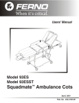
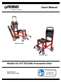
FERNO
®
When It’s Critical
®
Users’ Manual
Model 59-T Series
Model 59 Series
Models 59, 59-T EZ Glide® Evacuation Chair
May 2009 GLO
Pub. No. 234-3298-02
Read this Manual
and Retain for
Future Reference
59, 59-T EZ Glide®
Ferno Technical Support
Customer service and product support are important aspects of each
Ferno product. Please have the product serial number available
when calling, and include it in all written communications. For
technical support questions:
Telephone (Toll-free)
1.800.733.3766 ext. 1010
Telephone 1.937.382.1451 ext. 1010
Email
[email protected]
Ferno Customer Relations
For ordering assistance or general information:
Canada and the U.S.A.
Telephone (Toll-free)
Telephone Fax (Toll-free)
Fax
1.877.733.0911
1.937.382.1451
1.888.388.1349
1.937.382.1191
Internet
www.ferno.com
All Other Locations
For assistance or information, please contact your Ferno distributor.
If you do not have a Ferno distributor, please contact Ferno
Customer Relations:
Ferno-Washington, Inc.
70 Weil Way
Telephone Fax
Wilmington, Ohio 45177-9371, U.S.A.
+1.937.382.1451
+1.937.382.6569
Internet
www.ferno.com
European Representative
Ferno (UK) Limited
Stubs Beck Lane, Cleckheaton
West Yorkshire BD19 4TZ, United Kingdom
Telephone
+44 (0) 1274 851999
Fax
+44 (0) 1274 851111
Internet
www.ferno.co.uk
Disclaimer
This manual contains general instructions for the use, operation
and care of this product. The instructions are not all-inclusive. Safe
and proper use of this product is solely at the discretion of the
user. Safety information is included as a service to the user. All
other safety measures taken by the user should be within and under
consideration of applicable regulations. It is recommended that
training on the proper use of this product be provided before using
this product in an actual situation.
Retain this manual for future reference. Include it with the product
in the event of transfer to new users. Additional free copies are
available upon request from Customer Relations.
Serial Number _________________________
Location: Rear of Seat Panel Frame
users’ manual
and training cd-roms
To request additional free users’
manuals or training CD-ROMs,
contact Ferno Customer Relations,
your Ferno distributor, or visit
www.ferno.com.
Proprietary Notice
The information disclosed in this manual is the property of FernoWashington, Inc., Wilmington, Ohio, USA. Ferno-Washington, Inc.
reserves all patent rights, proprietary design rights, manufacturing
rights, reproduction use rights, and sales use rights thereto, and
to any article disclosed therein except to the extent those rights
are expressly granted to others or where not applicable to vendor
proprietary parts.
Limited Warranty Statement
The products sold by Ferno are covered by a limited warranty,
which is printed on the invoice you received when you purchased
the product. Please refer to the warranty terms as printed on
your invoice. The complete terms and conditions of the limited
warranty, and the limitations of liability and disclaimers, are also
available upon request by calling Ferno at 1.800.733.3766 or
1.937.382.1451.
© Copyright Ferno-Washington, Inc. All Rights Reserved.
2
© Ferno-Washington, Inc 234-3298-02 May 2009
59, 59-T EZ Glide®
Table of Contents
Section
Page
Ferno Technical Support________________________ 2
Ferno Customer Relations_______________________ 2
Illustrations____________________________________ 4
1 - Safety Information____________________________ 5
1.2 Important________________________________ 5
1.2 Warning_________________________________ 5
1.3 Bloodborne Disease Notice__________________ 5
1.4 Symbol Glossary__________________________ 5
1.5 Safety and Instruction Labels ________________ 5
2 - Operator Skills and Training___________________ 7
2.1 Skills___________________________________ 7
2.2 Training_________________________________ 7
3 - About the Chair______________________________ 8
3.1 Chair Description_ ________________________ 8
3.2 General Specifications_ ____________________ 8
3.3 Components - Model 59-T and Model 59_______ 9
4 - Chair Setup_ _______________________________ 10
4.1 Restraint Configurations for
Chair with ABS Panels____________________ 10
4.2 Using One-Piece Restraints_ _______________ 10
4.3 Ankle Restraint__________________________ 11
4.4 Attaching Restraints to Chair
With Soft Vinyl Seating_ __________________ 11
5 - Using the Features___________________________ 12
5.1 Chair Lock Bar__________________________ 12
5.2 Track System - Model 59-T Only____________ 13
5.3 Extending Lift Bar_ ______________________ 14
5.4 Telescoping Lift Handles_ _________________ 14
5.5 Footrest________________________________ 15
5.6 Wheel Locks____________________________ 15
6 - Using the Chair_ ____________________________ 16
6.1 Before Placing the Chair in Service__________ 16
6.2 General Guidelines for Use_________________ 16
© Ferno-Washington, Inc 234-3298-02 May 2009
Section
Page
6.3 Transferring the Patient____________________ 17
6.4 Rolling the Chair_________________________ 17
6.5 Gliding the Chair Down Stairs Model 59-T Only_ _______________________ 18
6.6 Transporting the Patient
Down Stairs - Model 59 Only_______________ 20
6.7 Transporting the Patient Up Stairs
Models 59-T and 59_ _____________________ 21
6.8 Using Additional Help_ ___________________ 22
7 - Maintenance________________________________ 23
7.1 Maintenance Schedule_ ___________________ 23
7.2 Disinfecting/Cleaning Restraints_ ___________ 23
7.3 Disinfecting/Cleaning Chair________________ 23
7.4 Cleaning Track and Belts_ _________________ 23
7.5 Inspecting the Chair_ _____________________ 24
7.6 Lubricating the Chair Model 59-T and Model 59 _________________ 25
7.7 Do Not Lubricate Track System
on Model 59-T_ _________________________ 25
7.8 Adjusting Track-Belt Tension_______________ 26
7.9 Reconditioning the Track Belts______________ 28
7.10 Removing and Attaching the ABS Panels _____ 29
7.11 Removing and Attaching
the Soft Vinyl Seating _ ___________________ 30
8 - Accessories and Related Products_ _____________ 31
8.1 EZ Glide Chair Accessories_ _______________ 31
8.2 Restraints_______________________________ 31
9 - Parts and Service____________________________ 32
9.1 U.S.A. and Canada_______________________ 32
9.2 Worldwide______________________________ 32
9.3 Parts List_______________________________ 32
9.4 Parts Diagrams_ _________________________ 33
Training Record_ ______________________________ 34
Maintenance Record____________________________ 35
3
59, 59-T EZ Glide®
Illustrations
Safety Labels
6, 7
Components - Model 59-T and Model 59
9
Figure 1 - Horizontal Restraint Configuration
10
Figure 2 - Criss-Cross Restraint Configuration
10
Figure 3 - Top: Correctly Wrapped One-Piece Restraint
Inset: Restraint Buckled
10
Figure 4 - Threading Buckle Through Loop
11
Figure 5 - Tightening Strap 11
Figure 6 - Ankle Restraint Attached
11
Figure 7 - Torso Restraints on Chair
with Soft Vinyl Seating
11
Figure 8 - Aligning the Wheels
12
Figure 9 - Disengaging the Lock
12
Figure 10 - Folding the Chair
12
Figure 11 - Engaging the Lock
12
Figure 12 - Opening the Track
13
Figure 13 - Closing the Track
13
Figure 14 - Left: Lift-Bar Positions
Inset: Adjusting Lift Bar Height
14
Figure 15 - Right: Lift Handle Positions
Inset: Extending/Retracting a Lift Handle 14
Figure 16 - Footrest Folded for Storage
15
Figure 17 - Footrest Lowered for Use
15
Figure 18 - Wheel Lock Engaged
15
Figure 19 - Wheel Lock Disengaged
15
Figure 20 - Patient Secured in Chair with Restraints
17
Figure 21 - Rolling the Chair
17
Figure 22 - Gliding the Chair Down a Curb
17
Figure 23 - Preparing Model 59-T for Descent
18
Figure 24 - Track Belts Engaging Top Step
18
4
Figure 25 - Establishing the Glide Angle
19
Figure 26 - Preparing to Roll the Chair
19
Figure 27 - Pausing on the Stairs
19
Figure 28 - Carrying the Model 59 Chair Down Stairs 20
Figure 29 - Pausing on the Stairs - Model 59 Chair
20
Figure 30 - Preparing to Carry Model 59-T (Tracked)
Chair Up Stairs
21
Figure 31 - Carrying Model 59 (Untracked)
Chair Up Stairs
21
Using Additional Help
22
Minimum Maintenance Intervals
23
Figure 32 - Top: Lubrication Point Locations
Bottom: Lubrication Point Close-up
25
Figure 33 - Label on Chair Track
25
Figure 34 - Chair Ready for Tensioning Procedure
26
Figure 35 - Belt Ready for Tensioning
26
Figure 36 - Tensioning the Belt
26
Figure 37 - Checking Tension with Chair Laying on Its
Tracks on a Work Bench
27
Figure 38 - Checking Tension
with Chair Standing on Its Wheels
27
Figure 39 - Marking Starting Point for Sanding Belt
28
Figure 40 - Sand in Direction of Arrows
28
Figure 41 - Releasing a Bottom Corner of Backrest
29
Figure 42 - Lifting the Backrest Panel Over the Keepers29
Figure 43 - Releasing a Corner of the Seat Panel
29
Figure 44 - Unfasten Snaps
30
Figure 45 - Unbuckle Straps
30
Figure 46 - Unfasten Seat Snaps
30
Figure 47 - Tighten Straps
30
Parts Diagrams 33
© Ferno-Washington, Inc 234-3298-02 May 2009
59, 59-T EZ Glide®
Safety Information
1 - Safety Information
1.1 Warning
1.3Bloodborne Disease Notice
Warning notices indicate a potentially hazardous situation
which, if not avoided, could result in injury or death.
To reduce the risk of exposure to bloodborne diseases such
as HIV-1 and hepatitis when using the chair, follow the
disinfecting and cleaning instructions in this manual.
Warning
Untrained operators can cause injury or be injured. Permit
only trained personnel to operate the chair.
Improper use of the chair can cause injury. Use the chair
only for the purpose described in this manual.
Attaching one-piece restraints improperly can allow seat
and back panels to dislodge, resulting in injury. Restraints
must capture panels AND chair frame.
1.4 Symbol Glossary
The symbols defined below are used on the chair and in
this users’ manual. Ferno uses symbols recognized by the
International Standards Organization (ISO), American
National Standards Institute (ANSI) and the emergency
medical services industry.
Using the chair with the track unlocked can cause injury.
Verify that the track is locked before transporting the
patient.
Lubricating the track system can result in injury to the
patient and/or operators. Never lubricate the track or
belts.
500 lb
227 kg
General Warning of
Potential Injury
Load Limit
Improper operation can cause injury. Operate the chair
only as described in this manual.
2
An unattended patient can be injured. Stay with the
patient at all times.
An unrestrained patient can fall off the chair and be
injured. Use restraints to secure the patient on the chair.
Helpers can cause injury or be injured. Maintain control
of the chair, operate the controls, and direct all helpers.
Chair Operation Requires
Two Trained Operators
Read the Users’
Manual
Improper maintenance can cause injury. Maintain the
chair only as described in this manual.
Attaching improper items to the chair can cause injury.
Use only Ferno-approved items on the chair.
Unlocked
Improper parts and service can cause injury. Use only
Ferno parts and Ferno-approved service on the chair.
Locked
Do Not
Lubricate
Lubricate
Modifying the chair can cause injury and damage. Use the
chair only as designed by Ferno.
1.2Important
Important notices emphasize important usage or maintenance
information.
Important
Open Track
System
Close Track
System
Product meets
European Union
Standards
1.5 Safety and Instruction Labels
Safety and instruction labels place important information
from the users’ manual on the chair.
Read and follow label instructions. Replace worn or
damaged labels immediately. New labels are available
from EMSAR (page 32), Ferno, or your Ferno distributor
(page 2). The labels illustrated on pages 6 and 7 are affixed
to the chair.
© Ferno-Washington, Inc 234-3298-02 May 2009
5
59, 59-T EZ Glide®
Safety Information
1.5 Safety and Instruction Labels (continued)
Model 59-t evacuation chair labels
Label A
Basic Safety Guidelines and Load Limit
Label B
Instruction for Adjusting Lift Bar Height
Label C - Instruction for Folding and Unfolding Chair
Label D
Safety Instruction:
Do NOT Lubricate
Track System
Label F
Instruction for
Closing Track
Label E - Instruction for Opening Track
Label 234-1440-00 Safety Instruction:
How to Attach One- and Two-Piece Restraints
6
© Ferno-Washington, Inc 234-3298-02 May 2009
59, 59-T EZ Glide®
Operator Skills and Training
1.5 Safety and Instruction Labels (continued)
model 59 evacuation chair labels
Label J
Basic Safety Guidelines and Load Limit
Label B
Instruction for Adjusting Lift Bar Height
Label C - Instruction for
Folding and Unfolding Chair
Label 234-1440-00
Safety Instruction: How to Attach
One- and Two-Piece Restraints
2 - Operator Skills and Training
2.1 Skills
Operators using the chair need:
●
a working knowledge of emergency patient-handling
procedures.
●
the ability to assist the patient.
Warning
Untrained operators can cause injury or be injured.
Permit only trained personnel to operate the chair.
2.2 Training
Operator trainees need to:
●
read and understand this manual.
●
be trained on the use of the chair.
●
practice with the chair before using it with a patient.
●
record their training information. A sample training
record sheet is provided on page 34.
© Ferno-Washington, Inc 234-3298-02 May 2009
7
59, 59-T EZ Glide®
About the Chair
3 - About the Chair
3.1 Chair Description
The Model 59-T and Model 59 EZ Glide® Evacuation Chairs
(referred to as the chair in this manual) are emergency
patient-handling devices designed to transport a seated
patient up and down stairs and over flat surfaces.
The chair is for professional use by a minimum of two
trained operators. A third person to “spot” may be required
by local protocols, and additional help may be required
when working with heavy patients.
The Model 59-T is designed with belted tracks that enable
operators to “glide” the chair down stairs instead of carrying
it. The Model 59 is untracked and is carried down stairs.
Chair features:
●
Belted track system for “gliding” chair down stairs
(Model 59-T only)
●
Choice of molded ABS seat and back panels or soft
vinyl seating
●
Choice of color
●
5-position extending lift bar at rear of chair
●
5-position telescoping front lift handles
●
6" rear locking wheels
●
4" front swivel wheels
●
Folding footrest
●
Ankle restraint
●
Multiple patient restraint options
Warning
Improper use of the chair can cause injury. Use the
chair only for the purpose described in this manual.
3.2 General Specifications
Height
Maximum
63.5 in/161 cm
Minimum
37.5 in/95 cm
Width
Overall
20.313 in/51.6 cm
Seat
16.5 in /42cm
Depth (front to back, Model 59-T)
Tracks Closed, Handles Retracted
28 in/73 cm
Tracks Open, Handles Extended
51 in/130 cm
Depth (front to back, Model 59)
Handles Retracted
27 in/69 cm
Handles Extended
40 in/102 cm
Folded (Model 59-T)
37.5 in x 20.313 in x 8 in
95 cm x 51.6 cm x 20 cm
Folded (Model 59) 37.5 in x 20.313 in x 7 in
95 cm x 51.6 cm x 18 cm
Weight*
Model 59-T
33 lb/15 kg
Model 59
26 lb/12 kg
Load Limit
500 lb/227 kg
* without restraints or accessories
●
Rear lift handles, locking or non-locking
Some specifications are rounded to the nearest whole number.
Metric conversions are calculated before rounding the Imperial
measurements. For more information, contact Ferno Customer
Relations (page 2).
●
IV bag holder
Ferno reserves the right to change specifications without notice.
●
O2 bottle holder
●
Headrest (head pad with strap)
●
Kwik Klip™ Restraint System
●
Secure Mount (with spring release) for storing chair in
ambulance or station
●
Bracket (with hooks) for storing chair in station
Optional Accessories:
8
LOAD LIMIT
500 lb
227 kg
Inspect the chair if the load
limit has been exceeded (see
Inspecting the Chair, page 24).
© Ferno-Washington, Inc 234-3298-02 May 2009
59, 59-T EZ Glide®
About the Chair
3.3 Components - Model 59-T and Model 59
Components of both chair models are the same except for those parts
marked “59-T Only.”
Track-Release Bar
59-T Only
Model 59
Extending
Lift Bar
Lift Bar Release
Model 59-T
Track-Closing
Handle
59-T Only
Removable
ABS Back Panel
with Restraint
Slots
Removable
ABS Seat Panel
with Restraint
Slots
Patient
Restraint
Track Belt (2)
59-T Only
Ankle
Restraint
Track
59-T Only
Telescoping
Lift Handle (2)
6" Wheel
with Lock (2)
4" Swivel
Wheel (2)
Folding
Footrest
Chair
Lock Bar
Soft Vinyl Seating Option
59-T and 59
restraint
options
Users’ Manual
6
el 41
Mod
nt
strai
Re
ated
Co
To request additional free
users’ manuals, contact
Ferno Customer Relations
(page 2).
0
el 43
Mod
el
Mod
© Ferno-Washington, Inc 234-3298-02 May 2009
P
430-
9
59, 59-T EZ Glide®
Chair Setup
4 - Chair Setup
4.1Restraint Configurations for
Chair with ABS Panels
Figure 1 - Horizontal
Restraint Configuration
Follow local protocols when choosing a configuration. Two
possible configurations are described below.
Horizontal Configuration
Use one restraint for the chest and one restraint for the lap
(Figure 1).
1. Attach the chest straps through matching horizontal or
vertical slots in the backrest panel.
2. Attach the lap straps through the seat panel slots.
Criss-Cross Configuration
Use two restraints for the torso. Ferno recommends using a
third restraint for the lap (Figure 2).
1. Attach one strap of a restraint through a vertical slot
on the backrest panel of the chair.
Figure 2 - Criss-Cross
Restraint Configuration
with Lap Belt
2. Attach the other strap of the restraint through the seat
panel slot on the opposite side of the chair.
3. Repeat with the second restraint, attaching its straps to
opposite sides of the chair.
4. Attach the lap restraint through the seat-panel slots.
Warning
Attaching one-piece restraints improperly can allow
seat and back panels to dislodge, resulting in injury.
Restraints must capture panels AND chair frame.
4.2 Using One-Piece Restraints
Ferno recommends using two-piece restraints with the
backrest and seat panels, but if you choose to use onepiece restraints, they must capture both the panel and
frame, as follows:
1. Work from the patient side of the panel and feed the
ends of the restraint through the slots on opposite sides
of the panel.
2. Wrap the restraint around the aluminum chair frame,
capturing the panel and the frame (Figure 3 Top).
3. Buckle the restraint (Figure 3 Inset) and adjust the
length.
10
Figure 3 - Top: Correctly Wrapped Restraint
Inset: Restraint Fastened
© Ferno-Washington, Inc 234-3298-02 May 2009
59, 59-T EZ Glide®
Chair Setup
4.3Ankle Restraint
Attach the two-piece ankle restraint to the front legs of the
chair. To attach the restraint:
1. Unbuckle the restraint to separate the straps.
2. Wrap a strap around one front leg of the chair and
thread the buckle through the loop (Figure 4).
3. Pull the strap until the looped end is tight around the
chair leg (Figure 5).
4. Attach the remaining strap to the other front leg of the
chair.
5. Buckle the restraint and adjust the length (Figure 6).
Figure 4 - Threading Buckle Through Loop
4.4Attaching Restraints to Chair With Soft Vinyl Seating
With soft vinyl seating, use the criss-cross restraint
configuration plus a lap restraint (Figure 2, page 10). To
attach the restraints:
1. Unbuckle a restraint to separate the straps.
2. Attach the strap with the female buckle piece to the left
or right side of the backrest frame (Figure 7). Follow
instructions in the restraint users’ manual for attaching
a two-piece restraint.
Figure 5 - Tightening Strap
3. Attach the strap with the male buckle piece to the
exposed area of the seat frame on the opposite side of
the chair.
4. Repeat steps 1-3 to attach the second torso restraint.
5. Attach a lap restraint alongside the restraints already
attached to the seat frame.
6. Fasten and adjust the restraints.
Figure 6 - Ankle Restraint Attached
Figure 7 - Torso Restraints on Chair
with Soft Vinyl Seating
© Ferno-Washington, Inc 234-3298-02 May 2009
11
59, 59-T EZ Glide®
Using the Features
5 - Using the Features
5.1 Chair Lock Bar
The red lock bar below the front edge of the seat disengages
the lock for folding and unfolding the chair. Before seating a
patient, verify that the chair is completely unfolded and the
lock is engaged.
folding the chair
Swivel
Wheels
Reversed
1. Buckle the restraints and adjust them to prevent
interference when folding the chair.
2. Roll the chair backward a foot or two to reverse the
swivel wheels (Figure 8).
3. Stand at the side of the chair and grasp the chair
backrest with one hand and the lock bar with the other
hand (Figure 9).
Lock Bar
Figure 8 - Aligning
the Wheels
Figure 9 - Disengaging
the Lock
Figure 10 - Folding
the Chair
Figure 11 - Engaging
the Lock
4. Pull the lock bar forward, then begin folding the seat
toward the backrest.
As you fold the seat, tilt the chair forward a little
(Figure 10) to keep the front wheels turned outward
so they will not hold the frame away from the seat and
prevent the lock from engaging.
5. Press the seat against the backrest until the lock
engages (Figure 11).
6. Verify the lock is engaged by pulling the seat away
from the backrest without pulling the lock bar. The
seat will not move if the lock is engaged.
unfolding the chair
1. Stand beside the chair and grasp the backrest with one
hand and the lock bar with the other hand.
2. Pull the lock bar forward, then pull the seat away from
the backrest until it is fully unfolded and the lock
engages.
3. Verify that the lock has engaged by holding the
backrest in place while pulling up on the chair frame
at the front of the seat without pulling the lock bar. The
chair will not fold if the lock is engaged.
12
Important
The chair lock must be disengaged before beginning
to fold or unfold the chair. Pull the lock bar forward,
then begin to fold or unfold the chair.
© Ferno-Washington, Inc 234-3298-02 May 2009
59, 59-T EZ Glide®
Using the Features
5.2 Track System - Model 59-T Only
The Model 59-T track system enables operators to glide the
chair down stairs instead of lifting and carrying it.
guidelines for using the track system
●
Using the chair on stairs requires a minimum of two
trained operators. Ferno recommends using a third
person as a “spotter” (see Gliding the Chair Down
Stairs, page 18).
●
Verify that the track system is fully opened and locked
into place before using it.
●
Never lubricate track belts. Lubricated track belts can
perform unpredictably, resulting in injury to the patient
and/or operators.
●
Moisture, water, snow, ice, or debris on or between the
track and belts can cause irregular track-belt performance
that results in sudden changes in the weight operators
must support. Make sure the track and track belts are
clean and dry before using the chair on stairs.
●
Water, snow, ice, or debris on the stairs can cause poor
footing for operators. To avoid possible injury, clear
the stairs or select an alternate route.
Figure 12 - Opening the Track
opening the track
1. Grasp the track-release bar located
near the top of the track (Figure
12) and firmly pull it back until the
track locks into the fully extended
position.
2. Verify that the lock is engaged by
trying to push the track closed. If the
lock is fully engaged the track will
not move.
Open Track
System
Figure 13 - Closing the Track
Warning
closing the track
With your hand, push down on the red
track-closing handle (Figure 13) until the
track closes completely.
Close Track
System
Using the chair with the track unlocked can cause
injury. Verify that the track is locked before
transporting the patient.
Warning
Lubricating the track system can result in injury to
patient and/or operators. Never lubricate the track
or belts.
© Ferno-Washington, Inc 234-3298-02 May 2009
13
59, 59-T EZ Glide®
Using the Features
5.3 Extending Lift Bar
Grasp the lift bar to move and guide the chair as you glide it
down stairs, carry it up stairs or over obstacles, and roll it.
The lift bar adjusts to five locked positions (Figure 14, Left).
Adjust the height according to operator preference and the
task or situation at hand.
extending and retracting the lift bar
1. With one hand, squeeze the lift-bar release tabs
together and with the other hand grasp the lift bar and
raise or lower it (Figure 14, Inset).
2
2. Verify that the lift bar is locked by trying to raise or
lower it without squeezing the release tabs. When the
lock is engaged the lift bar will not move.
1
Figure 14 - Left: Lift-Bar Positions
Inset: Adjusting Lift- Bar Height
5.4 Telescoping Lift Handles
The telescoping lift handles can be adjusted to five locked
lifting positions (Figure 15, Right). Adjust the handles
according to operator preference and the task at hand.
extending and retracting
the lift handles
1
2
1. Press the release button (Figure 15, Inset) and push or
pull the handle until it is near the stop point desired.
2. Release the button and slide the handle a little forward
or backward until it locks into the stop point.
3. Verify that both handles are locked by trying to push or
pull them without pressing the release buttons. When
the locks are engaged, the handles will not move.
Figure 15 - Right: Lift-Handle Positions
Inset: Extending/Retracting a Lift Handle
14
© Ferno-Washington, Inc 234-3298-02 May 2009
59, 59-T EZ Glide®
Using the Features
5.5 Footrest
Figure 16 - Footrest
Raised for Storage
The footrest has two positions: raised, for storage, (Figure
16) and lowered for use (Figure 17).
To lower the footrest, swing it down until it stops.
To raise the footrest, swing it up until it stops.
Guidelines for Using the footrest
Use the footrest properly to ensure that is does not interfere
with patient’s or operators’ feet.
●
Before transferring the patient onto the chair, make
sure the footrest is raised in the storage position.
●
When preparing to transfer the patient off the chair,
unfasten the ankle restraint and raise the footrest into
the storage position before unfastening the patient’s
torso and lap restraints. This will prevent the patient
from attempting to stand before the footrest has been
stored out of the way of his/her feet.
●
Keep the footrest raised when it is not in use.
Figure 17 - Footrest
Lowered for Use
Important
Raise the footrest into the storage position before
transferring the patient onto or off from the chair.
5.6 Wheel Locks
The rear wheels of the chair are fitted with wheel locks to
help keep the chair from rolling during patient transfer.
Stay with the chair and maintain control of it at all times. Do
not use the wheel locks as a substitute for operator control.
To engage a wheel lock, press down on the rear end of the
lock pedal (Figure 18).
To disengage a wheel lock, press down on the forward end
of the lock pedal (Figure 19).
© Ferno-Washington, Inc 234-3298-02 May 2009
Figure 18 - Wheel Lock
Engaged
Figure 19 - Wheel Lock
Disengaged
15
59, 59-T EZ Glide®
Using the Chair
6 - Using the Chair
6.1Before Placing the Chair
in Service
●
Personnel who will work with the chair need to read
this manual.
●
Set up the chair, following the instructions in Chair
Setup (pages 10, 11).
●
Confirm that the chair operates properly. See Inspecting
the Chair, page 24.
6.2 General Guidelines for Use
●
Medical advice is beyond the parameters of this
manual.
●
It is the users’ responsibility to ensure safe practices
for the patient and themselves.
●
A minimum of two trained operators is required.
●
Follow standard emergency patient-handling
procedures when operating the chair.
●
Operators work together and maintain control of
the chair at all times.
●
Operators communicate with one another and use
coordinated movements to operate the chair.
●
Ferno recommends that a third trained person serve as
a “spotter” while the chair is being moved up or down
stairs.
●
Lift only the weight you can safely handle. Use
additional help when working with heavy loads
(patient and equipment). For placement of help, see
Using Additional Help, page 22.
●
Stay with the patient at all times.
●
Always use patient restraints to secure the patient on
the chair.
16
Warning
Improper operation can cause injury. Operate the
chair only as described in this manual.
Warning
An unattended patient can be injured. Stay with the
patient at all times.
Warning
An unrestrained patient can fall off the chair and be
injured. Use restraints to secure the patient on the
chair.
© Ferno-Washington, Inc 234-3298-02 May 2009
59, 59-T EZ Glide®
Using the Chair
6.3 Transferring the Patient
Always assist the patient onto and off from the chair.
assisting the patient onto the chair
1. Unfold the chair and verify that it is locked.
2. Engage the locks on the rear wheels.
3. Make sure the footrest is in the storage position.
4. Assist the patient onto the chair using accepted
practices and following local protocols.
Figure 20 - Patient
Secured in Chair
with Restraints
5. Fasten and adjust the torso and lap restraints.
6. Lower the footrest and place the patient’s feet on it.
7. Fasten and adjust the ankle restraint (Figure 20).
assisting the patient off from the chair
1. Unfasten the ankle restraint.
2. Raise the footrest to the storage position.
3. Unfasten the torso and lap restraints.
4. Assist the patient off from the chair using accepted
practices and following local protocols.
6.4Rolling the Chair
Figure 21 - Rolling
the Chair
general guidelines
●
Roll the chair on smooth, flat surfaces whenever
possible (Figure 21).
●
For patient comfort, pull the chair backward over low
obstacles such as door sills.
●
Use the extending lift bar and telescoping foot-end
handles to lift and carry the Model 59 chair over curbs,
obstacles, rough surfaces and rough terrain.
●
Use the tracks on the Model 59-T chair to “glide” the
chair down over curbs or single steps (Figure 22).
To roll the chair
1. Head-End Operator: Release the wheel locks.
2. Head-End Operator: Adjust the lift bar to a
comfortable height and grasp it to push and guide the
chair on all four wheels (Figure 21), or tilt the chair
back and roll it on its rear wheels.
3. Foot-End Operator: Assist the head-end operator as
needed and attend the patient.
Figure 22 - Gliding the Chair Down a Curb
© Ferno-Washington, Inc 234-3298-02 May 2009
17
Using the Chair
6.5 Gliding the Chair Down Stairs - Model 59-T Only
General guidelines
●
Using the chair on stairs requires a minimum of two
operators. Use additional help as needed to control the
chair (see Using Additional Help, page 22).
●
Ferno recommends that the two operators face each
other when transporting a patient down stairs and that
a third trained person “spot” for the foot-end operator.
However, the foot-end operator may face forward
(with back to patient) if desired. Follow your local
protocols for carrying chairs.
●
Remove any water, ice, snow, or debris from the stairs
before using the chair on them.
●
Remove any water, ice, snow, or debris from the track
and tread belts before using the chair on stairs.
●
Verify that the track is locked in the open position
before starting down the stairs with the chair.
59, 59-T EZ Glide®
Warning
Using the chair with the track unlocked can cause
injury. Verify that the track is locked before
transporting the patient.
Warning
Lubricating the track system can result in injury to
patient and/or operators. Never lubricate the track
or belts.
gliding the chair down stairs
1. Head-End Operator: Roll the chair to the stairs and
engage the wheel locks.
2. Foot-End Operator: Extend the foot-end lift handles
to the desired stop point. Verify that both handles are
locked.
Figure 23 - Preparing Model 59-T for the Descent
3. Spotter: Stand below the foot-end operator with a
hand on the operator's back to help steady and guide
him/her throughout the descent.
4. Head-End Operator: Pull the track system toward
yourself until the track locks open. Verify that the
track is locked.
5. Head-End Operator: Raise the lift bar to the desired
position and verify that it is locked (Figure 23).
6. Head-End Operator: Disengage the wheel locks
(Figure 23) and tilt the chair back.
7. Both Operators: Working together, guide the chair
over the edge of the top step, allowing the track belts
to engage the step (Figure 24).
18
Figure 24 - Track Belts Engaging Top Step
© Ferno-Washington, Inc 234-3298-02 May 2009
59, 59-T EZ Glide®
Using the Chair
8. Move the chair slowly downward until the tracks are
resting on the top two or three steps. This establishes
the glide angle (Figure 25).
9. To maintain the glide angle as you descend, work
together as follows:
○○
The head-end operator applies slight downward
pressure on the extended lift bar.
○○
The foot-end operator applies slight upward
pressure on the foot-end lift handles.
10. Both Operators: When the chair reaches the bottom
of the steps and the rear wheels are on the floor, the
head-end operator tips the chair forward until all four
wheels are on the floor and the foot-end operator
retracts the lift handles (Figure 26).
11. Head-End Operator: Close the tracks and adjust the
lift bar to a comfortable height, then roll the chair.
Figure 25 - Establishing
the Glide Angle
To Pause During the Descent
To pause during the descent, tilt the chair forward
just enough to allow the rear wheels to rest on the
step while both operators hold the chair in place
(Figure 27).
To continue down the stairs, tilt the chair back to the
glide angle and engage the belts on the steps.
Figure 26 Preparing to
Roll the Chair
Figure 27 - Pausing on the Stairs
© Ferno-Washington, Inc 234-3298-02 May 2009
19
Using the Chair
59, 59-T EZ Glide®
6.6 Transporting the Patient
Down Stairs - Model 59 Only
General guidelines
●
Carrying the chair down stairs requires a minimum
of two operators. Use additional help as needed (see
Using Additional Help, page 22).
●
Ferno recommends that the two operators face each
other when transporting a patient down stairs and
that a third person “spot” for the foot-end operator.
However, the foot-end operator may face forward
(with back to patient) if desired. Follow your local
protocols for carrying chairs.
carrying the chair down stairs
1. Head-End Operator: Roll the chair to the stairs and
engage the wheel locks.
2. Foot-End Operator: Extend the foot-end lift handles
to the desired stop point. Verify that both handles are
locked and maintain your grasp.
3. Spotter: Stand below the foot-end operator with a
hand on the operator’s back to help steady and guide
him/her throughout the descent.
4. Head-End Operator: Raise the lift bar to the desired
position and verify that it is locked.
Figure 28 -Carrying the
Model 59 Chair Down Stairs
5. Head-End Operator: Disengage the wheel locks and
tilt the chair back.
6. Operators and Spotter: Operators work together to
lift the chair and carry it down the stairs. The spotter
keeps a hand on the foot-end operator’s back and
provides verbal guidance (Figure 28).
Note: To pause during the descent, allow the rear wheels
of the chair to rest on a step while both operators hold the
chair in place (Figure 29). To continue down the stairs, tilt
the chair back and lift and carry it.
7. Operators: At the bottom of the stairs, the operators
set the chair on the floor and retract the lift handles.
8. Head-End Operator: Adjust the lift bar to a
comfortable height before rolling the chair.
Figure 29 -Pausing on the Stairs - Model 59 Chair
20
© Ferno-Washington, Inc 234-3298-02 May 2009
59, 59-T EZ Glide®
Using the Chair
6.7 Transporting the Patient Up Stairs
Models 59-T and 59
General guidelines
●
Carrying the chair up stairs requires a minimum of two
operators. Use additional help as needed (see Using
Additional Help, page 22).
●
The two operators face each other when transporting
a patient up stairs. Ferno recommends that a third
person “spot” for the head-end operator. Follow your
local protocols for carrying chairs.
carrying the chair up stairs
1. Head-End Operator: Roll the chair to the bottom of the
stairs and position it with the patient’s back to the stairs.
2. Head-End Operator: Extend the lift bar to the desired
position and verify that it is locked.
3. Spotter: Stand above the head-end operator with a
hand on the operator’s back to help steady and guide
him/her throughout the ascent (Figure 30).
Figure 30 - Preparing to Carry
Model 59-T (Tracked) Chair Up Stairs
4. Foot-End Operator: Extend the foot-end lift handles
to the desired position and verify that both handles are
locked (Figure 30).
Important
5. Both Operators and Spotter: Working together, the
operators grasp the lift bar and lift handles and carry
the chair up the stairs. The spotter keeps a hand on
the head-end operator’s back and provides verbal
guidance (Figure 31).
The EZ Glide track system was designed to assist in
descending stairs. It can be used to ascend stairs, but
in some circumstances it may be easier to lift and/or
carry the chair up stairs.
6. Both Operators: At the top of the stairs, the head-end
operator sets the rear wheels of the chair on the floor
and rolls the chair backward until the front wheels are
securely on the floor.
7. Foot-end Operator: Retract the foot-end lift handles.
8. Head-End Operator: Adjust the lift bar to a comfortable
height before rolling the chair.
Figure 31 - Carrying Model 59
(Untracked) Chair Up Stairs
© Ferno-Washington, Inc 234-3298-02 May 2009
21
59, 59-T EZ Glide®
Using the Chair
6.8 Using Additional Help
Operating the chair requires a minimum of two trained operators. Ferno recommends that the operators and helpers at opposite
ends of the chair face each other when transporting a patient up or down stairs, and that a third trained person “spot” for the
lead operator. However, all applicable local protocols for carrying chairs should be followed.
The trained operators should maintain control of the chair and operate the controls, and the designated lead operator should
direct all helpers. The chart below shows suggested placement for operators and helpers.
Direction
Two
Operators
+
Two
Helpers
Direction
Two
Operators
+
One
Helper
LOAD LIMIT
Rolling on Flat Surface
500 lb
227 kg
Inspect the chair if the load limit has
been exceeded (see Inspecting the
Chair, page 24).
Warning
Helpers can cause injury or be injured. Maintain
control of the chair, operate the controls, and direct
all helpers.
Gliding Down Stairs on Track System
or
Carrying Chair Down Stairs
Carrying Chair Up Stairs
O
P
O
S
Two
Operators
+
Three
Helpers
Key: O = Operator H = Helper S = Spotter P = Patient
22
© Ferno-Washington, Inc 234-3298-02 May 2009
59, 59-T EZ Glide®
Maintenance
7 - Maintenance
When using maintenance products, follow the manufacturers’
directions and read the manufacturers’ material safety data
sheets. You can purchase a recommended disinfectant from
your Ferno distributor or Ferno Customer Relations (page 2).
Disinfecting Chair (this page)
Cleaning Chair (this page)
Cleaning Track System (this page)
Inspecting Chair (page 24)
Inspecting Track System (page 24)
7.2Disinfecting/Cleaning Restraints
Ankle Restraint: Place buckled restraint in a mesh bag
and launder in a washing machine using warm water, a
disinfectant soap, and gentle agitation. Hang the restraint to
dry. Do not put it in a dryer.
Chest and Lap Restraints: Disinfect and clean restraints as
directed in the restraint users’ manual provided. Additional,
free users’ manuals can be obtained from Ferno Customer
Relations (page 2).
7.3Disinfecting/Cleaning Chair
To disinfect: Remove restraints and seat and backrest
panels or soft vinyl cover. Wipe all surfaces of the chair and
panels or cover with disinfectant. Follow the disinfectant
manufacturer’s directions for application method and
contact time.
To clean: Wash panels or cover, and all parts of the chair,
with warm water and a mild detergent. Rinse with clean
water. Dry with a towel or allow to air-dry.
7.4 Cleaning Track and Belts
To ensure predictable belt performance, it is important to
keep the track and belts free of oil, grease, dirt, and debris.
1. Hold the belts away from the track frame and remove
any debris.
2. Clean both sides of the track frame, and both belts,
with SD-20 All-Purpose Cleaner and a clean cloth.
Follow instructions on the container.
3. Dry track and belts thoroughly.
•
Lubricating (page 25)
•
Each Month
Keep maintenance records. A sample maintenance record
sheet is provided on page 35.
Minimum
Maintenance Intervals
As Needed
The chair requires regular maintenance. Set up and follow
a maintenance schedule. The table at right represents
minimum intervals for maintenance.
Each Use
7.1 Maintenance Schedule
•
•
•
•
•
•
Warning
Improper maintenance can cause injury. Maintain
the chair only as described in this manual.
Important
Disinfectants and cleaners containing bleach,
phenolics, or iodines can cause damage. Use caution
when disinfecting and cleaning with products
containing these chemicals.
Important
Water under high pressure, or steam, can penetrate
joints, flush away lubricant, and cause corrosion. Use
caution when cleaning moving parts such as joints and
hinges.
Important
Using abrasive cleaning compounds or applicators
on the chair can cause damage. Do not use abrasive
materials to clean the chair.
Note: To order SD-20 Cleaner, call Spartan Chemical
Company at 1.800.537.8990.
© Ferno-Washington, Inc 234-3298-02 May 2009
23
59, 59-T EZ Glide®
Maintenance
7.5Inspecting the Chair
Have your service’s equipment maintenance personnel
inspect the chair at regular intervals. Track and track belts
should be inspected after each use.
Follow the checklists on this page and work the chair through
all its functions as described in this manual.
If inspection shows damage or excessive wear, remove the
chair from service until repairs are made. See Parts and
Service, pages 32 and 33.
inspection checklist
for model 59-T and model 59 chairs
●
Are all components present?
●
Is the chair free of excessive wear?
●
Are all screws, nuts, bolts, rivets, and roll pins
securely in place?
●
Do all moving parts operate smoothly and properly?
●
Do all locks on the chair operate properly?
●
Does the chair roll smoothly?
●
Are the restraints properly installed?
●
Is restraint webbing in good condition with no cuts
or frayed edges?
●
Are restraint buckles free of visible damage and do
they operate properly?
●
Do installed accessories operate properly without
interfering with chair operation?
inspection checklist
for track and belts
24
●
Are the track and belts free of lubricant, dirt and
debris?
●
Is there visible damage to the track or belts?
●
Are inner cords of belts visible (indicating the need
for replacement)?
●
Are the belt-tensioning bolts and nuts tight?
●
Do the belts roll properly?
●
Do the track and belts perform properly?
© Ferno-Washington, Inc 234-3298-02 May 2009
59, 59-T EZ Glide®
Maintenance
7.6Lubricating the Chair Model 59-T and Model 59
Disinfect and clean the chair before applying lubricant.
There are two identical lubrication points on the chair. They
are located where the brass bushing in the chair lock bar slot
meets the stainless steel slide in the chair leg (Figure 32).
Lubricate each lubrication point with one drop
of SAE 30-weight oil, then move the lock bar
back and forth a few times to work the oil into
the slide. Remove any excess lubricant with
Lubricate
SD-20 Cleaner.
Note: To order SD-20 Cleaner, call Spartan Chemical
Company at 1.800.537.8990.
Important
Lubricating parts that should not be lubricated allows
dirt and foreign particles to collect on those parts,
resulting in damage. Lubricate only the numbered
reference points shown.
Figure 32 Top: Lubrication Point Locations
Bottom: Lubrication Point Close-up
7.7Do Not Lubricate Track System
on Model 59-T
Never lubricate the track, the track belts, or any other
part of the track system. Lubricants on the belts or track
can cause the chair to perform unpredictably, resulting in
injury to the patient and/or operators.
A label (Figure 33) instructing the user not to lubricate the
track system is affixed to each side
of the track. If these labels become
damaged or worn, replace them
immediately (see Parts and Service,
page 32 and 33).
Do Not Lubricate
If track or belts pick up oil or grease
during use or while the chair is being serviced, clean the
track and belts with SD-20 All-Purpose Cleaner before using
the chair again. See Cleaning Track and Belts, page 23, for
cleaning instructions.
© Ferno-Washington, Inc 234-3298-02 May 2009
Warning
Lubricating the track system can result in injury to
patient and/or operators. Never lubricate the track
or belts.
Figure 33 - Label on Chair Track
25
Maintenance
59, 59-T EZ Glide®
7.8Adjusting Track-Belt Tension
when to adjust belt tension
Track belt tension needs to be adjusted when:
●
a nut and bolt become loose
●
a belt pulls away from the track more than 1-1/2 in.
(3.8 cm) when measured using Method 1 on Page 27.
●
a belt pulls away from the track more than 1 in. (2.5
cm) when measured using Method 2 on Page 27.
Important
Adjusting the belt tension is a two-person operation.
Tools Needed
2 ea
1 ea
1 ea
7/16-inch Wrench
#4 Phillips Screwdriver
Ruler or Measuring Tape
Figure 34 - Chair Positioned for Tensioning Procedure
(See Step 1 for Alternate Position)
#4 Phillips
Screwdriver in
Adjustment Slot
tension-adjustment
1. Open the track and lay the chair on its back on a
workbench as shown in Figure 34.
OR
Stand the chair on its wheels on a workbench, then
open the track and engage both wheel locks.
2. Loosen the bolt and black cap locking nut located at
the top end of the track (Figure 35).
3. Slide the #4 Phillips screwdriver into the adjustment
slot (Figure 35).
Loosened Bolt
Loosened
Black Cap
Locking Nut
(not visible in photo)
Figure 35 - Belt Ready for Tensioning
4. While one person tensions the belt by using the #4
Phillips screwdriver to pull the belt roller toward the
top of the track, the other person uses the two 7/16inch wrenches to tighten the bolt and nut only enough
to hold the tension (Figure 36).
Figure 36 - Tensioning the Belt
26
© Ferno-Washington, Inc 234-3298-02 May 2009
59, 59-T EZ Glide®
5. There are two methods for checking belt tension.
You can use whichever method you prefer, but do
not use the chair position from one method with the
measurement range from the other method.
6. Use Method 1 (below, left) if the chair is laying on its
tracks on a work bench. Use Method 2 (below, right)
if the chair is standing on its wheels.
Maintenance
7. It may be necessary to repeat the tensioning and
measuring one or more times to achieve the correct
belt tension.
8. When the belt tension is correct, finish tightening the
bolt and nut to maintain the tension.
9. Repeat Steps 2-6 to adjust the tension of the other
track belt.
Method 1
Method 2
Chair Must Be Laying on Its Tracks
on a Workbench
Chair Must Be Standing on Its Wheels
Grasp the belt at the track midpoint and pull the belt
away from the track to remove any slack, then measure
the distance between the exposed surface of the track
and the inner surface of the belt. Take the measurement
at the track midpoint.
The belt is correctly tensioned when the measurement
from the exposed surface of the track to the inner
surface of the belt is 1-1/4 in. to 1-1/2 in. (3.175 cm to
3.8 cm), as shown in Figure 37.
Figure 37 - Checking Tension with Chair
Laying on Its Tracks on a Work Bench
© Ferno-Washington, Inc 234-3298-02 May 2009
Grasp the belt at the track midpoint and pull the belt
away from the track to remove any slack, then measure
the distance between the exposed surface of the track
and the inner surface of the belt. Take the measurement
at the track midpoint.
The belt is correctly tensioned when the measurement
from the exposed surface of the track to the inner
surface of the belt is 3/4 in. to 1 in. (1.9 cm to 2.5 cm)
as in Figure 38.
Figure 38 - Checking Tension with Chair
Standing on Its Wheels
27
59, 59-T EZ Glide®
Maintenance
7.9Reconditioning the Track Belts
Track belts need reconditioning when the inner surface
becomes glassy or glazed. As this glazing occurs, the belts
begin to move less freely over the steps and the belt teeth
begin to skip, rather than roll, over the steps.
items required for reconditioning belts
1 ea
1 ea
1 ea
Permanent marker
50-80 grit sandpaper
Wood block
To recondition the belts:
1. Place the chair on a workbench.
2. Apply wheel locks.
3. Roll the belt away from the track and mark the inner
surface with a permanent marker to identify the starting
point for sanding (Figure 39).
Figure 39 - Marking the Starting Point
for Sanding the Belt
4. Place sanding block between belt and track and move
the block up and down to sand the inner surface of the
belt (Figure 40).
Note:
Take care not to sand the surface of the track.
5. Repeat Steps 3 and 4 with the other belt.
6. Secure a simulated patient weight to the chair and
glide the chair down a flight of stairs to test whether
the belts roll over the steps properly.
7. If the belts do not perform properly, you may need
to re-sand them, or they may need to be replaced.
See Parts and Service, pages 32 and 33, to order
replacement belts.
Figure 40 - Sand in Direction of Arrows
28
© Ferno-Washington, Inc 234-3298-02 May 2009
59, 59-T EZ Glide®
Maintenance
7.10Removing and Attaching
the ABS Panels
The molded ABS seat and backrest panels snap on and off
the chair frame.
backrest panel
To remove the backrest panel: gently pull downward on
the flange near one bottom corner and pull the corner of
the panel away from the chair (Figure 41). Repeat at the
opposite corner. Then slide the panel up off the two keepers
at the top of the frame (Figure 42).
To attach the backrest panel: Orient the panel with the
horizontal restraint slots uppermost. Slide the two holes
in the top flange down over the keepers on the top of the
backrest frame, then press both lower corners of the panel
against the sides of the frame until they snap into place over
their keepers.
seat panel
To remove the seat panel: Pull upward on the panel flange
at each front corner to pop the panel free of the seat frame
(Figure 43) then lift the panel off the chair.
Figure 41 - Releasing a Bottom Corner of the Backrest
To attach the seat panel: Align the panel with the chair
frame and press down to snap the panel onto the frame.
Figure 42 - Lifting the Backrest Panel Over the Keepers
Figure 43 - Releasing a Corner of the Seat Panel
© Ferno-Washington, Inc 234-3298-02 May 2009
29
59, 59-T EZ Glide®
Maintenance
7.11Removing and Attaching
the Soft Vinyl Seating
Snaps
To remove the seating:
1. Unfasten the snap at each corner of the vinyl at the top
of the backrest (Figure 44).
2. Lay chair on its back and unbuckle both retaining
straps beneath the seat (Figure 45).
3. Unfasten the four snaps on the vinyl flap beneath the
seat at the front of the chair (Figure 46).
4. Lift the cover off the chair and return the chair to the
upright position.
Figure 44 - Unfasten Snaps
To attach the seating:
1. Fasten the snap at each corner of the vinyl at the top
of the backrest.
2. Lay chair on its back and fasten the buckles of both
retaining straps.
3. Fasten the four snaps on the vinyl flap beneath the seat
at the front of the chair.
Figure 45 Unbuckle Straps
4. Pull the free end of each buckled retaining strap until
the strap is tight (Figure 47), then return the chair to
the upright position.
Snaps
Figure 46 - Unfasten Seat Snaps
Figure 47 - Tighten
Straps
30
© Ferno-Washington, Inc 234-3298-02 May 2009
59, 59-T EZ Glide®
Accessories
8 - Accessories and Related Products
Ferno offers a full line of emergency medical service accessories
(fasteners, IV poles, immobilizers, blankets, etc.). Selected items
approved for use with the chair are listed here.
Warning
Always follow the instructions packed with accessories. Keep the
instructions with this manual. Be aware of any special considerations
(loading heights, door widths, etc.) when using accessories.
Attaching improper items to the chair can
cause injury. Use only Ferno-approved items
on the chair.
For product information, contact Ferno Customer Relations (page 2).
8.1 EZ Glide Chair Accessories
Description
Kwik Klip™ Restraint System
IV Bag Holder Complete
IV Bag Holder Replacement Strap
Headrest Complete
Head Strap Replacement
EZ Glide® Oxygen Cylinder Holder
Oxygen Cylinder Replacement Straps
Non-Locking Rear Lift Handle
Pair
Right
Left
Locking Rear Lift Handles
Pair
Right
Left
Secure Mount Storage Brackets
(with spring release)
Storage Bracket (with hooks)
Vinyl Storage Cover
Metal Storage Cabinet
© Ferno-Washington, Inc 234-3298-02 May 2009
8.2Restraints
Part #
031-4002
082-1976
082-1972
031-4000
082-1970
082-1977
031-3661
082-1974
082-2008
082-2007
082-1975
082-2010
082-2009
082-2072
082-2073
031-4023
050-6534
Description
Ankle Restraint
430 Restraint, 2-piece, 5 ft., black, metal buckle
430 Restraint 2-piece, 7 ft., black, metal buckle
430-P Restraint 2-piece, 5-ft., black,
plastic buckle
430-P Restraint, 2-piece, 7-ft., black,
plastic buckle
416 Restraint, 2-piece, 5 ft., black,
metal rescue-style buckle
416 Restraint, 2-piece, 7 ft., black,
metal rescue-style buckle
Coated Restraint, 2-piece, 5 ft., green,
nonabsorbent straps, metal buckle
Part #
082-1973
031-3892
031-3911
031-3797
031-3801
031-3928
031-3999
E32032
Note: See Components, page 9 for a photo of restraint
options.
Note: Models 430 and 430-P restraints also available in
5-foot and 7-foot lengths in burgundy or orange.
31
59, 59-T EZ Glide®
Parts and Service
9 - Parts and Service
9.1 U.S.A. and Canada
In the United States and Canada, to order parts or for
professional cot repair, contact EMSAR® - the only agent
authorized by Ferno to manage, service, and repair Ferno
products.
Telephone (Toll-Free)
Telephone
Fax
Internet
1.800.73.EMSAR
1.937.383.1052
+1.937.383.1051
www.EMSAR.com
Warning
Improper parts and service can cause injury. Use
only Ferno parts and Ferno-approved service on
the cot.
Warning
Modifying the cot can cause injury and damage. Use
the cot only as designed by Ferno.
9.2 Worldwide
To order Ferno parts, and for professional repair, contact
your Ferno distributor. Your distributor is the only agent
authorized by Ferno to manage, service, and repair Ferno
products.
9.3 Parts List
Ref. #
1
2
3
4
5
6
7
8
9
10
11
12
13
14
15
16
17
18
19
20
21
22
23
Telescoping Handle Assemblies (complete)
Description
Part #
ABS backrest panel
190-1489
Track-close push handle
190-1500
ABS seat panel
190-1490
Seat bumper, pair w/hardware (n/v)
190-1501
Inner telescoping handle assy.
(right-side or left-side)
090-5837
Telescoping handle, grip only
190-1495
4" Front caster, complete
190-1494
Rear brake assy, right
090-5841
6" Rear wheel w/hardware
190-1493
Ankle restraint
082-1973
Track lower roller w/hardware
190-1498
Rear brake assy, left (n/v)
090-5843
Track belt only
190-1496
Track upper roller w/hardware
190-1497
Lift bar lock assy
190-1492
Lift bar handle, complete 190-1491
Soft vinyl seating
031-4004
Gas spring assy (n/v)
190-1499
Label sheet and logo (n/s)
190-1502
Telescoping handle assembly
See chart at right
Seat frame assembly
090-5840
59-T Track frame weldment
090-5842
59-T Track release linkage
090-5844
Color
Patient Side
Part #
Red
Left
190-1619
Red
Right
190-1688
Orange
Left
190-1687
Orange
Right
190-1620
Green
Left
190-1621
Green
Right
190-1692
Platinum/Silver
Left
190-1689
Platinum/Silver
Right
190-1622
Blue
Left
190-1618
Blue
Right
190-1686
White
Left
190-1691
White
Right
190-1690
Note: Please specify the RIGHT-side or LEFT-side
assembly and color when ordering a telescoping handle
assembly. “Right” or “Left” is as viewed by a patient
sitting in the chair.
(n/s) = not shown
(n/v) = not visible in photo
32
© Ferno-Washington, Inc 234-3298-02 May 2009
59, 59-T EZ Glide®
Parts and Service
9.4 Parts Diagrams
1
18
16
15
2
3
22
4
5
14
6
23
13
10
12
7
8
11
9
17
© Ferno-Washington, Inc 234-3298-02 May 2009
Not Shown
19
21
20
Refer to Chart On Page 32
33
59, 59-T EZ Glide®
Training Record
Date
34
Name
Training Method
© Ferno-Washington, Inc 234-3298-02 May 2009
59, 59-T EZ Glide®
Maintenance Record
Date
Maintenance Performed
© Ferno-Washington, Inc 234-3298-02 May 2009
By
35