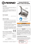
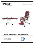
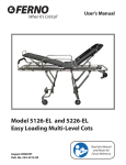
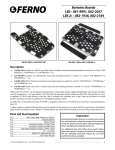
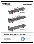
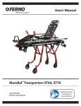
1
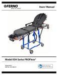
Dialysis Kickstand
Accessory Kits 082-2114 and 082-2116
Dialysis Kickstand
for Ferno Cot Models 35-P, 35-X, and POWERFlexx
Important - Using This Manual
Release Pedal
Mounting
Block
Instructions for installing the dialysis kickstand are on pages
1-9, and instructions for using and maintaining the kickstand
are on pages 10-16.
3/16 Inch
Allen Wrench
Once the kickstand has been installed, keep these instructions
with your cot users’ manual and include the usage portion in
your training program for cot operators.
Description of Kits
Dialysis Kickstand Kits 082-2114 and 082-2116 are designed to
adapt specified Ferno cots (Figure 1) for use on dialysis scales
too short to accommodate the cot wheel base.
The kickstand assemblies look very similar but are sized to fit
specific cot models. Before beginning assembly, check to make
sure you have the kit designated for your cot model, as follows:
082-2114
• Model 35-P PROFlex® Cot, all serial numbers
• POWERFlexx™ Cot, Serial Numbers Before 06 029075
082-2116
• 35-X PROFlexX® Cot, all serial numbers
• POWERFlexx™ Cot, Serial Numbers 06 029075 and
higher
Socket Head
Cap Screw (4)
Combined Installation and
Users’ Manual
No. 234-3373-00
Each kit contains a kickstand assembly, a 3/16 inch Allen wrench,
and an installation/users’ manual (all kits are represented by
Figure 2).
POWERFlexx Powered Cot
Mounting
Block
Kickstand
Figure 2 - Kit Components
Tools Required
3/16 inch Allen Wrench (supplied) ................................ 1
Tape measure ................................................................ 1
Marking pen .................................................................. 1
Parts Supplied
Kickstand Assembly ..................................................... 1
.250-20x1.000 Socket Head Cap Screw .......................... 4
3/16 inch Allen Wrench ................................................. 1
Installation and Users’ Manual No. 234-3373-00 ......... 1
Model 35-X PROFlexX
Model 35-P PROFlexx
Figure 1 - Ferno Cots Compatible with the Dialysis Kickstand
© Ferno-Washington, Inc. 234-3373-00 February 2007
1
Dialysis Kickstand
Model 35-P PROFlexx Cot®
1 - INSTALLING KIT 082-2114
ON A MODEL 35-P PROFLEXX COT
1.1 Installation
1.
For easiest access to the lower frame of the cot, raise the
cot to its highest position and tip it onto its foot-end
lifting frame.
Alternatively, you can raise the cot to its highest level
position and stand it on a workbench with all four
transport wheels on the work surface.
2.
For proper placement
of the kickstand, you
will need to remove a
portion of the
handgrip material
from the lower frame
of the cot (Figure 3).
Measure and mark
2-3/8 inches at the
end of the handgrip
nearest the head end
of the cot (Figure 4).
Handgrip
Material
Head End
Figure 5 - Attach the Patient’s Left Side Mount
Foot End
7.
Handgrip
Figure 3 - Handgrip
Check the mounting block placement by measuring from
the block to the edge of the wheel-shank mount as
shown in (Figure 6). The distance should measure 9-3/8
inches.
If your measurement is 9-3/8 to 9-1/2 inches, proceed to
Step 8. If it is not, continue with Step 7, below.
Edge of
Wheel Shank
Mount
Head End of Cot
2-3/8 inches
Mounting Block
Edge
9-3/8 inches
Figure 4 - Measure and Mark the Handgrip
3.
Use a utility knife to carefully cut through the handgrip
material around its entire circumference.
Then carefully slice the cut section horizontally and
remove the piece of handgrip material from the tube.
2
4.
Use the 3/16 inch Allen wrench to unthread the two bolts
from each kickstand mounting block.
5.
The mounting block with the release pedal will be
attached next to the handgrip. Position the two halves
of this mounting block around the frame tube and against
the cut end of the handgrip.
6.
Thread the two bolts an even distance into the mounting
block but do not tighten them completely (Figure 5).
Figure 6 - Check the Mounting Block Placement
If the measured distance is less than 9-3/8 inches, the
rubber bumper beneath the pedal may press against the
frame tube and prevent the pedal from functioning
properly. The bumper can touch the tube but should
not press against it.
If the bumper presses against the tube, adjust the
mounting block position as follows:
• Remove the mounting block, then remove enough
additional handgrip material to allow the rubber bumper
to touch the tube but not press against it. Reattach the
mounting block. Measure and record the new distance.
If the measured distance is greater than 9-1/2 inches,
remove the mounting block and attach it at the 9-3/8
inch point.
© Ferno-Washington, Inc. 234-3373-00 February 2007
Model 35-P PROFlexx Cot®
Dialysis Kickstand
8.
On the lower frame at the opposite side of the cot, extend
the tape measure from the wheel-shank mount toward
the foot end of the cot and mark the tube at 9-3/8 inches.
Head End of Cot
Note: If you adjusted the position of the first mounting block,
use the measurement you recorded after making the
adjustment.
9.
Place the two halves of the second mounting block
around the frame tube at the marked point.
10. Thread the two bolts an equal distance into the mounting
block but do not tighten them completely (Figure 7).
Figure 8 - Kickstand Engaged
3 inches
Figure 9 - Check the Floor-to-Wheel Distance
Figure 7 - Attaching the Patient’s Right Side Mount
11. Check the position of the second mounting block by
measuring again from the block to the edge of the wheelshank mount. This measurement should be the same as
the measurement for the first mounting block. If it is not,
adjust the position of the second mounting block.
4.
Raise and lock the kickstand.
• Lift the head end of the cot and push it away from you
a few inches to move the cot off the kickstand. Set the
cot down and move to one side of the kickstand.
• Use your toe to rotate the kickstand up until it locks
(Figure 10).
12. When both mounting blocks are positioned correctly,
finish tightening the bolts in both blocks.
1.2 Check the Installation
Follow the instructions in this subsection to confirm that the
kickstand is installed properly and functions properly.
1.
If the cot was tipped onto its foot end, tip it down onto
all four transport wheels and lower it to the highest level
position..
If the cot was standing on a workbench, move the cot to
the floor.
2.
Lower and engage the kickstand.
• To lower the kickstand, press down on the kickstand
pedal with your foot. The kickstand should rotate down
and rest against the floor.
• Move to the head end of the cot and lift it high enough
to allow the kickstand to rotate past the vertical and
engage (Figure 8).
3.
While the kickstand is engaged, check for its overall
proper positioning by measuring the distance from the
floor to the bottom of the raised wheel. The distance
should measure 3 inches (Figure 9).
© Ferno-Washington, Inc. 234-3373-00 February 2007
Figure 10 - Kickstand Raised and Locked
5.
If the measurement taken in Step 3 is correct and the
kickstand functions properly, it is ready for operators to
be trained in its use. See pages 10-16 for complete
operating instructions.
If the measurement is not correct, recheck all
measurements and make the required adjustments.
If the kickstand does not function properly but all
measured distances are correct, contact Ferno Customer
Relations (page 13).
3
POWERFlexx Cots Before S/N 06-02975
Dialysis Kickstand
2 - INSTALLING KIT 082-2114
ON A POWERFLEXX COT
(Serial Numbers Before 06 029075)
3.
2.1 Before You Begin
1.
Kit 082-2114 is designed for use with POWERFlexx
Powered Cots before serial number 06-029075. Check your
cot serial number to ensure that you will be using the
correct kit.
Note: The serial
number tag is
located under
the shock frame
on the crosstube
closest to the
control panel
(Figure 11).
• Hold the two halves of the block around the lower
frame tube and thread the bolts a little way into the block.
Leave the bolts loose enough to allow the block to slide
along the tube.
• Extend the measuring tape from the actuator mount
crosstube toward the head end of the cot and slide the
mounting block along the tube until the foot-end edge
of the block is at the 11-inch mark on the measuring tape
(Figure 13). Mark the tube at 11 inches.
Figure 11 - Serial Number
Location
Actuator Mount
Crosstube
2.2 Installation
1.
The kickstand will be
mounted on the lower
frame toward the cot’s
head end (Figure 12).
For easiest access to
the work area, raise
the cot to its highest
position, turn the cot
power switch OFF,
and gently tip the cot
onto its foot-end
lifting frame.
Head End of Cot
11 inches
Kickstand
Mounting Location
Figure 12 - Kickstand
Mounting Location
Alternatively, you can raise the cot to a high, but level,
position, turn the power switch OFF, and stand the cot
on all four transport wheels on a workbench.
Figure 13 - Measure To Find Mounting Point
4.
Important
Turn the cot power switch OFF before tipping
the cot onto its foot-end lifting frame, or before
placing it on a workbench.
2.
Have an assistant help you measure and mark the
mounting point for the mounting block on the patient’s
left side of the cot.
The mounting block with the release pedal will be
attached to the lower frame on the patient’s left side of
the cot.
5.
Position the
mounting block
at the 11-inch
mark and use
the supplied
Allen wrench to
tighten both
bolts evenly
but not yet
completely
(Figure 14).
Figure 14 - Attach First
Mounting Block
Measure to check that the block is mounted at the 11inch point. If it is not, adjust the position of the block.
Use the 3/16 inch Allen wrench supplied to remove the
two bolts from the mounting block.
4
© Ferno-Washington, Inc. 234-3373-00 February 2007
Dialysis Kickstand
6.
The
second
mounting block
will be attached
to the lower
frame on the
opposite side of
the cot. To
attach it (Figure
15) remove the
bolts from the
block and repeat
Steps 3-5.
POWERFlexx Cots Before S/N 06-02975
3.
While the kickstand is engaged, check for its overall
proper positioning by measuring the distance from the
floor to the bottom of the raised transport wheel. The
distance should measure 3/4 inch (Figure 17).
Figure 15 - Attach Second
Mounting Block
7.
Measure to check that the second block is positioned at
11 inches, and make any necessary adjustment.
8.
When both mounting blocks are positioned correctly,
finish tightening the bolts in both blocks.
3/4 inch
Figure 17 - Check the Floor-to-Wheel Distance
2.3 Check the Installation
4.
• Lift the head end of the cot and push it away from you
a few inches to move the cot off the kickstand. Set the
cot down and move to one side of the kickstand.
Follow the instructions in this subsection to confirm that the
kickstand is installed properly and functions properly.
1.
Raise and lock the kickstand.
If the cot was tipped onto its foot end lifting frame, tip it
down onto all four transport wheels and lower it to its
highest level position.
• Use your toe to rotate the kickstand up until it locks
(Figure 18).
If the cot was standing on a workbench, move the cot to
the floor.
2.
Lower and engage the kickstand.
• To lower the kickstand, press down on the kickstand
pedal with your foot. The kickstand should rotate down
and rest against the floor.
Head End of Cot
• Move to the head end of the cot and lift it high enough
to allow the kickstand to rotate past the vertical and
engage (Figure 16).
Head End of Cot
Figure 18 - Kickstand Raised and Locked
5.
Figure 16 - Kickstand Engaged
© Ferno-Washington, Inc. 234-3373-00 February 2007
If the measurement taken in Step 3 is correct and the
kickstand functions properly, it is ready for operators to
be trained in its use. See pages 10-16 for complete
operating instructions.
If the measurement taken in Step 3 is not correct, recheck
all measurements and make the required adjustments.
If the kickstand does not function properly but all
measured distances are correct, contact Ferno Customer
Relations (page 13).
5
Model 35-X ProflexX Cot
Dialysis Kickstand
3 - INSTALLING KIT 082-2116
ON A 35-X PROFLEXX COT
3.1 Installation
1.
The kickstand will be mounted near the head end of the
cot’s lower frame. For easiest access to the work area,
raise the cot to its highest position and tip it onto its
foot-end lifting frame.
Alternatively, you can raise the cot to a high but level
position and stand it on a workbench with all four
transport wheels on the work surface.
2.
You will need to
remove a portion of
the handgrip material
from the lower frame
of the cot (Figure 19).
Head End
Figure 21 - Attach the Patient’s Left Side Mount
7.
Foot End
Measure and mark
2-1/4 inches at the
head end of the
handgrip (Figure 20).
Handgrip
Check the mounting block placement by measuring from
the foot-end edge of the mounting block to the top edge
of the wheel fork (Figure 22). The distance should measure
15-3/8 inches.
If the measurement is 15-3/8 inches, proceed to Step 8. If
it is not, continue with Step 7, below.
Figure 19 - Hand Grip
2-
1/
n
4i
ch
ad
He
es
H
d
ea
En
f
do
Co
t
En
f
do
Co
t
s
he
nc
i
8
-3/
15
Figure 20 - Measure and Mark the Handgrip
Figure 22 - Check the Mounting Block Placement
6
3.
Use a utility knife to carefully cut through the handgrip
material around its entire circumference. Then, carefully
cut along each side of the scuff strip on the underside of
the tube and remove the handgrip material.
4.
Use the 3/16 inch Allen wrench to remove the two bolts
from each kickstand mounting block.
If the measured distance is less than 15-3/8 inches, the
rubber bumper beneath the pedal may press against the
frame tube and prevent the pedal from functioning
properly. The bumper can touch the tube but should
not press against it. If the bumper presses against the
tube, adjust the mounting block position as follows:
5.
The mounting block with the release pedal will be
attached next to the handgrip. Position the two halves
of this mounting block around the frame tube and against
the cut end of the handgrip.
• Remove the mounting block, then remove enough
additional handgrip material to allow the rubber bumper
to touch the tube but not press against it. Reattach the
mounting block. Measure and record the new distance.
6.
Thread the two bolts an even distance into the mounting
block but do not tighten them completely (Figure 21).
If the measured distance is greater than 15-3/8 inches,
remove the mounting block and attach it at 15-3/8 inches.
© Ferno-Washington, Inc. 234-3373-00 February 2007
Dialysis Kickstand
8.
Model 35-X ProflexX Cot
The second mounting block will be attached to the lower
frame on the opposite side of the cot.
Head End of Cot
• Hold the halves of the mounting block around the
frame tube and thread the bolts back into the block
loosely enough to slide the block along the tube.
• Extend the tape measure from the top edge of the
wheel fork toward the foot end of the cot and slide the
mounting block along the tube until the foot-end edge
of the block is at the 15-3/8 inch point on the tape
measure. Mark the tube at the 15-3/8 inch point.
Note: If you adjusted the position of the first mounting
block, use the measurement you recorded after making
the adjustment.
9.
Figure 24 - Kickstand Engaged
3.
While the kickstand is engaged, check for its overall
proper positioning by measuring the distance from the
floor to the bottom of the raised wheel. The distance
should measure 5/8 inch (Figure 25).
Position the mounting block at the marked point and
tighten the bolts, but not completely (Figure 23).
5/8 inch
Figure 25 - Check Floor-to-Wheel Distance
4.
Raise and lock the kickstand.
• Lift the head end of the cot and push it away from you
a few inches to move the cot off the kickstand. Set the
cot down and move to one side of the kickstand.
Figure 23 - Attach the Patient’s Right Side Mount
10. Re-measure the mounting positions of both blocks and
make any adjustments required before completely
tightening the bolts in both blocks.
• Use your toe to rotate the kickstand up until it locks
(Figure 26).
Head End of Cot
3.2 Check the Installation
Follow the instructions in this subsection to confirm that the
kickstand is installed properly and functions properly.
1.
If the cot was tipped onto its foot end, tip it down onto
all four transport wheels and lower it to its highest level
position..
If the cot was standing on a workbench, move the cot to
the floor.
2.
Lower and engage the kickstand.
• To lower the kickstand, press down on the kickstand
pedal with your foot. The kickstand should rotate
downward and rest against the floor.
• Move to the head end of the cot and lift it high enough
to allow the kickstand to rotate past the vertical and
engage (Figure 24).
© Ferno-Washington, Inc. 234-3373-00 February 2007
Figure 26 - Kickstand Raised and Locked
5.
If the measurement taken in Step 3 is correct and the
kickstand functions properly, it is ready for operators to
be trained in its use. See pages 10-16 for complete
operating instructions.
If the measurement is not correct, recheck all
measurements and make the required adjustments.
If the kickstand does not function properly but all
measured distances are correct, contact Ferno Customer
Relations (page 13).
7
Dialysis Kickstand
POWERFlexx Cots S/N 06-02975 and Higher
4 - INSTALLING KIT 082-2116
ON A POWERFLEXX COT
(Serial Number 06 029075 and Higher)
4.1 Before You Begin
1.
3.
Kit 082-2116 is designed for use with POWERFlexx
Powered Cots serial number 06-029075 and higher. Check
your cot serial number to ensure that you are using the
correct kit.
Note: The serial
number tag is
located under
the shock frame
on the crosstube
closest to the
control panel
(Figure 27).
• Hold the two halves of the block around the lower
frame tube and thread the bolts a little way into the block.
Leave the bolts loose enough to allow the block to slide
along the tube.
• Extend the measuring tape from the actuator mount
crosstube toward the head end of the cot and slide the
mounting block along the tube until the foot-end edge
of the block is at the 11-inch mark on the measuring tape.
Mark the tube at 11 inches (Figure 29).
Figure 27 - Serial Number
Location
Actuator Mount
Crosstube
4.2 Installation
1.
The kickstand will be
mounted on the lower
frame toward the cot’s
head end (Figure 28).
For easiest access to
the work area, raise
the cot to its highest
position, turn the cot
power switch OFF,
and gently tip the cot
onto its foot-end
lifting frame.
Head End of Cot
11 inches
Kickstand
Mounting Location
Figure 28 - Kickstand
Mounting Location
Alternatively, you can raise the cot to a high, but level,
position, turn the power switch OFF, and stand the cot
on all four transport wheels on a workbench.
Figure 29 - Measure To Find Mounting Point
4.
Important
Turn the cot power switch OFF before tipping
the cot onto its foot-end lifting frame, or before
placing it on the workbench.
2.
Have an assistant help you measure and mark the
mounting point for the mounting block on the patient’s
left side of the cot.
The mounting block with the release pedal will be
attached to the lower frame on the patient’s left side of
the cot.
5.
Position the
mounting block
at the 11-inch
mark and use
the supplied
Allen wrench to
tighten both
bolts evenly
but not yet
completely
(Figure 30).
Figure 30 - Attach First
Mounting Block
Measure to check that the block is mounted at the 11inch point. If it is not, adjust the position of the block.
Use the 3/16 inch Allen wrench supplied to remove the
two bolts from the mounting block.
8
© Ferno-Washington, Inc. 234-3373-00 February 2007
Dialysis Kickstand
6.
The
second
mounting block
will be attached
to the lower
frame on the
opposite side of
the cot. To
attach it (Figure
31) remove the
bolts from the
block and repeat
Steps 3-5.
POWERFlexx Cots S/N 06-02975 and Higher
3.
While the kickstand is engaged, check for its overall
proper positioning by measuring the distance from the
floor to the bottom of the raised transport wheel. The
distance should measure 3/4 inch (Figure 33).
Figure 31 - Attach Second
Mounting Block
7.
Measure to check that both blocks are positioned at 11
inches. Make any positioning adjustments needed.
8.
When both mounting blocks are positioned correctly,
finish tightening the bolts in both blocks.
3/4 inch
Figure 33 - Check the Floor-to-Wheel Distance
4.3 Check the Installation
4.
• Lift the head end of the cot and push it away from you
a few inches to move the cot off the kickstand. Set the
cot down and move to one side of the kickstand.
Follow the instructions in this subsection to confirm that the
kickstand is installed properly and functions properly.
1.
Raise and lock the kickstand.
If the cot was tipped onto its foot end lifting frame, tip it
down onto all four transport wheels and lower the cot to
its highest level position.
• Use your toe to rotate the kickstand up until it locks
(Figure 34).
If the cot was standing on a workbench, move the cot to
the floor.
2.
Lower and engage the kickstand.
Head End of Cot
• To lower the kickstand, press down on the kickstand
pedal with your foot. The kickstand should rotate
downward and rest against the floor.
• Move to the head end of the cot and lift it high enough
to allow the kickstand to rotate past the vertical and
engage (Figure 32).
Head End of Cot
Figure 34 - Kickstand Raised and Locked
5.
If the measurement taken in Step 3 is correct and the
kickstand functions properly, it is ready for operators to
be trained in its use. See pages 10-16 for complete
operating instructions.
If the measurement taken in Step 3 is not correct, recheck
all measurements and make the required adjustments.
Figure 32 - Kickstand Engaged
© Ferno-Washington, Inc. 234-3373-00 February 2007
If the kickstand does not function properly but all
measured distances are correct, contact Ferno Customer
Relations (page 13).
9
Using the Kickstand
Dialysis Kickstand
5 - USING THE KICKSTAND
5.1 Safety Information
5.2 Operator Skills and Training
WARNING
notices such as the one below indicate a potentially hazardous
situation which, if not avoided, could result in injury or death.
! WARNING
Untrained operators can cause injury or be
injured. Permit only trained personnel to
operate the kickstand.
IMPORTANT
notices such as the one below emphasize important usage or
maintenance information.
Important
Turn the cot power switch OFF before tipping
the cot onto its foot-end lifting frame, or before
placing it on the workbench.
SKILLS
Operators using the kickstand need:
a working knowledge of patient-handling procedures.
the ability to assist the patient.
a complete understanding of the procedures described
in this manual and in the cot users’ manual.
TRAINING
Trainees need to:
follow a training program designed by their training
officer.
read this manual. For additional free manuals, contact
your Ferno distributor or Ferno Customer Relations (page
13).
practice using the kickstand before using it in regular
service.
be tested on their understanding of the kickstand’s use.
record their training information.
BLOODBORNE DISEASE NOTICE
! WARNING
To reduce the risk of exposure to bloodborne diseases such as
HIV-1 and hepatitis when using the kickstand, follow the
disinfecting and cleaning instructions in this manual.
Untrained operators can cause injury or be
injured. Permit only trained personnel to
operate the kickstand.
USERS’ MANUALS
Read the users’ section of the dialysis kickstand manual, plus
the users’ manual for the cot on which the kickstand has been
installed.
5.3 About the Kickstand
For additional, free users’ manual, contact your Ferno
distributor or Ferno Customer Relations, page 13.
The dialysis kickstand (called the kickstand in this manual) is a
device designed to adapt specified Ferno cots for use on dialysis
scales that are too short to accommodate the cot wheel base.
Read the users’ manuals for
the dialysis kickstand and the
cot on which the kickstand
has been installed.
DESCRIPTION
The dialysis kickstand is intended for professional use only.
Using the kickstand requires a minimum of two trained operators
at all times.
! WARNING
Improper use of the kickstand can cause
injury. Use the kickstand only for the
purpose described in this manual.
10
© Ferno-Washington, Inc. 234-3373-00 February 2007
Using the Kickstand
Dialysis Kickstand
KICKSTAND COMPONENTS
The kickstand mounts to both sides of the lower frame of the
cot (Figure 35). A release pedal with a spring mechanism allows
the kickstand to rotate down for lowering and engagement.
The kickstand locks in the raised position when not in use.
Release
Pedal
5.5 Engaging the Kickstand
When the kickstand is engaged, it raises the head end of the
cot until the wheels are off the floor. This transfers the cot and
patient weight to the foot end of the cot and the kickstand.
Always park the cot with the foot-end wheels on the scale and
the head-end wheels on the floor (Figure 36).
Cot
Head
End
Kickstand
Combined
installation and users’ manual,
Pub. # 234-3373-00
Figure 35 - Kickstand Components
Foot
End
Head-End
Wheels
on
Kickstand
Floor
Scale
Foot-End
Wheels
on
Scale
Figure 36 - Parking the Cot on the Scale
5.4 General Guidelines for Use
•
Using the kickstand requires a minimum of two trained
operators at all times. Operators work together,
communicate with each other, and operate the kickstand
using coordinated movements.
•
Lift only the weight you can safely handle. Use additional
help when working with heavy loads (patient and
equipment).
•
Stay with the cot and patient when the patient is on the
cot. Be especially alert when the kickstand is in use.
•
Use patient restraints.
! WARNING
Improper operation can cause injury.
Operate the kickstand only as described in
this manual.
Note: Use a minimum of two trained operators at all times.
1.
Both Operators: Roll the cot to the edge of the dialysis
scale and stop to check that the cot is in a rolling (level)
position and that patient restraints are fastened.
2.
Both Operators: Roll the cot onto the scale and park it
with the foot-end wheels on the scale and the head-end
wheels on the floor.
3.
Assisting Operator: Stand at the foot end of the cot and
prepare to grasp the main frame with an underhand grip
(palms up).
4.
Pedal/Lifting Operator: Stand beside the cot and use
your toe to press down on the release pedal to unlock
the kickstand (Figure 37). The kickstand will rotate down
until it rests against the scale.
Move to the head end of the cot and prepare to grasp
the main frame with an underhand grip (palms up).
An unrestrained patient can fall off the cot
and be injured. Use restraints to secure the
patient on the cot.
An unattended cot with a patient on it can
be moved or bumped by unauthorized
personnel and cause injury. Stay with the cot
when the patient is on it and be especially
alert while the kickstand is engaged.
Figure 37 - Lowering Kickstand
© Ferno-Washington, Inc. 234-3373-00 February 2007
11
Using the Kickstand, Maintenance
5.
Both Operators: The pedal/lifting operator grasps the
cot main frame and lifts the head end of the cot high
enough to allow the kickstand to rotate past the vertical
and engage (Figure 38).
The assisting operator grasps the main frame to ensure
stability as the cot is lifted.
Dialysis Kickstand
6 - MAINTENANCE
6.1 Maintenance Schedule
Disinfect, clean and inspect the kickstand using the same
products and schedule used for the cot. The kickstand does
not require lubrication.
! WARNING
Improper maintenance can cause injury.
Maintain the kickstand only as described
in this manual.
Figure 38 - Kickstand Engaged
6.
Both Operators: The pedal/lifting operator gently lowers
the cot until its weight rests fully on the scale.
The assisting operator grasps the main frame to ensure
stability as the cot is lowered.
5.6 Raising the Kickstand
1.
Both Operators: Assume your positions at the head
and foot ends of the cot and grasp the main frame.
2.
Both Operators: Ensure that the cot remains stable
during this step.
Pedal/Lifting Operator: Throughout this step, hold
and control the weight of the cot and move slowly in
order to move the cot off the kickstand smoothly.
Lift the head end of the cot a few inches and control its
weight as you gently push the cot away from you to
move it off the kickstand. Lower the wheels to the scale.
Important
Lowering the cot abruptly can jolt the patient and
cause discomfort. Hold and control the weight
of the cot as you move the cot off the kickstand.
3.
12
When using maintenance products, follow the manufacturers’
instructions and read the material safety data sheets.
To disinfect: Apply disinfectant to all surfaces according to
the disinfectant manufacturer’s directions for application and
contact time.
To clean: Hand wash the all parts of the kickstand with warm
water and a mild detergent. Use a brush with stiff bristles (but
not a wire brush) to remove stains. Rinse with warm, clear
water. Dry the kickstand with a towel or allow it to air-dry.
6.3 Inspecting the Kickstand
Have your service’s equipment maintenance personnel inspect
the kickstand. Follow the checklist below and work the
kickstand through all its functions as described in this manual.
If the inspection shows damage or excessive wear, remove the
kickstand from service until repair is made (see Parts and
Service, pages 14 and 15).
INSPECTION CHECKLIST
Are all components present?
Is the kickstand free of excessive wear?
Pedal/Lifting
Operator: Move to
the side of the cot
and use your toe to
rotate the kickstand
up until it locks in the
raised
position
(Figure 39).
The cot can now be
rolled off the scale.
6.2 Disinfecting and Cleaning
the Kickstand
Are all screws, nuts, bolts and roll pins securely in
place?
Do all moving parts function smoothly and properly?
Figure 39 - Raising the
Kickstand
© Ferno-Washington, Inc. 234-3373-00 February 2007
Customer Relations , Warranty
Dialysis Kickstand
7 - FERNO
CUSTOMER RELATIONS
Customer service and product support are important aspects
of each Ferno product.
For assistance, please contact Ferno Customer Relations:
Canada and the U.S.A.
Telephone (Toll-free) ..................................... 1.877.733.0911
Telephone ...................................................... 1.937.382.1451
Fax (Toll-free) ................................................. 1.888.388.1349
Fax .................................................................. 1.937.382.1191
Internet ........................................................ www.ferno.com
For assistance or information, please contact your Ferno
distributor. If you do not have a Ferno distributor, please
contact Ferno Customer Relations:
Telephone .............................................. +1.937.382.1451
Fax .......................................................... +1.937.382.6569
Internet ................................................... www.ferno.com
8- LIMITED WARRANTY
STATEMENT
The products sold by Ferno are covered by a limited warranty.
The actual terms and conditions of the limited warranty, and
the limitations of liability and disclaimers, are available upon
request by calling 1.800.733.3766 or 1.937.382.1451.
European Representative
Ferno (UK) Limited, Stubs Beck Lane, Cleckheaton
West Yorkshire BD19 4TZ, United Kingdom
Telephone
+44 (0) 1274 851999
Fax
+44 (0) 1274 851111
Internet
www.ferno.co.uk
234-3468-00
© Copyright Ferno-Washington, Inc. All Rights Reserved.
Ferno-Washington, Inc.
70 Weil Way
Wilmington, OH 45177-9371 U.S.A.
Telephone (Toll Free) ..................................... 1.877.733.0911
Telephone .................................................... +1.937.382.1451
Fax (Toll Free) ............................................... 1.888.388.1349
Fax ............................................................... +1.937.382.1191
Internet ........................................................ www.ferno.com
© Ferno-Washington, Inc. 234-3373-00 February 2007
13
Dialysis Kickstand
Parts and Service
9 - PARTS AND SERVICE
! WARNING
REPAIRS AND PARTS
EMSAR® is the only organization authorized by Ferno to
manage, service, and repair Ferno products.
Telephone (Toll-free) ............................ 1.800.73.EMSAR
Telephone (Worldwide) ............................ 1.937.383.1052
Fax (Worldwide) ....................................... 1.937.383.1051
Internet .............................................. www.EMSAR.com
Modifying the kickstand can cause injury
and damage. Use the kickstand only as
designed by Ferno.
! WARNING
Improper parts and service can cause
injury. Use only Ferno parts and Fernoapproved service on the kickstand.
9.1 Parts List
Kit #
1
2
3
3
4
5
6
7
14
Description
Part #1
Mount, Right w/Hardware ..................... 190-1672
Torsion Spring w/Hardware .................. 190-1673
Kickstand w/Hardware ......................... 190-1674
Kickstand w/Hardware ......................... 190-1675
Lock Plate w/Hardware ........................ 190-1677
Lock Pedal w/Hardware ....................... 190-1678
Compression Spring w/Hardware ......... 190-1679
Mount, Left w/Hardware ...................... 190-1680
Cot Models
......................35-P, 35-X, All POWERFlexx serial numbers
......................35-P, 35-X, All POWERFlexx serial numbers
....... 35-P, POWERFlexx serial numbers before 06 029075
... 35-X, POWERFlexx serial numbers 06 029075 & higher
......................35-P, 35-X, All POWERFlexx serial numbers
......................35-P, 35-X, All POWERFlexx serial numbers
......................35-P, 35-X, All POWERFlexx serial numbers
......................35-P, 35-X, All POWERFlexx serial numbers
© Ferno-Washington, Inc. 234-3373-00 February 2007
Dialysis Kickstand
Parts and Service
9.2 Parts Diagram
The numbers on this diagram correspond to the kit numbers in
the parts list on page 14.
1
5
3
5
1
2
7
2
6
3
5
7
3
4
3
4
7
7
35-P and
3 POWERFlex before serial
numbers 06 029075
5
3
© Ferno-Washington, Inc. 234-3373-00 February 2007
3 35-X and
POWERFlex serial number
06 029075 and higher
15