1
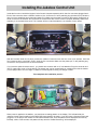
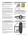
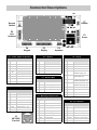
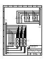
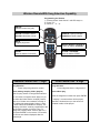
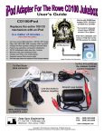
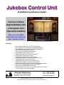
Jukebox Control Unit
Installation and Users Guide
Convert a Rowe
Digital Wallbox Into
a Complete Coin
Operated Jukebox
Now you can make
selections directly from
your remote control
Works with all Rowe WRE and WRF Digital Wallbox Selectors
Features
•
•
•
•
•
•
•
•
•
•
•
•
•
•
•
•
•
•
Easy control board replacement, takes only seconds to install
Uses Compact Flash Card technology for 100% Solid-State reliability
Plays all MPEG layer-III encodings , fixed and VBR, up to 320 kbits/s
Super fast song changes between selections
Shows credits, song popularity & selection playing
Programmable coin ratios or set to free play
Programmable autoplay: off, 1-30 minutes or continuous
Song selections have priority over autoplay
Programmable autoplay start & end range, 0xx to 9xx
Programmable selection range: 100-299 or 000-999 (1,000 songs)
Programmable retain or erase credits at power up
Programmable retain or erase selected songs at power up
Integrated power amplifier, can also drive external speakers
Works with existing wallbox power supply (requires Radio Shack transformer)
Full range volume control adjustment using front panel buttons
Cancel play by holding Reset button for 8-seconds
Wireless remote for volume, pause, cancel, autoplay on/off and song selections
"Line -out" cable to hook up your own amplifier
Data Sync Engineering
P.O. Box 539, 2 Footbridge Lane
Blairstown, New Jersey 07825
TEL: (908) 362-6299
FAX: (908) 362-5889
www.datasynceng.com
Copyright © 2006 Data Sync Engineering. All Rights Reserved.
Designated trademarks and brands are the property of their respective owners.
Installing the Jukebox Control Unit
Inside the front door, behind the keypad, is the Control Computer assembly which has five connectors plugged into it.
Each of the connectors have a different number of pins. Connector P1 has a polarizing key (blocked off pin) while the
other four have polarizing pegs (protruding plastic pin). Make sure the power is turned off then gently unplug each of
these connectors. Remove the four screws at the corners then take out the Control Computer assembly. Behind the
assembly is an insulation base card. This insulator will be re-used beneath the new Jukebox Control board.
With the insulation base card in place, position the Jukebox Control Unit over the four corner nylon spacers. Insert the
four screws but don’t over tighten. Plug in each the five connectors. Make sure the plastic pin, on the polarizing peg
connectors, line up with the hole in the circuit board.
If you have the optional remote control, you should have a sensor with a 12” wire attached. Plug the connector end
into P7 (upper right corner of circuit board). The sensor part can be located inside or outside the box but the bubble
(or lens part) must be in line-of-sight or visible to infrared signals bouncing off ceilings or walls.
This completes the installation process.
When power is applied to the wallbox, you should see a rotating pattern on the display. This indicates that the
Jukebox Control board is waiting for the MP3-DSP player board to be ready. If you don’t have a Compact Flash card
plugged in or the player was not able to find folders with MP3 files, then this pattern will be displayed continuously.
Normally, within a few seconds, this pattern will stop and the “Credits Remaining” will be displayed.
Checking the Compact Flash Card Format
Before using your Compact Flash card, check the
file system. It will either be FAT or FAT32.
Plug in your USB Compact Flash reader/writer.
After a few moments, the computer should
indicate that the flash card is ready.
Click My Computer
Right click on the Compact Flash drive letter
Then click on Properties
The File system should be FAT32
If it isn’t, then re-format the Compact Flash card.
Click My Computer
Right click on the Compact Flash drive letter
Then click on Format
Select the FAT32 File system then click Start
When the WARNING message appears …
Click OK
Creating Folders / Drag & Drop your MP3 Files
Songs are selected using a 3-digit entry. These digits are directly related to the folders & files stored on the Compact
Flash card. The first digit (or hundreds digit) selects the folder number. The next two digits select a file within that
folder. By default, only two folders are used, 01 & 02, which are selected by 1xx & 2xx respectively. Each of these
folders contain 100 song files numbered 00-99. If you choose to increase the selection range (service mode,
parameter C) then you will need to create additional folders. You can have up to ten folders which are selected by
1xx through 9xx & 0xx.
To create a new folder …
Double click on the Compact Flash drive letter
Then click File | New | Folder
You should see a New Folder name.
Change the name …
The first two letters are numeric digits that identify
the folder position. Typically, this would be 01 & 02.
You will need to create additional folders if you
chose to increase the selection range. Any letters
following these two digits are ignored and can be
any text you choose.
As shown above, numbered folders are
selected from the first digit entry. Here, MP3
song names must also be numbered and are
selected from the second and third digit entry.
Using Windows Explorer, you can drag & drop
selected song files to your Compact Flash card.
Select the disk and folder for your source of
MP3 song files, place your mouse over the
song then hold down the left mouse button and
drag it to your Compact Flash folder.
If you need to change or add the selection
position number of a song, place the mouse
over the song then right click and select
Rename.
MP3 song files can be changed at any time,
simply delete the old file and insert the new
one.
Service Mode
Popular Key
Service mode is entered when the slide-switch is moved
to the SERVICE position. Upon initial entry, the keypad
and coin signals are checked. If any signal is stuck on,
E07 or E08 will be displayed until the problem is
resolved.
As songs are selected, a popularity list is created. This
list only applies to songs within the 100 to 299 selection
range. When the POPULAR key is pressed, the Most
Popular song number is displayed. The song is NOT
forced into the play list allowing the user to make the
decision. Pressing the POPULAR key again brings up
the next popular selection. This is repeated until the end
of the list is reached by displaying “- - -”. Pressing
RESET at any time restarts the popularity list back to
the first Most Popular. Unplayed songs are not
displayed.
There are 18 parameter steps. The first step, parameter
#0, is used to test or identify the coin switch number for
accepted coins. Pressing the POPULAR key will display
the error counter.
You can step through each of the parameter positions
by pressing the RESET key. All parameter values,
except #0, can be changed using the “1” or “6” key. The
“1” key increases the value and the “6” key decreases
the value. All setup values are stored in EEPROM
memory and are not affected by power loss.
Pressing and holding the RESET key for about 8
seconds while in service mode, resets all parameters
back to the factory default. P00 will be displayed as an
affirmative response. Press RESET to continue. See
“Service Mode Programming” for a description of each
parameter.
During normal operation, selections, credits, errors and
the autoplay sequencer are stored in memory to provide
statistical information, the next autoplay selection and to
optionally retain credits and selections during power
failure. To erase this memory and reset the autoplay
sequencer, press and hold the POPULAR key for about
8 seconds while in service mode. P01 will be displayed
as an affirmative response. Press RESET to continue.
If you make any changes to an autoplay parameter, you
will need to erase memory for the autoplay sequencer
change to take effect.
Credit Pricing or Free Play
You can provide different credit amounts based on the
accumulated coins before a selection is made. The table
below provides typical coin ratio examples with service
mode parameter values.
Credit Levels
25¢ 50¢ 75¢ $1
1
2
3
5
1
3
5
7
1
2
4
8
1
2
5 10
Free Play
Service Parameter Values
#6 #7 #8 #9 #A #b
0
0
1 1
1
2
0
0
1 2
2
2
0
0
1 1
2
4
0
0
1 1
3
5
31 x
x x
x
x
Shaded area = factory default
x = don’t care
The popularity list is erased by entering service mode
and holding the POPULAR key until P01 is displayed.
The POPULAR key has an alternate function that allows
you to adjust the volume level. While a song is playing,
hold the POPULAR key until the “Aud” message
appears. Press the “1” key to increase the volume or the
“6” key to decrease the volume. Automatic exit will occur
within 8 seconds of no activity or press RESET.
Reset Key
Pressing the RESET key at any time brings up the
“Selections Remaining” count. The RESET key will also
cancel the selection being made if the first or second
digit was entered by mistake. The RESET key has no
effect if all three digits were entered.
The RESET key has an alternate function that allows
you to cancel the song that is playing. Hold the RESET
key until the song is canceled (about 8 seconds).
Autoplay
The autoplay feature has three modes of operation; (1)
no autoplay, (2) timed autoplay and (3) continuous
autoplay. In timed autoplay, you can set from 1 to 30
minutes of no activity before a song is played. In
continuous autoplay, songs are played one aft er another
unless a selection is made. After the end of the current
playing song, all of the selected songs are played, then
returns back to autoplay.
Autoplay sequentially plays songs from the programmed
Start Folder until it reaches the end of the programmed
End Folder which causes a restart to the Start Folder.
You can program autoplay to play songs from a single
folder or multiple folders. You can even create totally
separate folders just for autoplay selections, such as for
background play. You don’t need to have all 100 songs
in a folder, autoplay will skip over songs not found.
Song selections are made using a 3-digit number. If no
credits are available, or not in Free Play, the key is
ignored and the “Selections Remaining” will be
displayed.
Compact Flash Card Capacities
USB 2.0
Reader/Writer
CF Card
Making Selections
If the first digit is not within the allowable range, it is
ignored (service mode parameter “C”).
If you change your mind after the first or second digit
entry, you can start over by pressing RESET. If all three
digits have been entered, then RESET has no effect.
As digits are entered, the display will show “Selection
Being Made”. After all three digits are entered, the song
play will begin immediately or if another song is
currently playing, the new selection will be stored in
memory. If the same song is already in memory, waiting
to be played, then the new selection will be discarded to
eliminate duplicates.
The “waiting to play” memory can store up to 126 song
selections. If the memory if full, the new selection is
ignored and the credit will not be taken.
Song capacities using 128 Kbps (near CD quality)
1GB
2GB
4GB
250 songs
500 songs
1,000 songs
Wallbox Power Supply
The wallbox needs a 25-30 volt A.C. power transformer
to operate. You can purchase this from Radio Shack.
Wire “A” connects to wallbox terminal marked “Power
Com.“ and wire “B” goes to the terminal marked “A.C.
Power”.
A
YEL
FUSE
After a selection is made, the display will continue to
show “Selection Being Made” for about 2 seconds,
switch to “Credits Remaining” for about 5 seconds then
finally “Selection Playing”. Pressing RESET will bring up
“Credits Remaining” then back to “Selection Playing”.
1-Amp
The integrated power amplifier is capable of delivering
3 watts per channel of continuous average power into a
4 ohm load at 0.2% THD+N.
Transformer
The speaker signals can be taken from connector P2, or
if you insert jumpers W2 and W3, the speaker signals
will be available at the wallbox terminal strip as L. Ch.,
Com., and R. Ch.
A “line-out” cable is available that allows you to hook up
to your own external amplifier. The cable plugs into J3
on the MP3-DSP player board and has a pair of RCA
male connectors at the end.
B
25VAC
2 Amps
Wireless Remote Control
Connect to P7
The remote sensor
“eye” can be placed
at the right bottom
corner edge, inside
the title page glass.
The internal wallbox speakers are 45 ohms impedance
with a frequency response of 150–10,000 Hz. They
provide a power output of about 0.18W / speaker.
For a better frequency response at a reasonable volume
level, you can add a pair of external 8 ohm speakers
boosting the power output to 2 Watts.
Not used
apply tape
YEL
Radio Shack 273-1512B
or equiv
Amplifier & Speakers
BLK
Remote Set Up
Press & hold Code
Search until the LED
stays on.
The bubble (or lens
part) must be in
line-of-sight of the
remote transmitter
or visible to infrared
signals bouncing off
ceilings or walls.
Release Code Search
Press "TV" then
Enter
039
LED turns off after
code is entered.
Remote button details are at the end of this manual
Service Mode Programming
Coin switch test/identifier. Error count display.
Identifies the coin switch number (1 to 5) for each accepted coin type
or press the Popular key to view the error count.
Coin switch #1 monetary value (expressed in nickel units).
This coin switch is usually the 5¢ chute.
Enter zero if this coin switch is not used or you if don’t want to accept this coin type.
Coin switch #2 monetary value (expressed in nickel units).
This coin switch is usually the 10¢ chute.
Enter zero if this coin switch is not used or you if don’t want to accept this coin type.
Coin switch #3 monetary value (expressed in nickel units).
This coin switch is usually the 25¢ chute.
Enter zero if this coin switch is not used or you if don’t want to accept this coin type.
Coin switch #4 monetary value (expressed in nickel units).
This coin switch is usually the 50¢ chute.
Enter zero if this coin switch is not used or you if don’t want to accept this coin type.
Coin switch #5 monetary value (expressed in nickel units).
This coin switch is usually the $1 value, in most cases, it is not us ed.
Enter zero if this coin switch is not used or you if don’t want to accept this coin type.
Credit to add when 1 unit is reached (5¢). Also used to set free-play mode.
Credit ratios are established using accumulated unit steps. Unit count is reset when a selection is made.
Set this value to 31 to enable free-play operation.
Credit to add when 2 units are reached (10¢).
Credit ratios are established using accumulated unit steps.
Unit count is reset when a selection is made.
Credit to add when 5 units are reached (25¢).
Credit ratios are established using accumulated unit steps.
Unit count is reset when a selection is made.
Credit to add when 10 units are reached (50¢).
Credit ratios are established using accumulated unit steps.
Unit count is reset when a selection is made.
Credit to add when 15 units are reached (75¢).
Credit ratios are established using accumulated unit steps.
Unit count is reset when a selection is made.
Credit to add when 20 units are reached ($1).
Credit ratios are established using accumulated unit steps.
The unit count is reset when it reaches this step.
Highest selection digit allowed.
2 allows 100-299, 3 allows 100-399 and so on. 0 allows 000-999.
Of the 3-digit entry, the first digit (or highest digit) represents folder numbers 01 through 09 and 00.
Credits after power failure.
0= Erase, 1= Retain
Selections after power failure.
0= Erase, 1= Retain
Autoplay time in minutes.
1 to 30 minutes, 0= No autoplay, 31= Continuous autoplay
Song selections have priority over autoplay
Start Folder for autoplay selections.
Song playing starts at the beginning of this folder whenever an erase memory function is performed
or the last song in the End Folder is played.
End Folder for autoplay selections.
When the last song in this folder is played, autoplay will restart at the beginning of the Start Folder.
Start & End Folders can be separate from user selection folders (100-299), such as 300-999.
Error Codes
Memory is corrupted or is not initialized.
To initialize memory,
Set the switch to service mode then press and hold the Reset key until P00 is displayed.
Memory error.
Replace the Jukebox Control Unit board or replace memory chip U4.
Not a valid song request command.
Communication problem between the JCU board and MP3 player board.
Press Reset and see if the error re-appears (could be a power supply problem).
MP3 player timeout.
The MP3 player took too long to start playing.
Press Reset and see if the error re-appears (could be a compact flash card problem).
The requested song was not found.
Check the folder & file number to see if the song exists.
This error does not require a reset operation.
MP3 player did not respond with a command acknowledgment.
Communication problem between the JCU board and MP3 player board.
Press Reset and see if the error re-appears (could be a power supply problem).
Key pad key is stuck on (checked when entering service mode).
To confirm key pad problem,
Unplug connector P4, turn the unit on and see if the error re-appears .
Coin switch is stuck on (checked when entering service mode).
To confirm coin switch problem,
Unplug connector P5, turn the unit on and see if the error re-appears .
Service mode programming has been defaulted to factory settings.
Affirmative response to entering service mode and holding the Reset key for about 8-seconds.
Statistical memory has been erased.
Resets autoplay start, clears error count, credits and song selections.
Affirmative response to entering service mode and holding the Popular key for about 8-seconds.
Connector Descriptions
W1
4321
SERVICE
Service
Switch
NORMAL
9 8 7 6 5 4 3 2 1
J3
7 6 5 4 3 2 1
P5
Coin
Switches
8 7 6 5 4 3 2 1
12 11 10 9 8 7 6 5 4 3 2 1
5 4 3 2 1
P4
P3
P2
Keypad
Display
Speakers
P1 – Power & External Speakers
Pin
Name
1
P7
Remote
Description
W3
P2 – Speakers
Pin
Name
Not used
1
Peg
2
Not used
2
RSPK
3
Not used
3
LSPK
4
+13VDC
4
SCOM
5
Key
5
Not used
6
Ground
7
RSPK
Right speaker if “W2” inserted
8
LSPK
Left speaker if “W3” inserted
9
SCOM
Speaker common
Power supply input, +13 to 15V
W2
Description
P1
Power
P3 – Display
Pin
Name
Description
1
Peg
Right speaker
2
SEGC
Display segment “c”
Left speaker
3
SEGA
Display segment “a”
Speaker common
4
SEGG
Display segment “g”
5
SEGB
Display segment “b”
“Selection Playing” LED
6
SEGE
Display segment “e”
“Most Popular” LED
7
SEGF
Display segment “f”
“Selection Being Made” LED
8
SEGD
Display segment “d”
“Selections Remaining” LED
Power supply common
P4 – Keypad
Description
P7 – Remote / Mute
Pin
Name
Description
1
IRIN
2
PGND
Power supply ground
3
5VDC
+5VDC output
9
LED
LEDs +V source driver
4
MUTE
Mute signal out, active high
10
DIG1
Digit 1 +V source driver
IR signal input
Pin
Name
1
Peg
11
DIG2
Digit 2 +V source driver
2
ROW3
Row keys MP, 1 & 7
12
DIG3
Digit 3 +V source driver
3
ROW4
Row keys R, 0 & 6
4
ROW1
Row keys 5, 3 & 9
5
ROW2
Row keys 4, 2 & 8
6
COL3
Column keys 9, 8, 7 & 6
7
COL2
Column keys 3, 2, 1 & 0
8
COL1
Column keys 5, 4, MP & R
J3 – MP3 Player DIN Connector
Pin
Name
Description
1
RCH
Right channel line level output
2
LCH
Left channel line level output
Pin
Name
3
5VDC
+5VDC output
1
Peg
4
AGND
Analog ground
2
CSW4
Coin switch #4 (50¢)
5
PGND
Power supply ground
3
CSW3
Coin switch #3 (25¢)
P5 – Coin Switches
Description
6
+VIN
Power supply input, +12V
4
CSW1
Coin switch #1 (5¢)
J3
7
SOUT
Serial data output
5
CSW2
Coin switch #2 (10¢)
MP3-DSP
"Line-Out"
8
IRIN
IR signal input
6
CSCAN
9
SIN
Serial data input
7
CSW5
Coin scan +V source driver
Coin switch #5 ($1)
1
2
3
4
5
6
7
8
A
Peg
1
2
3
4
B
5
MP
R
5
4
1
0
3
2
7
6
9
8
Display
C
6
P3
7
8
1
Peg
2
P4
Keypad
3
D
4
5
6
7
d
f
e
b
g
a
c
8
2
7
13
11
1
10
d
f
e
b
g
a
c
a
a
a
MAN72A or equiv
b
f
b
f
g
c
(Common Anode)
g
c
e
d
b
f
g
e
LEDs
c
e
d
d
Data Sync Engineering
14
9
3
14
9
3
14
9
9
3
G
8
2
7
13
11
1
10
d
f
e
b
g
a
c
8
2
7
13
11
1
10
Selections Remaining
Selection Being Made
F
Most Popular
8
Selection Playing
E
P.O. Box 539, Footbridge Lane, Building 3
Blairstown, NJ 07825 (908) 362-6299
10
1st Digit
JCU Display & Keypad
11
2nd Digit
H
12
1N4001
3rd Digit
Date
05/25/2006
Sheet
Engineer
of
Doc. File
jcudk.sch
Rev.
A
Wireless Remote With Song Selection Capability
Programming the Remote
1) Press and hold "Code Search" until LED stays on
2) Press "TV"
3) Press "0" "3" "9"
ON-OFF
Cancels current song play
VOL UP = Increase volume
VOL DN = Decrease volume
MUTE
Toggles play/pause
ENTER
Same as wallbox POPULAR
Jukebox Control Unit - 3 Digit
CHAN UP = Always autoplay
CHAN DN = Timed autoplay
Numeric buttons 0 through 9
Same as wallbox NUMBERS
TV-VCR or ANTENNA
Same as wallbox RESET
CDW Control Unit - 4 Digit
Song Selection
Press 3-digit song selection number
Song Selection
Press 2-digit disc # then 2-digit track #
Select starting autoplay folder (playlist)
Great for party events or background ambiance.
Select album play
Press the 2-digit disc number then press ENTER.
The JCU does not support album plays but you
can select the folder that the "autoplay feature"
plays from. Folders are numbered 0 through 9.
The wallbox title pages display folders 1 and 2.
All other folders are available for autoplay. The
"autoplay end folder" must be programmed to the
highest folder number you will be using. To
change the autoplay folder: Press a digit 0 to 9
then press ENTER on the remote. If successful,
you will see two dashes displayed after the
entered digit.
If "freeplay", the entire album will be played,
otherwise, all selections up to the amount of
available credits, will be played.