1
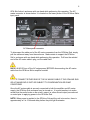
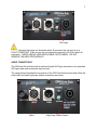
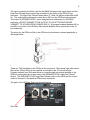
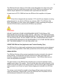
1
On Point Audio, Inc.
OPALine SUB USER MANUAL
The exclamation point within an equilateral triangle is intended to alert the user to
the presence of important operation and maintenance instructions.
The lightening flash with arrowhead symbol within an equilateral triangle is
intended to alert the user to the presence of un-insulated “dangerous voltage”
within the product’s enclosure that may be of sufficient magnitude to constitute a
risk of electric shock to people.
2
The On Point Audio OPALine Sub was designed to provide very high performance
sound reinforcement and very high-output, low-frequency response. The OPALine Sub
is an active, dual-channel design that routes one channel of the amplifier output to the
18” woofer and the second channel to a high level, high pass output. The OPALine Sub
was designed for use in portable and fixed installation indoor environments such as
night clubs, churches, meeting halls and general live performance applications. The
OPALine Sub features an 18 -inch (457 mm) diameter woofer, Class-D amplifier, high
order analog filter processing and enclosure design that provides very high acoustic
output with extended low frequency response. The system was designed to work in
conjunction with the On Point Audio OPALine system. The OPALine Sub Active also
features professional-grade locking casters for easy system positioning and movement.
Specifications
Frequency Response:
Coverage Pattern:
Input/Thru:
Power:
Peak - Total System:
Continuous- Total System:
Subwoofer Peak Power
Subwoofer Continuous Power
High Pass Output (Speaker Level) Peak Power
High Pass Output (Speaker Level) Continuous Power
AC Mains Power:
35 Hz – 80 Hz
Essentially omnidirectional
3-Pin XLR-type
(Pin 2 +)
2,000 Watts
1,000 Watts
1,000 Watts
500 Watts
1,000 Watts
500 Watts
115 V AC or 230 V AC
(50 Hz – 60 Hz)
Input to achieve rated output:
0.774 V RMS
0dBu
Max Acoustic Output (Peak):
131 dB*
3
AC Mains Cable
Supplied Accessories:
Dimensions (H X W X D):
545 X 500 X 707.5 mm
21.46 X 19.7 X 28.85 inches
Weight:
35.5 kg / 78.3 lbs
Operating temperature (C/F)
0C-43C / 32F- 110F
* NOTE: Max Acoustic Output is based on smoothed system response, not peak driver
response.
The image below shows the OPALine Sub with the OPALine top enclosure mounted
above using the two 1 3/8” poles supplied with the OPALine Sub.
NOTE: TWO poles MUST be used when mounting the OPALine top enclosure
on the OPALine sub. DO NOT MOUNT WITH ONE POLE!
OPALine Sub and OPALine top enclosure showing TWO mounting poles
Read all of the instructions included in this manual
Copies of this manual should be retained by both the system installer AND end user.
This manual must be read and understood and ALL warnings must be followed. Follow
all instructions to ensure optimal product performance.
4
The OPALine Sub is a convection-cooled device and it requires at least 7 inches (178
mm) of clearance behind the enclosure to allow the heat sink to adequately cool the
internal electronics. DO NOT INSTALL THE OPALine SUB NEAR ANY HEAT
SOURCES!
Use ONLY the supplied AC Mains connector. Protect the AC Mains power cord from
being walked on or otherwise damaged, and inspect it for damaged connections and
damaged insulation
There are NO user serviceable parts inside the enclosure. DO NOT REMOVE THE
AMPLIFIER MODULE! (See Service section for details OR contact On Point Audio, Inc.)
FCC STATEMENT
The OPA Sub Active has been tested and is compliant with the limits for Class B digital
devices, per Part 15 of the FCC rules. Test data is available from On Point Audio, Inc.
INTRODUCTION
Thank you for purchasing the On Point Audio OPALine Sub and for your investment in
our products. The OPALine Sub will provide you many years of useful service with
proper use and care. Please read this manual completely and become familiar with the
design and operation of this advanced active subwoofer system.
CONTENTS
The OPALine Sub system is shipped one carton. The contents are as follows:
OPALine Sub System
One OPALine Sub includes a Class-D digital power amplifier system with onboard high
order analog processing and one each AC Mains cable.
The OPALine Sub Act also includes two 1.375 inch (35 mm) diameter poles designed
for mounting the OPALine enclosure above the Subwoofer.
DO NOT SUBSTITUTE POLES. USE ONLY THE POLES SUPPLIED AND USE
THESE POLES ONLY WITH THE OPALine SUB AND THE OPALine top enclosure.
BOTH POLES MUST BE USED. DO NOT ATTEMPT TO MOUNT THE OPALINE TOP
ENCLOSURE WITH A SINGLE POLE. BOTH POLES MUST BE USED. DO NOT
SUBSTITUTE POLES!
5
WHEN USING THE POLES WITH THE OPALine SUB, THE OPALine SUB
ENCLOSURE MUST BE PLACED ON A LEVEL SURFACE. DO NOT USE THE
POLES OR MOUNT THE TOP ENCLOSURE IF THE SURFACE IS NOT LEVEL!
FEATURES AND APPLICATIONS
The OPALine Sub is a professional product and is designed to be used with a highquality mixing console. The OPALine Sub does not provide any additional, userselectable equalization. Any additional equalization functions should be provided by the
mixing console or other outboard devices. This design concept enables gain stages to
be limited, thus reducing system noise, as well as substantially reducing the possibility
of gain stage overloads.
The OPALine Sub features an onboard high-order analog signal processing circuit that
performs the required crossover functions.
SETUP AND USE OF THE OPALine Sub
AC MAINS CONNECTION
Prior to connecting the AC mains cable, please insure that the AC mains switch on the
OPALine Sub is in the OFF position.
On/Off Switch
The OPALine Sub will operate on AC mains voltages between 115 volts and 230 volts.
The required AC mains range is 85Vrms to 265Vrms. The required AC mains
frequency is between 50 Hz and 60 Hz.
The OPALine Sub uses a standard IEC-type AC mains connector system. To mate the
AC mains cable with the AC mains connector on the amplifier, simply align the plug with
the panel’s connector and press the AC mains cable into place. Always support the
6
OPA Sub Active’s enclosure with one hand while performing this operation. The AC
mains connector is shown below. It is located on the lower portion of the OPALine Sub’s
input panel.
AC Mains panel connector
To disconnect the cable end of the AC mains connector from the OPALine Sub, simply
pull the cable end away from the enclosure. Make certain to support the OPALine
Sub’s enclosure with one hand while performing this operation. Pull from the molded
end of the AC mains cable’s plug, not the cable itself.
NOTE: ALWAYS turn off the AC mains power BEFORE disconnecting the AC mains
cable from the OPALine Sub’s amplifier module!
DO NOT CONNECT EITHER END OF THE AC MAINS CABLE IF THE OPALINE SUB
OR AC MAINS END IS WET OR SUBJECT TO CONDENSATION OR DAMP
CONDITIONS!
Once the AC mains cable is securely connected to both the amplifier and AC mains
supply, the OPALine Sub enclosure may be turned on. It is good practice is to make
certain that the audio levels on the mixer’s output (or other source output) are reduced
or muted prior to applying power to the OPALine Sub.
NOTE: When power is applied to the OPALine Sub and the unit is turned on, there is
approximately a 5 to 15 second delay before the pilot light illuminates.
7
Pilot Light
NOTE: If the pilot light does not illuminate within 30 seconds, the unit may be in a
FAULT CONDITION. If this occurs, the unit should be returned to On Point Audio for
evaluation. THERE ARE NO USER-SERVICABLE PARTS INSIDE. DO NOT
REMOVE THE AMPLIFIER MODULE!
AUDIO CONNECTIONS
The OPALine Sub includes both a male and female XLR-type connectors. Any standard
XLR-type cable end connectors may be used.
The image below illustrates the top portion of the OPA Sub Active’s input plate. Both the
audio input and audio high-pass output connectors are shown.
Input
High-Pass Filtered Output
8
The input connector should be used for the MAIN full-range audio input signal and the
High-Pass Filtered Output should be connected to the input on the OPALine top
enclosure. The High-Pass Filtered Output has a 4th order, 24 dB-per-octave filter at 80
Hz. This output directs all signal content above 80 Hz to the OPALine top enclosure.
This output is SPEAKER LEVEL, and is designed to be connected to a PASSIVE
enclosure. (DO NOT CONNECT THIS OUTPUT TO AN ACTIVE ENCLOSURE,
CONNECT TO A PASSIVE ENCLOSURE ONLY!) All program material between 30 Hz
and 80 Hz is routed to the OPALine Sub internal amplifier that is connected to the 18inch subwoofer.
The wiring for the OPALine Sub to the OPALine top enclosure is shown graphically in
the image below.
Note that the output of the mixing console is routed to the input of the OPALine Sub.
There are TWO amplifiers in the OPALine Sub enclosure. The internal high order active
filter routes 30Hz to 80Hz to the amplifier connected to the 18-inch sub woofer.
Program material from 80Hz and above is routed through the second amplifier in the
OPALine sub module and is then sent to the SPEAKER LEVEL High Pass Filtered
Output. The SPEAKER LEVEL High-Pass Filtered output of the OPALine Sub is then
routed to the input of the passive OPALine top enclosure.
The gain on the OPALine Sub is set as noted below.
Sub Gain
9
The OPALine Sub also features a Sub Gain control that allows the output level of the
subwoofer to be set to match the acoustic level of the OPALine top enclosure. This
feature may be adjusted to suit individual music styles and room acoustics.
An audio level of 0774 V RMS will drive the OPALine Sub’s amplifier to full power.
The OPALine Sub is shipped with two standard 1.375 inch (35 mm) diameter mounting
poles designed for use with the OPALine top enclosure ONLY! The OPALine Sub
MUST be located on a level surface that is capable of safely supporting the weight of
both the OPA Sub Active, as well as the OPALine top enclosure.
WARNING
DO NOT PLACE ANY OTHER LOUDSPEAKERS EXCEPT THE OPALine TOP
ENCLOSURE ON THE OPALine SUB’s POLES. USE ONLY THE POLES SUPPLIED.
BOTH POLES MUST BE USED WHEN MOUNTING THE OPALine TOP ENCLOSURE
TO THE OPALine SUB. DO NOT SUBSTITUTE ANY OTHER MOUNTING POLES
ALL ASSOCIATED RIGGING IS THE RESPONSIBILITY OF OTHER PARTIES AND IS
NOT THE RESPONSIBILITY OF ON POIN AUDIO, INC.
USING THE OPALine Sub (Application and Trouble Shooting Tips)
The OPALine Sub is a high-quality professional sound reinforcement system designed
for use in indoor applications. Some basic precautions will insure long-term reliability.
EQUALIZATION
The OPALine Sub has all the required equalization functions included in the internal
analog filtering. All equalization and gain functions have been optimized for flat
frequency response and maximized system dynamics. The OPALine Sub does not
have user-adjustable external EQ.
The gain function on the OPALine Sub should be set to insure the desired acoustic
response and output of the system. Care should be taken when setting the gain of the
OPALine Sub and the gain of the mixing console to ensure that the gain of the external
mixing console is not turned too high to induce clipping and overload in the OPALine
Sub.
The mixing console should be capable of providing sufficient output signal levels to
supply the necessary voltage levels to drive the OPALine Sub to full power, but still
ensure adequate headroom in the mixing console.
10
The OPALine Sub will produce full power with a 0.774 V RMS (0dBu) input signal.
If additional equalization is required, care should be taken to avoid excessive EQ in any
frequency band, particularly at low frequencies. Excessive equalization can produce
“band selective” clipping and distortion. All EQ boost levels should be monitored if
system distortion is present.
DISTORTED SOUND
When input levels to the OPALineSub exceed 0.774 V RMS, the internal dynamics
processing functions automatically engage to provide system protection. However, it is
still possible to “overdrive” the input section of the subwoofer system. If distorted sound
is present, the following steps should be taken:
1. Verify that the mixer’s output is not clipping or overloaded. If the output metering
of the mixing console is continuously in the “red”, then the output level should be
reduced. (occasional “red” indications are usually fine, but are dependent on the
mixing console’s output capability)
2. Verify that excessive equalization is not present anywhere in the signal chain.
3. Verify that AC mains levels are within the required range.
Voltage measurements on the AC Mains should be performed by a licensed electrician
or individual trained in making high-voltage measurements.
NO SOUND
1. Verify that signal is present on the input of the OPALine Sub. The OPALine Sub
includes a “signal present” indicator that is positioned immediately below the Pilot
light. This indicator will illuminate when an audio signal is present at the input to
the system. The threshold is approximately -25dBV.
2. Verify that there is AC Mains voltage on the AC Mains input to the OPALine Sub
3. If AC Mains voltage is present, verify that the OPALine Sub’s woofer is not
shorted. If a shorted woofer condition occurs the OPALine’s internal amplifier will
engage a protection circuit that will reset after 5 seconds to 15 seconds.
(approximately) The protection circuit will continue to activate as long as the
short condition remains.
4. There is no external fuse on the OPALine Sub enclosure. The internal fuse must
be replaced by a qualified technician only. ALWAYS replace the fuse with the
same size and value fuse.
11
PRODUCT SERVICE
There are NO user-serviceable parts inside the OPALine Sub amplifier.
The OPALine Sub amplifier module MUST be serviced by authorized On Point Audio
service facilities or distribution partners.
Replacement of Components
REPLACEMENT OF COMPONENTS MUST BE PERFORMED BY A QUALIFIED
TECHNICIAN, OR ONE KNOWLEDGABLE IN THE REPLACEMENT OF
TRANSDUCER COMPONENTS!
DO NOT ATTEMPT ANY REPAIRS UNLESS THE OPALine Sub AMPLIFIER HAS
BEEN DISCONNECTED FROM THE AC MAINS SOURCE!
In the event of woofer failure, the woofer may be accessed by removing the front grille
and then removing the woofer. This should be done by a qualified technician or
contractor. There is no need to remove the amplifier’s panel in the event of a woofer
failure.
Please note the wiring polarity and observe the same polarity when replacing the
woofer.
On Point Audio, Inc.
6204 Gardendale Dr.
Nashville, TN 37215
Phone: +1-615-815-1705
www.onpointaudio.com