1
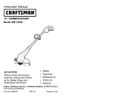
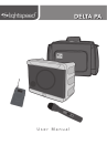
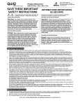
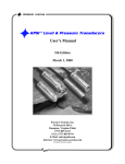
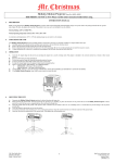
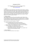
PORTABLE OUTDOOR POWERED SYSTEM POPSSUBa USER MANUAL The exclamation point within an equilateral triangle is intended to alert the user to the presence of important operation and maintenance instructions. The lightening flash with arrowhead symbol within an equilateral triangle is intended to alert the user to the presence of uninsulated “dangerous voltage” within the products enclosure that may be of sufficient magnitude to constitute a risk of electric shock to persons. NOTE: The POPS Sub uses an auto-detection circuit that senses and adjusts internal operating voltages to the AC Mains supply. The POPS Sub will operate between 104VAC and 253VAC. However, there are separate AC Mains cable assemblies for 115VAC or 230VAC operation! Although the AC Mains is automatically selected the user must insure that the proper AC Mains cable is supplied (GFCI enabled for 115VAC operation and PRCD enabled for 230VAC operation) The Portable Outdoor Powered System Sub (POPSSub) was designed by One Systems to provide additional bass and sub bass response for the POPS15 system. The POPSSub features an 18 inch (457 mm) diameter woofer that delivers extremely high acoustic output capability at very low frequencies. The POPSSub was designed for use in any direct weather outdoor application, such as sporting events, theme park events, civic celebrations and general outdoor presentations. POPSSub was designed for ALL weather applications and all components, including all electronics and transducers have been developed for use in rain, snow and other inclement weather applications. The highly portable design is also ideal for portable applications in gymnasiums, indoor and outdoor swimming pools and meeting rooms. POPSSub features large diameter pneumatic (air-filled) wheels to allow for easy transportation on soft, wet, grassy surfaces such as football fields, soccer pitches, baseball diamonds etc. Specifications Frequency Response: Coverage Pattern: 40 Hz – 80 Hz Essentially omnidirectional Input: 3-Pin XLR-type (IP 67) (Pin 2 +) Outputs: Thru (balanced) High Pass Filtered out (balanced) Power Peak - Total System: Continuous- Total System: AC Mains Power: Max Acoustic Output (Peak): Weather Performance: Supplied Accessories: 2,000 Watts 1,000 Watts 104 V AC – 253 V AC (50 Hz – 60 Hz) 128dB* IEC 529 / IP 56 AC Mains Cable (100Ft / 30.5 m) Input /Output XLR-XLR (6.6 Ft / 2 m) 1.375 inch (35 mm) manual crank-up pole Dimensions (H X W X D): 344.5 X 790 X 909.8 mm 21.44 X 31.1 X 35.82 inches Weight 40 kg (88.2 lbs) Operating Temperature 0C – 40C (32F – 104F) Available Accessories POPS 15 * NOTE: Max Acoustic Output is based on smoothed overall system response, not peak driver response. 544,5 [21,44] 790,0 [31,10] 909,8 [35,82] 790,0 [31,10] The image below shows POPS15 mounted on the POPSSub using the pole supplied with the POPSSub: Read all of the instructions included in this manual NOTE: The AC mains supply end of the POPS Sub power cable MUST be plugged into a supply source that has a GROUND FAULT CIRCUIT INTERRUPTER (GFCI). The 115 VAC version is supplied with an in-line GFCI. The 230 VAC version is supplied with a Portable Residual Current Device (PRCD). In Europe, these devices are also referred to as Residual Current Devices or Residual Current Circuit Breakers. NOTE: THE RESET ON THIS DEVICE SHOULD BE TESTED TO VERIFY PROPER OPERATION OF THE SAFETY DEVICE! The POPS Sub is supplied with an “in line” GFCI device for use in countries that use 115VAC. DO NOT bypass this device or disable. The end of the AC Mains cable that is plugged in to the AC Mains supply must be in a dry condition. The POPS Sub is supplied with an “in line” PRCD device for use in countries that use 230VAC. DO NOT bypass this device or disable. The end of the AC Mains cable that is plugged in to the AC Mains supply must be in a dry condition. NOTE: If a hard-wired GFCI or PRCD device is already located at the AC Mains source connection then the “in line” devices may be removed. THIS MUST BE DONE BY A LICSENSED ELECTRICIAN THAT IS FAMILIAR WITH ALL LOCAL AND NATIONAL ELECTRICAL CODES AND PRACTICES. DO NOT BYPASS THE GFCI OR PRCD DEVICE UNLESS YOU ARE FULLY LICSENSED AND QUALIFIED TO DO SO! Copies of this manual should be retained by both the system installer AND end user. This manual must be read and understood and ALL warnings must be followed. Follow all instructions to insure optimal product performance. Copies of this manual should be retained by both the system installer AND end user. This manual must be read and understood and ALL warnings must be followed. Follow all instructions to insure optimal product performance. POPSSub’s amplifier is a convection-cooled device and requires at least 7 inches (178 mm) of clearance behind the enclosure to allow the heat sink to adequately cool the internal electronics. SEE SECTION BELOW ON POPSSub AND HIGH TEMPERATURE AMBIENT ENVIRONMENTS AND SOLAR GAIN. DO NOT INSTALL NEAR ANY HEAT SOURCES! Use ONLY the supplied AC Mains connector. DO NOT SUBSTITUTE! Protect the AC Mains power cord from being walked on or otherwise damaged and inspect for damaged connections and damaged insulation. Use ONLY the supplied XLR/XLR cable. DO NOT SUBSTITUTE! There are NO user serviceable parts inside the enclosure. DO NOT REMOVE THE AMPLIFIER MODULE! (See Service section for details OR contact One Systems) WARRANTY ONE SYSTEMS products are warranted by ONE SYSTEMS, Inc, and ONE SYSTEMS GLOBAL Co. Ltd for a period of 5 years. (3 years for all electronic products) This warranty period begins with the date of purchase by the original end-user of the product. All products are warranted against defects in materials and workmanship. This Limited Warranty does not cover product abuse including, but not limited to, mechanical and thermal failures associated with excessive input power applied to ONE SYSTEMS loudspeaker systems. In addition, damage caused by accident, misuse or failure to observe instructions included in the following manuals: “Outdoor installation of loudspeakers” and “Rigging and Suspension of ONE SYSTEMS products” (These manuals may be found on the ONE SYSTEMS web site, www.ONESYSTEMS.com) is not covered. Other acts which are not the fault of ONE SYSTEMS are not covered. Defects or damages resulting from service, testing, product modification or alteration by someone other than ONE SYSTEMS or its authorized agents or service centers are not covered. ONE SYSTEMS is not responsible for misrepresentations by the seller or other parties. All products covered by this limited warranty must be shipped to an authorized service center (see details below) prepaid. ONE SYSTEMS will pay all material and labor costs associated with repair or replacement of covered products. ONE SYSTEMS will pay all return costs associated with products covered under the terms of this limited warranty. Limitation of Implied Warranties ANY IMPLIED WARRANTIES, INCLUDING WITHOUT LIMITATION THE IMPLIED WARRANTIES OF MERCHANTABILITY AND FITNESS FOR A PARTICULAR PURPOSE, SHALL BE LIMITED TO THE DURATION OF THIS LIMITED WARRANTY, OTHERWISE THE REPAIR, REPLACEMENT, OR REFUND AS PROVIDED UNDER THEIS EXPRESS LIMITED WARRANTY IS THE EXCLUSIVE REMEDY OF THE END USER (CONSUMER), AND IS PROVIDED IN LIEU OF ALL OTHER WARRANTIES, EXPRESS OF IMPLIED. IN NO EVENT SHALL ONE SYSTEMS , OR ANY OF ITS OPERATING DIVISIONS, BE LIABLE, WHETHER IN CONTRACT OR TORT (INCLUDING NEGLIGENCE) FOR DAMAGES IN EXCESS OF THE PURCHASE PRICE OF THE PRODUCT, ACCESSORY OR SOFTWARE, OR FOR ANY INDIRECT, INCIDENTAL, SPECIAL OR CONSEQUENTIAL DAMANGES OF ANY KIND, OR LOSS OF REVENUE OR PROFITS, LOSS OF BUSINESS, LOSS OF INFORMATION OR DATA, SOFTWASRE OR APPLICATIONS OR OTHER FINANCIAL LOSS ARISING OUT OF OR IN CONNECTION WITH THE ABILITY OR INABILITY TO USE THE PRODUCTS, ACCESSORIES OR SOFTWARE TO THE FULL EXTENT THESE DAMAGES MAY BE DISCLAIMED BY LAW. Some states and jurisdictions do not allow the limitation or exclusion of incidental or consequential damages, or limitation on the length of an implied warranty, so the above limitations or exclusions my not apply. This warranty provides specific legal rights, and other rights may exist from state to state or from one jurisdiction to another. REGULATORY AND SAFETY DATA This product was tested to International Standards for safe operation. The POPSSub is compliant with EN60065. Test certification may be obtained from One Systems. CONTENTS The POPSSub system is shipped in three cartons. The contents of the cartons are as follows: POPSSub ENCLOSURE One Portable Outdoor Powered Systems Sub (POPSSub) that includes a classD digital power amplifier. The complete POPSSub is rated to IEC 529 / IP 56. Also included in this carton is a 1.375 inch (35 mm) standard diameter mounting pole for use with POPS15. NOTE: The POPS Sub MUST be located on level ground when the POPS 15 is mounted on top of the supplied pole. DO NOT USE OTHER SYSTEMS THAN THE POPS15 WHEN MOUNTING ON THE POLE. DO NOT SUBSTITUTE OTHER MOUNTING POLES ON POPS Sub’s ENCLOSURE! AC MAINS CABLE 100ft (30.5 m) of SJOW-rated AC mains cable with an IP 68-rated cable end connector designed to mate to the input panel of the POPSSub enclosure. INPUT/OUTPUT CABLE 6.6 FT. (2 M) of SJOW-rated two-conductor shielded input/output cable with an IP 67 rating. FEATURES AND APPLICATIONS POPSSub is a very unique product and may be used in “wet” outdoor environments. Its AC Mains and input/output connectors are designed to provide a high degree of ingress protection. All mechanical connections are rated IP 67 or higher. POPSSub may be safely installed in outdoor environments as long as ONLY the supplied cables are utilized. DO NOT SUBSTITUTE CABLES. POPSSub is a professional product and is designed to be used with a highquality mixing console. The POPSSub does not provide any additional, userselectable equalization. Equalization functions should be provided by the mixing console or other outboard devices. One Systems does not feel that adding additional EQ functions are appropriate for truly professional products. The addition of redundant functions such as EQ can cause of clipping and distortion. The system’s dynamics processing consists of a compressor/limiter function designed to provide both ultra fast threshold system protection and maximized system dynamics. POPS AND HIGH AMBIENT TEMPERATURES POPSSub has been designed to work in a wide range of ambient temperatures. When using the POPSSub however, consideration must be given to the ambient temperature as well as the heat produced by exposure to direct sunlight. In a “shaded” environment, the POPSSub is rated for normal operation up to 40o C (104o F). In environments where POPSSub is subjected to direct sunlight, a portion of that direct solar energy is absorbed by the enclosure and the external heat sink. POPSSub’s color and resin formulations have been specifically designed to minimize the thermal/solar gain of the enclosure and the heat sink has been clear-anodized to minimize its solar gain as well. It is recommended that whenever possible, POPSSub should be used in either a shaded area, or in shade provided via an external “umbrella” type of sun shade. Solar gain precautions should be taken any time the ambient (air) temperature is 90o F (32o C) or higher and if POPSSub is intended to be used in direct sunlight. SETUP AND USE OF POPSSub AC MAINS CONNECTION The AC mains are connected to the POPS Sub using the supplied cable ONLY. DO NOT SUBSTITUTE! NOTE: If the POPS Sub is being used with the POPS 15 the best practice is to turn on the POPS 15 PRIOR to turning on the POPS Sub. During the turn off sequence, either the POPS 15 or the POPS Sub may be turned off first! Prior to connecting the AC mains cable, insure that the AC mains switch on the POPSSub is in the OFF position. On/Off Switch NOTE: DO NOT CONNECT THE AC MAINS CABLE TO THE POPSSub IF WATER OR MOISTURE IS PRESENT IN THE CONNECTOR! POPSSub will operate on any AC mains voltage between 104 volts and 253 volts. The required AC mains frequency is between 50 Hz and 60 Hz. POPSSub uses a waterproof AC mains connector system. To mate the AC mains cable with the AC mains connector on the input plate, align the cable end with the amplifier’s panel connector and push with sufficient force until you hear a “click” sound that indicates the cable end and chassis end are properly mated. Support the POPSSub’s enclosure with one hand while performing this operation. The AC mains connector is shown below. It is located on the lower portion of POPSSub’s input panel. AC Mains panel connector INSURE THAT THE AC MAINS CABLE IS SECURLY CONNECTED AND IS “LOCKED” INTO POSTION. DO NOT USE THE POPSSub IF THE AC MAINS CONNECTOR IS NOT SECURLY-MATED TO THE AMPLIFIER MODULE! DO NOT CONNECT THE AC MAINS END OF THE AC MAINS CABLE IN AN AREA THAT IS WET OR SUBJECT TO CONDENSATION OR DAMP CONDITIONS! The AC Mains end of the cable assembly uses an “in-line” GFCI device (115 V AC) or a PRCD device (230 V AC). DO NOT disconnect this device! To disconnect the cable end of the AC mains connector, pull back on the collar of the cable’s end connector in the direction shown on the connector. While pulling back on the collar, pull the cable end connector away from the chassis connector. NOTE: ALWAYS turn off the AC mains power BEFORE attempting to disconnect the AC mains cable from POPSSub’s amplifier module! The AC mains supply end of the cable is shown in the image below. Cable end (connected to POPS Sub) AC Mains end Once the AC mains cable is connected to POPSSub’s electronics, the other end of the AC mains cable may be connected to the AC mains supply. This end of the AC mains cable is a standard connector and MUST be connected in an area that is DRY. The figure above represents both ends of the AC mains cable. The connector on the left side of this figure is the IP 68-rated cable end that should be connected to the AC mains input on POPSSub’s amplifier module. The connector on the right side of this image is connected to the AC mains supply located in a dry area. (The connector shown on the right side will vary depending on local AC Mains connection requirements!) NOTE: The AC Mains cable is an extension cable. It is a high-quality cable with low line loss. Connecting the AC Mains cable to another extension cable will produce additional line loss and can result in low ac mains voltage at the POPS amplifier module. It is not recommended that additional extension cables be used with this AC Mains connector. Once the AC mains cable is securely connected to both the amplifier and AC mains supply end, POPSSub may be powered up. A good practice is to make sure the audio levels on the mixer’s output (or other source output) are reduced or muted prior to applying power to POPSSub. NOTE: When power is applied to the POPSSub and the unit is turned on, there is a short delay before the pilot light illuminates. Pilot Light NOTE: If the pilot light does not illuminate within 30 seconds the unit may be in a FAULT CONDITION. The unit should be returned to One Systems for evaluation. THERE ARE NO USER-SERVICABLE PARTS INSIDE. DO NOT REMOVE THE AMPLIFIER MODULE! AUDIO CONNECTIONS POPSSub includes two male XLR connectors. This configuration differs from the standard male input and female out/thru due the to water and moisture requirements of this product. Both the input and output/thru XLR connectors on the POPS Sub are male Neutrik plugs and require Neutrik cable end connectors NC3FXX-HD-D. The supplied XLR to XLR audio cable has two of the NC3FXXHD-D connectors. The POPS Sub also features a High Pass Filters output. This output is a 4th order (24dB/Octave) high pass output designed to provide a drive signal to the POPS 15 enclosure. This is a balanced output with pin 2 positive. The image below illustrates the top portion of POPSSub’s input plate. Both the audio input and audio thru connectors as well as the HP filtered output are shown. In this image all connectors are shown with their water covers in place. NOTE: POPSSub also features an audio “signal present” indicator LED that is next to the Pilot Light. This indicator will illuminate when there is an audio signal present at the XLR input. The threshold for this indicator is approximately -25dBV. When the audio connectors are not in use, the water covers should be inserted in the XLR connector. (Example: If the audio input is being used but the audio thru connector is not being used, the water cover should be inserted in the audio thru XLR to prevent moisture intrusion). Audio Input, Thru and HP Filtered Weather Covers The image above shows both the input and thru connectors with water covers in place. NOTE: Care must be exercised to insure that each end of the XLR connector is securely seated in the mating panel connector and locked into place. Insert the connector into the panel connector until a soft “click” is heard. This indicates the cable end is properly mated to the panel connector. To remove the XLR connector simply squeeze the rubber “boot” of the connector on the top and bottom as near to the panel end of the boot as possible. Failure to properly seat and secure the connector will reduce the water protection features designed into the connector assembly. Audio Input The POPS Sub also features an audio “thru” output. This connection MUST also use a Neutrik NC3FXX-HD-D cable end connector. Audio Input Audio “Thru” Output Connect the audio output from the console/mixer using the supplied XLR to XLR cable using the Audio Input XLR as shown below. The wiring is also shown below for the POPSSub and POPS15. POPS 15 Input From Mixer Console Output to POPS Sub Input POPS Sub High Pass Output to POPS 15 Input As noted above, the mixing console’s output is wired to the POPS Sub’s input. The POPS Sub’s High-Pass Output is wired to the input of the POPS 15. The XLR connectors supplied with POPS15 and POPSSub must be used for these connections. DO NOT SUBSTITUTE! DO NOT USE THE CONNECTOR IF MOISTURE IS PRESENT IN THE PANEL PORTION OF THE XLR CONNECTOR. THE PANEL’S CONNECTOR MUST BE DRIED PRIOR TO CONNECTION! WARNING: DO NOT SUBSTITUTE XLR CABLE END CONNECTORS. FAILURE TO USE NEUTRIK NC3FXX-HD-D CABLE END CONNECTORS WILL COMPROMISE THE WATER / MOISTURE RATING OF THE POPSSUB AND MAY RESULT IN UNSAFE CONDITIONS. NEUTRIK NC3FXX-HD-D CONNECTORS MUST BE USED FOR ALL CONNECTIONS ON THE POPSSUB. USING THE POPSSub (Application and Trouble-Shooting Tips) POPSSub is a high-quality professional sound reinforcement system designed for use in both direct weather outdoor applications as well as high ambient noise indoor applications. The POPSSub is designed to be used with the POPS15. Some basic precautions will insure long-term reliability. INSURE THAT THE POPSSub IS PLACED ON LEVEL GROUND THAT IS CAPABLE OF SUPPORTING THE WEIGHT OF BOTH THE POPSSub AND THE TOP POLE-MOUNTED ENCLOSURE . FAILURE TO INSURE A FLAT SURFACE THAT IS CAPABLE OF SUPPORTING THE ENTIRE WEIGHT OF THE POPSSub AND POPS15 MAY RESULT IN INJURY AND PROPERTY DAMAGE! GAIN POPSSub has an external gain control designed to match the subwoofer’s acoustic output with the POPS15. Care should be exercised when setting this gain level to insure that the overall system gain structure is below the system’s electronic overload (below clipping levels). The optimal “starting” point of the POPSSub’s gain function is at the 50% rotation position. (half-way between the rotation extremes of the gain function control) In this position, adding the POPSSub’s output to the output of the POPS15 will increase the low-frequency output at 50 Hz by 6 dB and over 8 dB at 40 Hz. Increasing the gain control to max will produce approximately another 4 dB of output from the 50% position. Rotating the gain in the counter clockwise direction from the 50% position will rapidly reduce the gain of the POPSSub. The output gain of the mixing console should be set at a low level and then the gain of the POPSSub should be set to the desired level to achieve the required overall system acoustic response. Then the gain of the mixing console should be increased to achieve the desired output levels. If any distortion or clipping is detected, the gain of either the mixing console output or the gain of the POPS Sub should be reduced. The POPSSub’s gain control location is shown in the picture below: POPS Sub Gain EQUALIZATION The POPSSub has all the required equalization functions included in its amplifier’s circuity. The equalization functions have been optimized for flat frequency response and maximized system dynamics. POPSSub does not have user-adjustable external EQ. The mixing console should be capable of providing sufficient output signal levels to supply the necessary voltage levels to drive the POPS15 and POPSSub to full power and still insure adequate headroom. The mixing console should be capable of driving 100 feet (30.5 m) of balanced cable as well as the POPS15. If additional equalization is required, care should be taken to avoid excessive EQ in any band, but particularly at low frequencies. Excessive equalization can produce “band selective” clipping and distortion. All EQ boost levels should be monitored if system distortion is present. DISTORTED SOUND When input levels to the POPSSub exceed the amplifier’s gain capability, internal dynamics processing functions will engage and provide system protection. However, it is still possible to “overdrive” the input section of the enclosure. If distorted sound is present the following steps should be taken: 1. Verify that the mixer’s output is not clipping or overloaded. If the output metering section of the mixing console is continuously in the “red” then the output level should be reduced. (occasional “red” indications are usually fine and are dependent on the mixing console output capability). 2. Verify that excessive equalization is not present anywhere in the signal chain. 3. Verify that AC mains levels are within the required range. Voltage measurements on the AC Mains should be performed by a licensed electrician or individual trained in making high voltage measurements. NO SOUND 1. Verify that signal is present on the input of POPSSub. 2. Verify that there is AC Mains voltage on the AC Mains input to the POPSSub 3. If AC Mains voltage is present, verify that POPSSub’s fuse is not blown. NOTE: IF THE FUSE IS BLOWN, REPLACE ONLY WITH THE SAME TYPE OF FUSE. THIS FUSE TYPE IS NOTED ON THE INPUT PANEL NEAR THE FUSE HOLDER. THE LOCATION OF THE FUSE HOLDER IS SHOWN BELOW. FUSE HOLDER The fuse holder is a waterproof design. Insure that the gasket is properly seated when replacing the fuse. Insure that the fuse holder cover is securely tightened. DO NOT OVER-TIGHTEN THE FUSE HOLDER’S COVER. PRODUCT SERVICE There are NO user-serviceable parts inside the POPSSub. NOTE: See section below titled “Replacement of Components” for woofer servicing. The POPSSub’s amplifier module MUST be serviced by an individual authorized by One Systems. POPSSub’s amplifier is attached to POPSSub’s enclosure using 12 x M4 stainless steel machine screws with self-sealing washers. The unique selfsealing feature of these washers forms a waterproof seal between the amplifier module and the enclosure. The washers are supplied by Gaynor Industries and are Gaynor Industries part number LTN37164 DO NOT SUBSTITUTE WASHER TYPES. Replacement of Components REPLACEMENT OF COMPONENTS MUST BE PERFORMED BY A QUALIFIED TECHNICIAN OR ONE KNOWLEDGABLE IN THE REPLACEMENT OF TRANSDUCER COMPONENTS! DO NOT ATTEMPT ANY REPAIRS UNLESS POPSSUB’S AMPLIFIER HAS BEEN DISCONNECTED FROM THE AC MAINS SOURCE! In the event of woofer failure, the woofer may be accessed by removing the front grill and then removing the woofer. This should be done by a qualified technician or contractor. There is no need to remove the amplifier panel in the event of a woofer failure. USE EXTREME CARE WHEN HANDLING POPSSUB’S AMPLIFIER MODULE. THE COMPONENTS ON IT ARE FRAGILE. THE MODULE MUST NOT BE SET ON ITS COMPONENT SIDE OR DAMAGE WILL OCCUR! © One Systems, Inc. 2012 www.onesystems.com