1
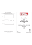
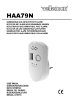
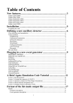
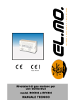
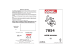
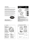
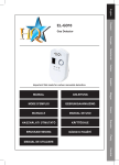
INSTALLATION CERTIFICATE
The undersigned qualified installer attests to have personally fitted the here described detector on the
following vehicle, according to the manufacturer’s instructions.
By:
Sold on :
Type of device :
911
................................................
Narcotic Gas
and
Explosive Gas
Wireless Detector
911
Vehicle :
..........................................................................................................................
INSTALLATION AND USE
MANUAL
UK
GEMINI Technologies S.p.A.
Via Luigi Galvani 12 - 21020 Bodio Lomnago (VA) - Italia
Tel. +39 0332 943211 - Fax +39 0332 948080
www.gemini-alarm.com
Reg. n.532-A
For all EU Countries
AC 2782UK Rev. 00 - 12/09
UK
1.0 - INTRODUCTORY NOTE
CONTENTS
1.0 - INTRODUCTORY NOTE........................................................ PAGE 03
USER MANUAL
2.0 - OPERATION DESCRIPTION................................................. PAGE 03
2.1 - STARTING AND WARMING UP............................................ PAGE 03
3.0 - ALARM SIGNALS.................................................................... PAGE 03
3.1 - NARCOTIC GAS ..................................................................PAGE 04
3.2 - LPG EXPLOSIVE GAS ........................................................ PAGE 04
4.0 - POWER SUPPLY.....................................................................PAGE 04
4.1 - RELAY OUTPUT................................................................... PAGE 04
5.0 - SELF-DIAGNOSIS...................................................................PAGE 05
6.0 - SENSITIVITY LEVEL SELECTION......................................... PAGE 05
7.0 - IMPORTANT CAUTIONS........................................................ PAGE 05
8.0 - SYMBOL INDICATIONS..........................................................PAGE 06
8.1 - YELLOW LED SIGNAL INDICATIONS................................. PAGE 06
9.0 - WARRANTY CONDITIONS.................................................... PAGE 06
INSTALLER MANUAL
10.0 - INSTALLATION......................................................................PAGE 07
10.1 - FITTING OF DETECTOR................................................... PAGE 07
10.2 - ELECTRICAL CONNECTIONS.......................................... PAGE 07
10.3 - MOUNTING DIAGRAM...................................................... PAGE 07
11.0 - RELAY OUTPUT CONNECTIONS........................................ PAGE 08
12.0 - CIRCUIT DIAGRAM.............................................................. PAGE 08
13.0 - CORRECT POSITION FOR LPG DETECTION.................... PAGE 09
14.0 - TECHNICAL SPECIFICATIONS............................................PAGE 10
15.0 - WASTE ELECTRICAL AND ELECTRONIC EQUIPMENT
DIRECTIVE (WEEE)............................................................. PAGE 10
Dear Customer,
Thank you for purchasing a Gemini product.
The present manual has been written to help you understand and use the
narcotic and LPG detector 911, specifically designed for recreational vehicles.
Read the supplied instructions thoroughly and keep them handy.
USER MANUAL
Should gas be sprayed into your vehicle, the 911 sensor is able to detect it and
set off an alarm in a few seconds, long before the gas can have any effect on
the occupants.
The 911 detector also activates the output relay which actuates other devices
(ex. cabin lights, vehicle horn, etc.) to discourage anyone trying to break in
your motorhome.
N.B. In compliance with European standard En50194, the detector can
signal the presence of explosive gas (LP), when its concentration is
higher than 10% of the LEL (Lower Explosive Limit, the minimum
concentration which can cause an explosion).
2.0 - OPERATION DESCRIPTION
We recommend operating the detector only when the vehicle is parked at
bedtime.
If the detector is switched on uselessly (ex. While driving, when the vehicle is
stowed away, etc.), the detecting probe may exhaust.
2.1 - STARTING AND WARMING UP
When power is applied to the detector, it will go through a warm-up period and
will be inhibited for at least 3 minutes; during this so-called “warm-up” phase,
the yellow LED will blink.
This phase is necessary to allow the sensible element to warm-up and stabilize
itself in order to ensure proper operation conditions.
After this time delay, the yellow LED turns off and the detector is ready to work.
!
PAGE 02
The 911 detector does not detect Carbon Monoxide (CO).
USER MANUAL - PAGE 03
3.0 - ALARM SIGNALS
5.0 - SELF-DIAGNOSIS
3.1 - NARCOTIC GAS
Thedetector continuously monitors the narcotic gas concentration level in the
cabin by carrying out calculations to self-adapt to the different air quality
conditions (use in urban areas is different from use in country places).
If a sudden increase in the concentration level is detected due to narcotic
gases being sprayed in the vehicle, the detector immediately activates the
siren and the output relay.
The alarm state remains ON until the conditions which have triggered it are
present.
To deactivate the alarm, simply disconnect it.
The detector is provided with an acurate and reliable self-diagnosis system
which continuously checks its performance and efficiency; any failure or the
exhaustion of the probe, after a life cycle of more than 11,000hrs, is signaled by
the yellow LED turning ON and by a warning alert signal.
3.2 - EXPLOSIVE GAS LPG
The detector continously monitors the LPG concentration level in the cabin; if
its concentration exceeds 10% of the LEL (Lower Explosive Limit), the detector
immediately activates the siren and the output relay.
The alarm state stays on until the conditions which have generated it are
present.
Important Note: for LPG detection, the sensor must be installed according to
the installation instructions (see chap. 13.0).
!
When the probe is exhausted, contact an authorized dealer for
replacement or reconditionning of the detector.
6.0 - SENSITIVITY LEVEL SELECTION
By default, the detector is set to “normal” sensitivity; in case of particular
environmental conditions, the sensitivity can be set to “low” by opening or
interrupting jumper P1.
Jumper P1: closed = normal sensitivity
Jumper P1: opened = low sensitivity
!
Changing the sensitivity setting will not modify the alarm threshold
level for explosive gas LPG, 10% of the LEL.
7.0 - IMPORTANT CAUTIONS
4.0 - POWER SUPPLY
The detector can operate both at 12V or 24V, by setting the voltage switch Sl1.
!
By default, the detector is set at 12Volt.
The 911 is equipped with a relay that actuates other devices (ex. cabin
lights or vehicle horn or any other alarm device).
The relay supplies the contacts NC - C - NO on the terminal block M1 (see
connection example in par. 11).
PAGE 04 - USER MANUAL
! Use only a damp cloth to clean the detector; do not use thinners (alcohol,
detergents, etc.) which could irreparably damage the detector.
! Alcohol based cleaning agents, perfumes, deodorants, varnish thinner
fumes, insecticides and other sprays can interfere with the correct
operation of the sensor and create improper alarms and/or alter the device
sensitivity.
! Silicone vapors in the cabin can deteriorate the detector sensing element.
USER MANUAL - PAGE 05
INSTALLER MANUAL
8.0 - SIGNAL SYMBOLS
SYMBOL
!
COLOR
DESCRIPTION
Green
Supply voltage present
Ye l l o w
Signaling of specific functional conditions
(see table 8.1)
Red
Power ON - alarm ON
8.1 - YELLOW LED SIGNAL INDICATIONS
YELLOW
LED
ACOUSTIC
ALERT
D E T E C TO R
CONDITION
Consecutive
flashings
None
Starting and warming up
On steady
Short beep
every 5 minutes
Out of order due to exhaustion of
probe (after 11,000 working hrs)
On steady
None
Faulty
9.0 - WARRANTY CONDITIONS
This product is guaranteed to be free from defects in workmanship for a period
of 24 months from the date of installation reported on the present warranty, in
compliance with the1999/44/CE Warranty Directive (L.D. N° 24 02/02/2002).
Please fill-in entirely the guarantee certificate included in this manual and DO
NOT REMOVE the guarantee label affixed to the device.
The warranty will become void if labels are missing or torn, if the installation
certificate is not fully compiled or if the enclosed sale document is missing.
The warranty is valid exclusively at authorized Gemini Technologies centers.
The manufacturer declines any responsability for eventual malfunctions of the
detector or any damage to the vehicle electrical system due to improper
installation, use or tampering.
10.0 - INSTALLATION
The 911 detector is intended for a permanent installation.
The device must be positioned at about 20-40 cm from the vehicle cabin floor
to be protected.
The detector must be installed at least 1-1,5m away from any air supply
register; if there is an air intake vent, install the detector near it.
10.1 -FITTING OF DETECTOR
! Remove the detector cover by prying lightly with a screwdriver inserted in
the release slot on the right side of the casing.
! The two screw holes (FF) can be used to mount the detector to a wall or
onto a base (fig.1); the electronic card must first be removed by unscrewing
the screw on the bottom right corner. (see par.13).
10.2 - ELECTRICAL CONNECTIONS
! The pre-drilled holes (FC) are used to run the power wiring (see par.12.0).
! Connect the wires that supply 12 or 24V to the terminal block M2 (see par.
12); depress the supply terminal block to introduce the cables which must
have a section comprised between 0,5 and 1,5 mm².
! Remove 9mm of sleeve from the cable before inserting it in the terminal
block; release the push-button and pull on the cable to make sure it is well
secured.
! The auxiliary devices conductors intended to manage the alarm must be
connected to terminal block M1; the maximum rating of the relay contacts is
2A at 28Vdc (refer to par. 13). To actuate devices having a higher
absorption rate, an auxiliary relay must be provided.
10.3 - MOUNTING DIAGRAM
FC
FC
FR
FF - Pre-drilled mounting holes, use the
ones to the far ends.
FC - Pre-drilled holes to run the cables,
use the ones on the left for the power
cable.
FR - Power supply cable holder.
FF
Figure 1
PAGE 06 - USER MANUAL
FC
INSTALLER MANUAL - PAGE 07
13.0 - CORRECT POSITION FOR LPG DETECTION
11.0 - RELAY OUTPUT CONNECTIONS
The maximum relay contact capacity is 2A at 28Vdc; to actuate devices having
a higher absorption rate, an auxiliary relay must be provided.
!
The detector must be installed at about 20-40cm from the floor as illustrated
here below.
For safety reasons, always insert a protection fuse (3-4A max.)
between the device to be managed and the detector contacts.
Min 1 meter
Max 5 meter
Model 911
20/40 cm
12.0 - CIRCUIT DIAGRAM
Alarm
output
Card fixing
screw
M1 - Screw-type terminal block to connect alarm output contact.
M2 - Push-button type terminal block for 12V or 24V.
SL1- Voltage switch 12 or 24V.
P1 - Sensitivity level selector.
PAGE 08 - INSTALLER MANUAL
INSTALLER MANUAL - PAGE 09
14.0 - TECHNICAL SPECIFICATIONS
Power supply selectable via the
SL1 switch
12Vcc (10 to 14Vcc)
24Vcc (20 to 28Vcc)
Maximum absorption
100mA
Alarm sound pressure level
90dB at 30 cm
Working temperature
Da +5°C a +45°C
Dimensions
117 x 68 x 35 mm
Protection level
Ip40
Plastic casing
and inflammability class
PC - Polycarbonate
V2 - GW 750
Approximate weight
200gr
Relay contact rating
2A max. at 28Vdc
15.0 - WASTE ELECTRICAL AND ELECTRONIC EQUIPMENT
DIRECTIVE (WEEE)
In the European Union, this label indicates that, this product, must not be
disposed of with household waste. It should be deposited at an appropriate
facility to enable recovery and recycling (Directives 2002/95/CE, 2002/96/CE
and 2003/108/CE).
For information on how to recycle this product in your country visit: www.eurlex.europa.eu.
!
APPROPRIATE
CONTAINERS
ONLY
PAGE 10 - INSTALLER MANUAL