1
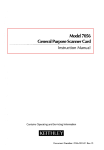
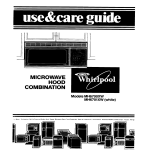
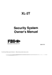
.. .
N7658V1 Rev, B 11/95
QUEST 2000
(ADEMC~J
Adlvanced Image Processing
Motion Detector
INSTALLATION INSTF?UCTIONS
GENERAL INFORMATION
Ademco has taken the next step on motion detector
technology with the QUEST 2000, Ademco’s Image
Processing detector.
The QUEST 2000 is a “thinking” detector which uses a
combination of two diverse methods of detection to
improve false alarm immunity. The passive infrared
detector provides 22 zones of wide angle coverage with a
range of 40 feet (12.2 m). In addition, there is a “lookdown” zone that provides protection in the area close to
the mounting wall. A microwave detector provides alarm
verification.
,-
The PI R optical system divides the area into a seties of
protected zones. A dual element PIR sensor measures the
level of infrared energy in each zone. The microwave
system provides a volumetric coverage pattern. When an
intruder enters the combined PIRlmicrowave protective
pattern, PIR and microwave signals will be generated at
the same time and the detector’s relay will repofi an alarm.
The QUEST 2000 includes a microprocessor with analogto-digital conversion which provides:
. Dual technology signal processing for immunity to
environmental disturbances and reduced false alarms.
● Ademco
image processing of 256 different environmental contrition levels.
. Adaptive microwave signal processing for false alarm
immunity.
Tha microwava detection pattern shown in Diagram 1
repreaenta coverage in open space. In practical applicafiona, when the detector ia bounded by ceiling, floor, and
walla, reflections occur and the device provides volumetdc
coveraga.
Selecting a Mounting Location
The detector responds to changes in energy which occur
when an irbtrudarmoves into the combined protection pattern. Best t:ovarage will ba obtainad if tha mounting site is
selected so that the likely direction of intruder motion is
genarally ;tcross the pattern and angles slightly toward the
detector (see Magram 1),
TOPVlw
20’
1
.........
MICROW~V:,,...’”’””
A
........
.....
~~~~~
. 40 ft (12m) x 50 ft (15m) range with “look-down” zone.
Adjustable microwave range with potentiometer.
. Rejection (with digital notch filter) of fluorescent light
disturbances.
. Trouble output. Unit pedorms self-test and repotis a
failure. Unit continues to operate as PIR only.
●
. Alarm LED local and remote disable.
. Dgital pulse count and pulse recognition provides false
alarm immunity in harsh environments.
● True digital temperature comp6nsafion.
. DIP switch selectable functions: walk test, Pulse Count
3 (PIR), Alarm LED disable.
. Ademco ACCU-TRAK
walk test faature for faster
installation.
These additional conventional features are included:
. Dust etement pyroatactric PIR sensor and Fresnel
ODfiCS.
. Superior lens design. Does not require any optics
adjustment.
* Low current drain, which allows for extended
sourca standby batte~ life.
●
12VDC operation.
. Wall and cornar mounting brackat providad.
-
●
power
Optional swival bracket is availabla.
COVERAGE AND LOCATION CONSIDERATIONS
Combined protective pattarns are shown in Diagram 1, for
a nominal mounting height of 7.5ft (2.3m).
❑iagram
1: PROTECTION
PA~ERN
lnstallatio,n Hints
The detector is remarkably resistant to false alarm
hazards, but the following racommendafions should be
obaewed:
. Select ?I mounting haight approximately
7.5ft (2.3m)
above the floor.
. Do not nlount on an unstable sutiace. Locate the unit on
a sturdy inside wall whenever possible. Avoid sources of
vibmtion such as loose fitting doors and walls that shaka
whan heaq traffic exists.
. Do not install on or close to metal structures such as
metal door framas, shelves, ate.
. Do not include space haatars in the protective pattern
whenavt?r possibla, to avoid rapid temperature changes
and vib~sfion from fans.
●
Avoid aiming directly at a fluorescent light. Keep at Ieaat
20ft (6.1 m) away from them if possible. They present
variable reflections to the microwave aeneor.
* Microwave transmission penetrate
most building
material (except metal, which reflacts transmission).
Moving objects outside of the protected area may,
therefore, be detected unless the microwave sensitivity
control is kept at as low a sening as possible, to minimize penetration,
● Make
sure the detection
area does not have
obstructions (cutiains, screens, large pieces of furniture,
plants, etc.) which may block the PIR portion of the
coverage pattern.
Impotiant Avoid running alarm wiring close to heavy duty
electrical power cables,
u
D~ECTOR
LOCKING
TAa
no
<y
~
@
[~
MOUNTING HOLES
WALL (3)
INSTALLATION
Mounting
1. Remove front cover by twisting a screwdriver blade in
the groove between cover and base at the location
shown in Diagram 2 and then bffing the cover off,
Diagram 3
Wiring Ccmnactions
CORNER (4)
WALL PLATE
(see Diagram
4)
Bring all wires through the unifs wiring ent~ near the
terminal block and make connections as indicated in
Diagram 4 and in the table below.
2. Mount wall plata to a firm vertical surface (flat on wall
or in corner). Position the plate ao that field wiring is
centered in the hole at the top of the plate [wall wiring
hole no larger than 5/16
(8mm) diameter]. See
Diagram 3,
TERM
3. Feed wiring through the wiring hole in the bracket, and
via the wiring trough at the rear of the base through the
wiring hole in the base. Do not connect to terminal
block yet.
4. Attach unit to wall plata by engaging all four hooks on
the plate into slots on the rear of the base and by
sliding the unit downward, See Diagram 3.
Note: The unit is locked to the wall plate by a plastic
spting tab in the plate that engages an opening in
the housing base (sea Diagram 3). The unit can
only be removed from the plata by removing the
cover, depressing the tab (via a hole in the base)
with a small blade screwdriver, and then stiding the
unit upward (see Diagram 4),
FUNCTION
1
+12 Vlnput Supply. Powar muat be provided
from a 12VDC filtered source with 25mA
capability and at least 4 hours of standby
batfe w caoacitv.
2
(-) Input Supply (ground).
3&4
Use of the wall plate provided is recommended. If you
choose nOt to use the wall plate, knockout holes for direct
wall or corner mounting are provided in the unit’s base (to
gain access to them, the circuit board must be carefully
removed from the base by bending back the circuit board
holding tab at the Iowar edge of the board). Do not use the
unit$ “wall plate keyholes” for direct mounting; use the
mounting holes above the ,Ckeyholes”(or to the left and
right of the ‘keyholes” for corner mount).
Relay Contacts. N.C.(open on alarm),
Connect to closed protective circuit,
5
Alarm LED Remote Disable.
Apply+12Vto.
disable-alarm indication (Same assening DIP
switch #3 UP).
6
Trouble Output. Upon aupewision failure, this
open collector output will go low (requires
1000-ohm pull-up resistor). Useahielded wire
for UL installations.
_
Locally, both LEDs will flash to annunciate
trouble. The detector continues to operate as
PIR only.
Adjustments
and Selections
MICROWAVE SENSITIVIW CONTROL:
Turn the Potentiometer clockwise to increase sensitivity.
DIP SWITCH S~lNGS:
#1: UP for Walk Teat selection (relay will remain open
while Test is eelected),
I
#2: UP for setting Pulse Count to 3.
#3 UR foralarm LED daable (disables
1
alarm
indication
only).
#4
UNUSED
TESTING
Irrrpomant Wait at Iaast two minutes after applying power
before attempting to walk-test unit.
Conduct the walk testing of the detector with the protected
area
cleared
of all people,
[n come
business
establishments, it may be more convenient to do ttis afler
the business ia closed, The protective system’s control
should be disarmed during the procedure to prevant
repoting unwanted alarms.
1I mIST scRNDRY=R BMDEINGROOvE.
21Ll~ COVEROFF,
Diagram 2
COVER REMOVAL
2
-
R
.-.
12~ lNP~
AmRMREmVCONTACT
[N.c.OPENONAURM,
ED REMOEDISABLE
WEN 7WC APPLIEW
SPECIFICATIONS
Oe&ction Mathod Dual Technology
Mcrowave/PiR.
~OUBLE
COvaraga
OUP~
FOR SUPERWSlON.
.USE SHIELDED WIRE FOR UL lNSTALMn~S
r
WWR
AND CIRCU~
4111
(+)(-)A
ttI-L
BOARD—
HOWINGPOSTS[21
WOOKCOVER
ONTH=E
HEN REPUCINGm
123458~!
:
. ..... ...
40ft(12m)x50ft(15m),
Oetection Pattern:
~
22 ZOnes (7 Main, 6 Mdrange,
5 Intermediate, 4 Close) plus one
.Look-down. zone.
b
WIRING ENmY HOE
AND WIRING CWNEL
IN BEE
Mcrowave:
VOlumetfic covemge.
Mounting Helghk 7.5ft nominal (2.3m),
walllcomer mounting.
Indicators Red and Green LEUS(see
LED INDICATIONS in
MICROWAE
DHEmOR
(DRO)
Diagram 4).
Alarm Relay SPST (Fore A) reed with
15-ohm protective resistor,
COnmo*.
50 mA max at 24VDC
(non-ind.ctiva).
,
LOCKINO
RELmEACCE=
W REL=SE
UN!T\
FROM
WAWPWTE,
INSEmSRWDBIVER
BUDE,
P~SSS
kUINSTLOCKING
TAB,
ANDSLIDE
UNIT
Up.
MICROWAE
SENSlnMW
CON~OL.
NRN CLOCWISE M
INCRUSE ENS~lVIN
Input VohagS 12VDC nominal.
(&J::$::::~etector
inoperative.)
Current
CIRCUIT 00ARO HOLDING TAB—
(BEND WCK IF NECEWRY
TO REMOE BOARD)
.
PIR D~CTOR
y
“LOOK-NW”
Standby
CapabiliW
LENS
25mA (40mA during
power UP).
Powersourceshouldbe
capable of at least 4 hour!
of batte~ stindby.
Operating
Temperature +14°F to +122-F
(-lo~c
to +50”C)
RED LED
(SEE BELOW
GREEN LED
(SEE BELOW
Operating
HumidiW
Up to 95Y. RH (mW.) noncondensing.
Dimensions ~-~~~~e:W
.
LED INDICATIONS:
POWER UP Red and Green LEDs on for approx.90 sem.
SUPERVISION FAILURE: Red and Green LEDs flasfdng.
ALARM: Red LED on.
WALK TEST (when selected via DIP switoh #l ~
Green LED flashesfor microwave.
Red LED flashesfor PIR.
2“ D (w/wall plat”)
(97mm x 124mm x 51mm)
Notw When Walk Testis selected, alarm relay is constantly held
leaving the detec~r in the walk test mode..
copen to prevent
Magram 4
ACCU-TRAK
INTERIOR OF DETECTOR
Walk-Test
prevent potential intruders from determining the exact
timits of the Drotected area. Tfds is accomDtished remotelv
whenever 12VDC(+) is appfied to terminal 5, or local&
when DIP switch position 3 is UP.
Ademco’$ unique ACCU-TRAK walk test feature is es6y to
use. Simply set DIP Switch #1 UP.
Both microwave
and PIR information is viewable
simultaneously
on the two LEDs, providing crisp,
immediate feedback (see below). As you enter the
protected area, ACCU.TRAK responds and lights the
LEDs when you stop moving or leave the protected area,
the LEDs extinguish immediately. In addition, the flash rate
of the microwave LED (green) is directly. pr~otiional to
speed at which movement occurs; the PIR LED (red)
bhnks aa you enter or leave each zone. This will give
precise feedback during walk testing, so that you can
easily determine the exact pattern of coverage for the
installation.
Grasn LED flashes for microwave.
Rsrf LED flashes for PIR zone crossings
,.-
Note
MAINTAINING
PROPER OPERATION
In order tf2 maintain the detector in proper vvorking
condition, it is impoftant that the following be obsewed by
the uaec
1. Power should ba provided at all times. Loss of
power 10 the unit will result in the alarm contacts
reveting to an alarm state. The uni~s DC source
should have standby power available for at least 4
hours oi oDeration duflng emergencies.
2. Units alhould never be r*aim6d or relocaiad without
the advice or &sistance of the alarm sewice company.
3. The physical surroundings
of the protected srea
should not ba changed. If furniture or stock ia moved,
or air cclnditioning or additional heating is installed, the
system may have to be readjusted by the alarm aewice
company.
Alarm relay remains continuously open when walk
test is selected to prevent leaving the detector in
the walk test mode.
LED ~sable
In some installations, it may be desirable to disable the
Alarm LED after the initial tests at installation, in order to
4. Walk-tests should be conducted frquently
(at least
wsakly]l to confirm proper coverage by each detector.
3
TO THE INSTALLER
Regular maintenance and inspection (at least annually) by
the installer and frequent testing by the user are vital to
continuous satisfactory operation of any alarm system.
The installer should assume the responsibility
of
developing and offehng a regular maintenance program to
the user, as well as acquainting the user with the proper
oDerafion and limitations of the alarm svstem and its
component pafls. Recommendations must be included for
a specific program of frequent testing (at least weekly) to
insure the system’s operation at all times.
WARNiNG!
THE LIMITATIONS OF VOUR
MICROWAVE/PASSIVE INFRARED MOTION
DETECTOR
WMle this Intrusion Detector is a highly reliable intrusion
detection device, it does not offer guaranteed protection against
burglary. Any Intrusion Detection device is su~ect to
compromise or failure to warn for a vaflety of reasons. For
example
. These Motion Detectors can only detect intrusion witbn the
designed ranges as ~agrammed in this installation manual.
. The passive infrared sensor in this Motion Detector does not
provide volumetric area protection. It does create multiple
beams of protection, and intrusion can only be detected in
unobstru@ed areas covered by those beams.
~ Passive lnf~ared Detectors can not detect motion or intrusion
that takes place behind walls, ceilings, floors, closed doors,
glass patitions, glass doors, or windows.
. Metal objects (or other reflectors, such as foil faced insu.
Iation or water in bottles) ca” alter the microwave sensors
protection pattern.
. Mechznicai tampering, roasting, painting oc spraying of any
matetial on the lenses, windows or any pati of the optical
system can reduce the detection ablity of the Passive
I“frared Motion Detector,
. Passive Infrared Detectors sense changes i“ temperature;
however, as the ambient temperature of the protected area
appr02ches the temperature range of 90” to 1050F (32” to
40°C), the detection pedorma”ce can decrease.
. This Detector will not operate without appropriate DC power
connected to It, or if the DC power is improperly connected
~.e., reversed polati~ co”necfions).
. These Detectors, Uke other electrical devices, are subject to
component failure. Even though ttis equipment is designed
to last as long as 10 years, the electronic components in it
could fail at any time.
We have cited some of the most common reasons that this
Motion Detector can fail to catch intrusion. However, this does
not imply that these are the only reasons, and therefore it is
recommended that weekly testing of this type of unit, in
cTniGEction””w7tK”weeklytest!ng of !he efiti”realarm System, be”
performed to ensure that the detectors ars wo~ting properly.
Installing an alarm system may make the owner efigible for a
lower Insurance rate, but an alarm system is not a s“bstit”te for
,ns”ca”ce. Homeowners, propetiy owners and ?e”ters should
continue to act prudently in protecting themselves and continue
to insure their lives and prope fly.
We continue to de”elop “ew and improved protection devices,
Users of alarm systems owe it to themselves and their loved
ones to learn about these developments.
FEDERAL COMMUNICATIONS COMMISSION (FCC)
STATEMENT
The user shall not make any changes or modifications to the
equipment unless authorized by the Installation Instructions
or User’s Manual, Unauthorized chanaes or modifications
could void the user’s authotity to operat~ the equipmant.
.. —-,,
ADEMCO SIX.VEAR LIMITED WARRANTY
Alarm Device Manufacturing Company, a ~vision of Pitfway
Corporation,
and its divisions, subsidiaries
and affiliates
vSeller”), 165 Eileen Way, Syosset, New York 11791, warrants
this PIRIMicrowave
Detector to be in conformance with its
own plans and specifications and to be free from defects in
materials and workmanship under normal use and sewice for
72 months from the date stamp comrol on the product Seller,s
obligation shall be limited to replacing”, at”its option, free of
charge for materials or labor, a detector which is proved not in
compliance with Selleras specifications or proves defective in
materials orworkmanstip
”ndernormal useand sewice. Seller
shall have no obligation under this Limited Warranty or otherwise if the detector is altered or improperly
repaired or
sewiced byanyone other than Ademcofacto~
sewice, In case
of defect, return thedetector to Ademco Ditiribution, inc. or an
authorized Ademcodistributor
for an immediate replacement,
THERE ARE NO WARRANTIES,
EXPRESS OR IMPLIED, OF
MERCHANTABILITY,
OR FITNESS
FOR A PARTICULAR
PURPOSE OR OTHERWISE, WHICH EXTEND BEYOND THE
DESCRIPTION ON THE FACE HEREOF. IN NO CASE SHALL
SELLER BE LIABLE TO ANYONE FOR ANY CONSEQUENTIAL
OR INCIDENTAL DAMAGES FOR BREACH OF THIS OR ANY
OTHER WARRANTY, EXPRESS OR IMPLIED, OR UPON ANY
OTHER BASIS OF LIABILITY WHATSOEVER,
EVEN IF THE
LOSS OR DAMAGE [S CAUSED BY THE SELLER,S OWN
NEGLIGENCE OR FAULT.
Seller does not represent
that its detector
may notbe
compromised or circ”m.ented;
that the’detector will pre”e”t
any personal inju~orprope~
loss by burgla~, robbe~, fire
or othemis% or that the detector will in all cases provide
adequate warning or protection. Buyer “ndersta”ds
that a
properly installed and maintained alarm may only reduce the
risk of a burglaW, robbeW, fire or other events occurring
.-
without providing an alarm, but it is not insurance or a
guarantee that such will not occur or that there will be no
persona! inju~ or prope~
loss as a result. CONSEQUENTLY,
SELLER SHALL HAVE NO LIABILITY FOR. ANY PERSONAL
INJURY, PROPERTY OAMAGE OR OTHER LOSS BASED ON A
CLAIM
THE DETECTOR
FAILED
TO GIVE WARNING.
HOWEVER, IF SELLER IS HELD LIABLE, WHETHER DIRECTLY
OR INDIRECTLY, FOR ANY LOSS OR DAMAGE ARISING UNDER THIS LIMITED
WARRANTY
OR OTHERWISE,
REGARDLESS OF CAUSE OR ORIGIN, SELLERS
MAXfMUM
LIABILITY
SHALL
NOT IN ANY CASE
EXCEED
THE
PURCHASE PRICE OF THE DETECTOR; WHICH SHALL BE
THE COMPLETE
AND EXCLUSIVE
REMEDY
AGAINST
SELLER. This warraty replaces any previous wama”ties and is
the only warmnfy made by Seller on TMS detetior. No increase
or alteration, wrifte” or verbal, of the obligations of this Limited
Wawanm is authorized.
A Wvision of PiWay
Corporation
165 Eileen Way, Syosset,
Copyrighte 1995 PlmAY
CORPORATION
New York
11791
N765SVI Rev, B ! 1/95
. . ..
..-.