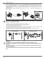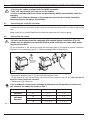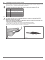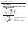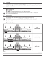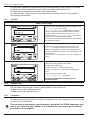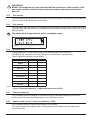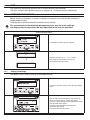
1
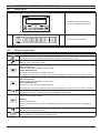
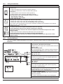
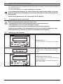
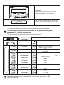
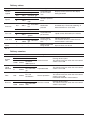
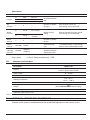
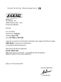
02
BRAVO 18X SERIES COMPUTERS
46718001
46718011
46718301
46718311
46718501
46718511
Software rel. 2.1X
installation, USE and maintenance
• Legend symbols
= Generic danger
= Warning
This manual is an integral part of the equipment to which it refers and must accompany the equipment in
case of sale or change of ownership. Keep it for future reference; ARAG reserves the right to modify the
specifications and instructions regarding the product at any time and without prior notice.
Contents
•
•
•
•
•
1
2
3
4
5
6
Legend symbols............................................................................................................................. 2
Foreword and use of this guide.................................................................................................. 5
Using the manual........................................................................................................................... 5
Limitations........................................................................................................................................ 5
Liability.............................................................................................................................................. 5
Product description....................................................................................................................... 6
Bravo DSB........................................................................................................................................ 6
Risks and precautions before assembly................................................................................. 6
Intended use.................................................................................................................................... 6
Contents of the package.............................................................................................................. 7
Location on the machine............................................................................................................. 8
6.1 Recommended system configuration................................................................................ 8
6.2 Locating the computer.......................................................................................................... 9
6.3 Mounting the bracket.......................................................................................................... 10
6.4 Location of the control unit................................................................................................ 10
7 Connecting the computer to the machine............................................................................. 10
7.1 General precautions for cable runs.................................................................................. 10
7.2 Power connection.................................................................................................................11
8 Connecting the cable to the control unit and services..................................................... 12
8.1 Connecting the multi-pin connector................................................................................. 12
8.2 Connecting the valves........................................................................................................ 12
8.3 Connecting the sensors and other services................................................................... 13
9 Accessory connections.............................................................................................................. 14
9.1 Foam marker........................................................................................................................ 14
10 Computer controls and display................................................................................................ 15
10.1 Control panel........................................................................................................................ 15
10.2 Using the control keys........................................................................................................ 15
10.3 Using the switches.............................................................................................................. 16
10.4 Display (delivery)................................................................................................................. 16
11 Preliminary programming.......................................................................................................... 17
11.1 Pre-programming tests and checks.................................................................................. 17
11.2 Switching on the computer................................................................................................ 17
11.3 Switching on the computer for advanced programming............................................... 18
11.4 Advanced menu................................................................................................................... 18
11.5Language.............................................................................................................................. 19
11.6 Unit of measure................................................................................................................... 19
11.7 Nr of sections....................................................................................................................... 19
11.8 Total boom width................................................................................................................. 19
11.9 Section................................................................................................................................. 20
11.10 Section valve........................................................................................................................ 20
11.11Flowmeter............................................................................................................................. 20
11.12 Tank volume......................................................................................................................... 21
11.13 Tank reserve......................................................................................................................... 21
11.14 Spraying menu..................................................................................................................... 21
continues
3
11.15 Pressure reckoning............................................................................................................. 21
11.16 Nozzle number (only if "Pressure reckoning" = YES).................................................. 21
USE................................................................................................................................................... 22
12 User programming....................................................................................................................... 22
12.1 Setting the dosage.............................................................................................................. 22
12.2 Wheel constant setting....................................................................................................... 23
12.2.1 Manual wheel constant setting......................................................................................... 23
12.2.2 Automatic wheel constant setting..................................................................................... 24
13
14
15
16
17
12.3 Selecting the wheel type (constant)................................................................................. 26
12.4 Nozzle menu........................................................................................................................ 27
12.5 Min. adjusting pressure...................................................................................................... 27
Treatment........................................................................................................................................ 28
13.1 Operating modes................................................................................................................. 28
13.2 Field selection...................................................................................................................... 29
13.3 Setting calibrated returns (control units with three-way valves).................................. 29
13.4 Job/spray rate program selection (for automatic control ONLY)................................ 30
13.5 Automatic treatment control............................................................................................... 31
13.6 Manual treatment control................................................................................................... 31
13.7 Distribution menu................................................................................................................ 32
13.8 Fault warnings (for automatic control ONLY).................................................................. 34
Maintenance / diagnostics / repairs........................................................................................ 35
14.1Troubleshooting................................................................................................................... 35
14.2 Test menu............................................................................................................................. 36
14.3 Problems due to the type of system and computer’s mode of operation..........................38
14.4 Opening the connector and swapping the wires:........................................................... 38
Technical data............................................................................................................................... 39
15.1 Units of measurement........................................................................................................ 39
15.2 Computer technical data.................................................................................................... 41
Disposal at the end of service.................................................................................................. 41
Guarantee terms........................................................................................................................... 42
4
•
FOREWORD AND USE OF THIS GUIDE
This guide includes all instructions for correct assembly, connection and set up of BRAVO 18x
family computers.
Further informations are mentioned in special installer's sheets for each computer model.
•
Using the manual
This manual contains information reserved for the installation technician, and hence makes use
of technical terminology without the explanations which would otherwise be required by the end
user.
INSTALLATION IS TO BE DONE ONLY BY AUTHORISED AND TRAINED TECHNICAL
STAFF.
THE MANUFACTURER IS NOT LIABLE FOR USE OF THIS MANUAL BY UNAUTHORIZED AND UNQUALIFIED PERSONS.
•
LIMITATIONS
All assembly steps generally refer to a Bravo computer without mentioning any model, unless a
given installation procedure specifically concerns a certain model.
•
Liability
The installation technician is responsible for implementing the installation procedure in a professional
manner so as to guarantee perfect functionality of the computer, whether supplied solely with ARAG
components or with components from other manufacturers.
ARAG recommends using its own components for the installation of the control systems.
If the installation technician should decide to use components provided by other manufacturers,
even if this should not require the modification of the cabling or other systems, he does so at his
own exclusive risk and liability.
The installation technician is responsible for compatibility with components and accessories provided
by other manufacturers.
If, as a consequence of the above recommendations, the computer or other ARAG components
installed in combination with components provided by other manufacturers should suffer damage
of any kind, no form of liability, whether direct or indirect, will be recognized by ARAG.
5
1
Product description
The BRAVO 18x computer family includes spraying computers which control all aspects of product
distribution for agricultural applications.
The computer enables the operator to control the valves and all treatment parameters, both in
automatic and manual mode.
The computers are available in a range of configurations for different numbers of sections and for
connection to various types of sensor.
The computer connects directly to the system thanks to a single cable connection to the control unit
valves and the sensors: the cab installation thus includes only the controls required for controlling
the system, giving total safety in operation.
The BRAVO computer display enables the operator to monitor all the operational data, such as the
speed of the tractor, the amount of product being distributed, the total surface area treated, etc.
2
Bravo DSB
ARAG has designed and manufactured a diagnostics system for Bravo series computers and the
systems to which they may be connected.
BRAVO DSB (article code 467003) provides reliable computer diagnostics (not of the control unit
to which it is connected) so as to enable the resolution of any potential problems experienced with
the system.
3
Risks and precautions before assembly
All installation work must be done with the battery disconnected, using suitable
tools and any individual protection equipment deemed necessary.
Use ONLY clean water for treatment tests and simulations: using chemicals during simulated treatment runs can seriously injure persons in the
vicinity.
4
Intended use
The device you have purchased is a computer which, when connected to a suitable control unit,
makes it possible to control all phases of treatment in agricultural applications directly from the cab
of the agricultural machine in which it is installed.
This device is designed to work on agricultural machinery for crop spraying applications.
The machine is designed and built in compliance with EN ISO 14982 standard
(Electromagnetic compatibility - Forestry and farming machines), harmonized with
2004/108/EC Directives.
6
5
Contents of the package
The following table lists the components contained in the BRAVO computer package:
BRAVO 18X SERIES
Legend:
1Computer
2 Instruction booklets
3 Inductive speed sensor
4 Mounting kit
5 Complete cabling for connection to the valves and sensors
6 Gaskets for section valve connectors
7 Power connector
8 Power cable
Tab. 1
7
6
Location on the machine
6.1
Recommended system configuration
Assembly diagram for crop sprayers with membrane pump
BRAVO 18x MODE "M" (CODE 46718X11)
A
B
15/54
R
+
Legenda:
S
+
-
12Vdc
A Control panel
B Starter key
S Speed sensor
F Flow meter
G Drain valve
P Control valve
R Foam marker
1-5Section valves
1 2 3 4 5 F GP
Tab. 2
Assembly diagram for crop sprayers with membrane pump
BRAVO 18X MODE "P" (CODE 46718X01)
A
B
15/54
R
+
S
+
Legend:
-
12Vdc
1 2345 F P
G
A Control panel
B Starter key
S Speed sensor
F Flow meter
G Main valve
P Control valve
R Foam marker
1-5Section valves
Tab. 3
continues
8
Continues par. 6.1 - Recommended system configuration
Assembly diagram for crop sprayers with centrifugal pump
BRAVO 18X MODE "M" (CODE 46718X11)
A
B
15/54
R
+
S
+
Legend:
-
12Vdc
A Control panel
B Starter key
S Speed sensor
F Flow meter
P Control valve
R Foam marker
1-5Section valves
1 2345 F P
Tab. 4
6.2
Locating the computer
BRAVO 18x series computers must be installed in the cab of the tractor, in observance of the
following precautions:
- DO NOT install the computer in an area subject to excessive vibration or collisions
as this may damage it or lead to its controls being accidentally actuated;
- install the unit is a visible position within easy reach by hand: bear in mind that the
computer should not obstruct the operator’s freedom of movement or block his view.
Note the connections required for the computer to operate (Tab. 5), the required length
of the cables, and provide adequate space for the connectors and cable runs.
An identification symbol is located next to each connector to indicate its function; for
the configuration of the systems, refer to par. 6.1 - Recommended system configuration.
ITEM
CABLE CONNECTION
POINTS
1
2
Control unit and Sensors
Power
Tab. 5 - 6
BRAVO 18x DIMENSIONS
Cod.
46718001 - 46718011
46718301 - 46718311
46718501 - 46718511
Fig. 1
9
Sections General Pressure
-3
5
•
•
•
•
•
•
Width A
(mm)
152
152
222
6.3
Mounting the bracket
The computer and control unit must be mounted on a bracket installed at the desired location
(the previous paragraph shows the bracket drilling template).
The bracket installs with the supplied bolts (A, fig. 2).
Make sure the bracket is securely mounted, fit the computer to it and push it in until it locks in place
(B, Fig. 2).
6.4
Fig. 2
Location of the control unit
The control unit must be installed with the special brackets supplied and mounted to the unit, positioning it as shown in the manual provided with it.
MAKE SURE TO FOLLOW ALL THE SAFETY INSTRUCTIONS GIVEN IN THE CONTROL UNIT’S MANUAL.
7
7.1
Connecting the computer to the machine
General precautions for cable runs
• Securing the cables:
- secure the cables so that they do not interfere with moving parts;
- route the cables in such a way that twisting and tractor movements cannot damage or break
them.
• Routing the cables to protect against water infiltrations:
- branches in the cable runs must ALWAYS be oriented downwards (Fig. 3).
Fig. 3
Fig. 4
• Fitting the cables to the connection points.
- Do not force the connectors by pushing too hard or bending them: the contacts can be damaged
and computer operation compromised.
• Use ONLY cables and accessories included in the part catalogue as they are technically suitable.
10
7.2
Power connection
Inside the package (component 7 - Tab. 1) you will find the power connector required for the connection to the machine’s battery; Fig. 7 shows the drilling template for installing the power connector.
Connect the power connector to the battery poles using two 6 mm faston connectors, as shown
in Figs. 5 and 6.
Use the cable provided in the package (component 8 - Tab. 1) to connect the computer to its
power supply.
Fig. 5
Fig. 6
Fig. 7
CAUTION: before powering up the computer and control unit, make sure the battery
voltage is as specified (12 Vdc).
The power supply can be connected to the unit in two ways:
• direct connection beneath the key (15/54) as shown in Fig. 8.
• connection via relay as shown in Fig. 9.
If the 15/54 contact (services) of the starter key can bear a continuous load of 10A, install the
connections indicated in Fig. 8, with a 10A fuse on the power cable.
Otherwise install a relay as indicated in Fig. 9 and install a 10 A fuse on the power cable.
Direct connection
Connection via relay
Fig. 9
Fig. 8
CAUTION:
• The power circuit must ALWAYS be fitted with a 10 Amp automotive fuse
• All battery connections must be made with cables with a minimum cross section of
2.5 mm2
To avoid short circuits, do not connect the power cable connector before the installation is completed.
• Use cables with suitable terminals to ensure correct connection of each individual
wire.
11
8
Connecting the cable to the control unit and services
• Use only the cables provided with the ARAG computer.
• Take care not to break, pull, tear or cut the cables.
• Use of unsuitable cables or cables not provided by ARAG automatically voids the
warranty.
• ARAG is not liable for damage to the equipment, persons or animals caused by
failure to observe the above instructions.
8.1
Connecting the multi-pin connector
Connect the multi-pin connector to the panel and connect the other end of its cable to the control
unit.
Make sure that it is correctly fitted and turn the collar clockwise until it locks in place.
8.2
Connecting the valves
• All valve connectors must be equipped with gaskets before installation (Fig. 10).
• Make sure the gaskets are correctly fitted to avoid infiltration of water when operating the control unit.
Fit the connectors to the valves following the markings given in the general system installation
diagram in your possession (par. 6.1 - Recommended system configuration).
Fig. 10
• Remove the protector cap (1, Fig. 10) from the electrical valve.
• Fit the gasket (2) onto the connector (3) and push the connector fully on (4): take care not to
bend the valve’s electrical contacts.
• Tighten screw (5) fully down.
If the number of control panel switches is different from the number of section valves, connect the cables as shown in Tab. 7.
COMPUTER
N. SECTIONS
SWITCHES
CABLES
46718301
46718311
2
1-3
1-3
46718501
46718511
2
2-4
2-4
3
2-3-4
2-3-4
4
1-2-4-5
1-2-4-5
Tab. 7
12
8.3
Connecting the sensors and other services
Fit the connectors following the markings given in the general system installation diagram in your
possession (par. 6.1 - Recommended system configuration).
The cables are marked to indicate the service to which they connect (Tab. 8).
ITEM
CONNECTION
S
Speed sensor
F
Flow meter
R
Foam marker
P
Control valve / / Drain valve
G
Main valve
1÷5
Section valves
Tab. 8
Use ARAG sensors: use of unsuitable sensors or sensors not provided by ARAG
automatically voids the warranty.
ARAG is not liable for damage to the equipment, persons or animals caused by failure to observe the above instructions.
- The speed sensor connection instructions are provided with the product.
- Connect the flow meter and foam marker connector to the cable connector;
check that it is inserted correctly and press it in until it locks.
Fig. 11
Fig. 12
13
9
Accessory connections
9.1
Foam marker
The foam marker ONLY operates correctly if connected to the computer with the ARAG foam marker
control kit, code 520004C.100.
All information for connecting the foam markers is given in the manual provided with the device.
Use ONLY the ARAG foam marker control kit: use of unsuitable kits or kits not provided by ARAG automatically voids the warranty in case of damage to the computer.
• Positioning the foam marker control kit
- Position the control kit in a sheltered location, near to
the pump, with its cables exiting from its base.
- Secure the device with the bolt provided in the
package.
CAUTION: if, due to limited space, the
cable has to run around a corner, make sure
that this is at least 5 cm away from the device,
as shown in Fig. 13
Fig. 13
- Route the cables in such a way that they are long
enough to reach the devices to which they are to be
connected.
- Connect the cables as indicated in Fig. 14:
R = BRAVO Computer
B = Power cable
C = Foam marker
- Secure the cables with clamps along their route.
Fig. 14
14
10
Computer controls and display
10.1
Control panel
- Computer spraying control keys.
(par. 10.2 - Using the control keys)
- Control unit valve switches
Tab. 9
10.2
Using the control keys
Control, selection and modification keys
Control key:
Resets the increment / decrement percentage of delivery value or sets its value.
Control key:
Activates the LH side foam marker.
DOWN KEY
Data selection key:
scrolls through the data fields in forwards order.
Data modification key:
decreases the value of the selected parameter.
To change the value of the parameter more quickly, hold down the key for more than three seconds
UP KEY
Data selection key:
scrolls through the data fields in reverse order.
Data modification key:
increases the value of the selected parameter.
To change the value of the parameter more quickly, hold down the key for more than three seconds
Confirm key:
confirms access to the selected menu or the modified parameter value
ON/OFF button
switches the computer ON/OFF.
ESC key:
quits the current menu.
If the modified data have not been confirmed, pressing ESC quits the menu without changing the
values.
Control key:
Activates the RH side foam marker.
Control key:
Activates/deactivates automatic distribution control.
Tab. 10
15
10.3
Using the switches
Control unit valve switches
Control valve / drain valve switch (depending on system):
Control valve:
• to open the control valve, move the switch up (led on).
• to close the control valve, move the switch down (led off).
Drain valve:
• to close the drain valve, move the switch up (led on).
• to open the drain valve, move the switch down (led off).
The references to the switch positions always as follows:
• "ON" position: switch up
• "OFF" position: switch down
Section valve switches:
normally each section valve installed on the unit has its own switch
• To open the section valve, move the corresponding switch up (led on)
• To close the section valve, move the corresponding switch down (led off)
The section valve control depend on the type of operation enabled with the computer: for full details,
refer to par. 13.1 - Operating modes
Control valve switch:
• to increase the amount of liquid to be delivered, move the switch up
manual operation: increases the amount of liquid to be delivered;
automatic operation: increases the amount of liquid to be delivered in steps of 10% of the
original setting.
• to decrease the amount of liquid to be delivered, move the switch down
manual operation: decreases the amount of liquid to be delivered;
automatic operation: decreases the amount of liquid to be delivered in steps of 10% of the
original setting.
Tab. 11
10.4
Display (delivery)
The main screen is described below: the symbols indicate the data which can be displayed during
treatment.
1 Distribution value data
• AIncrement / decrement percentage:
indicates the percentage of the variation relative to the set
delivery value.
• BDistribution value:
the actual distribution value is displayed during treatment
• CSpraying disabled: the main control switch is OFF.
2 Foam marker active side
• A LH side active
• B RH side active
3 Tank reserve status indicator:
below the set "reserve" value, the computer generates a
visual and audible warning.
4 Control valve mode
• Aautomatic
• Bmanual
5 Generic alarm symbol:
refer to the paragraph dealing with common operating
faults (13.8 - Fault warnings).
6 Operating data:
this field displays the treatment data (for example, the
speed); refer to par. 11.14 - Spraying menu.
7 Speed simulator active:
the tractor’s speed is not read by the sensor, but simulated by the computer.
The value is displayed to the right of the flashing icon.
8 Other values: Number of the field being treated.
Tab. 12
16
11
Preliminary programming
The computer can be programmed with the parameters required to ensure correct distribution of
the treatment product.
This must be done once only, when installing the computer.
In the following paragraphs, the screen shots only show the key points of the programming procedure: the display may change when the keys described in the text
are pressed.
When setting parameters, their values flash on the display.
11.1
Pre-programming tests and checks
Before programming the computer check that:
• all components are correctly installed (control unit and sensors);
• the equipment is connected to its power sources;
• all components are correctly connected (control unit and sensors).
Incorrect connections of the components and the use of other components from
those specified can damage the system or components themselves.
11.2
Switching on the computer
Switching ON (A + 1)
Turn the ignition key to ON and press the button.
The device runs a display self-test, displays the
software version, and then displays the delivery
menu.
Switching the computer OFF (B)
Press the button at any time until the screen being
displayed disappears.
Release the button; the computer will switch off
after a few seconds.
17
11.3
Switching on the computer for advanced programming
Power ON
1) With the computer switched off, hold down
the keys together and press key 2; release key 2
immediately after the device switches on.
The device runs a display self-test, displays the
software version, and then displays the advanced
menu.
11.4
Advanced menu
The advanced menu gives access to all BRAVO computer programming options.
The minimum and maximum settable values for the parameters are given in
paragraph 11.6 - Units of measurement.
The following table shows the structure of the advanced menu.
+
PARAMETER
SETTABLE DATA
Par.
Language
11.5
Units
11.6
No. of sections
11.7
Italian - English - Spanish
Portuguese - French - German
Polish - Russian - Croatian
EU
US
US TURF
1÷5
Section
(submenu - par. 11.9)
2-Ways
3-Ways
Total boom width
11.8
Section valves
11.10
Flowmeter
11.11
Value
Tank volume
11.12
Value
Tank reserve
11.13
Spraying menu
11.14
Pressure reckoning
11.15
Nozzle number
11.16
Value
Large
Short
YES
NO
1 ÷ 1000
Tab. 13
(Menu item "Nozzle number" is active) ONLY if the previous item is set to "YES"
(Pressure reckoning).
18
Value
11.5
Language
This parameter sets the computer’s display language.
Available languages are the following: Italian, English, Spanish, Portuguese, French, German,
Polish, Russian, Croatian.
11.6
Unit of measure
This parameter sets the units used to display data on the computer.
• EU = European units
• US = USA units
• US TURF = USA units (applied volume = gal / 1000 square feet)
For the list of displayable data and units of measurement, refer to paragraph
15.1 - Units of measurement.
11.7
Nr of sections
This parameter sets the number of section valves present on the control unit.
CAUTION: For computers code 46718001 and 46718011 set this value to 1.
11.8
Total boom width
• Technical headings
1A
• Section width
(section valve A)
1B
• Section width
(section valve B)
2
• Boom width
Tab. 14
continues
19
Continues 11.8 - Total boom width
This parameter represents the effective spray coverage achieved by the nozzles: for example,
if there are 3 nozzles spaced 50 cm apart, the boom section width will be 1,5 m.
The displayed value represents the sum of the section widths.
To modify the data, set the value for each individual boom section: the sum of the widths is
automatically recalculated.
11.9
Section
Boom section settings
1) Use the keys to scroll through the parameters in the
Advanced Menu and select
Total boom width, followed by its value: this
value is calculated by the computer from the widths
of each section, which can be set in the Section
submenu. The Total boom width parameter is
the sum of the individual section lengths.
2) Press the key to open the submenu to select/modify
the individual sections.
Total boom width
1+
1+
2
3) Use the keys to scroll through the sections in the
Section submenu until the section you wish to
modify is displayed: the sections are displayed at the
top right of the display, while the line below displays the
current value.
4) Press the key to confirm that you wish to modify the
value.
Section
3+
3+
4
5) Modify the section width with the keys: to change the
value more quickly, hold the keys down.
During data modification:
A) Press the key to confirm the new value.
B) Press the key once to exit without modifying the
value.
Section
6
5+
11.10
5+
A
B
6) Press the key to return to the
Total boom widht parameter.
During data modification a flashing cursor
will be displayed.
Section valve
This parameter sets the type of section valves present on the control unit:
• 2-way (valves without calibrated return)
• 3-way (valves with calibrated return)
11.11
Flowmeter
This parameter sets the flowmeter constant: this indicates how many flowmeter pulses correspond
to one unit of liquid delivered.
This constant is indicated on your flowmeter’s data plate; for ORION flowmeters only,
refer to the "Technical data" section in the flowmeter’s user manual for the value to
be entered in the computer.
20
IMPORTANT:
BRAVO 18x computers can only calculate the flow and delivery rates correctly if the
flow meter has been installed to the control unit and the flow meter constant has
been set.
11.12
Tank volume
This parameter sets the amount of liquid which can be contained by the tank: this is thus the maximum amount to which the tank can be filled.
11.13
Tank reserve
This parameter sets the "reserve" value, below which the computer generates a visual and audible
warning: when the reserve value is reached during operation, the tank symbol (Fig. 15) on the
display flashes.
The sound alarm stops when the tank is completely empty.
Fig. 15
11.14
Spraying menu
During distribution, you can display and control the treatment data in real time.
The BRAVO 18x computer can display the data in an extended or reduced menu.
Table 15 gives the displays in both modes.
DATUM
LARGE
Speed
•
SHORT
•
Pressure *
•
•
Flow rate
•
•
Area
•
•
Sprayed quantity
•
•
Treated field
•
•
Tank level
•
Time
•
Distance
•
Tab. 15
* Only if "Pressure reckoning" in Advanced menu is set to YES.
11.15
Pressure reckoning
This parameter allows the display of a pressure value as reckoned depending on flow rate
at the nozzle and shown by the flow meter in the "Distribution menu".
11.16
Nozzle number (only if "Pressure reckoning" = YES)
This parameter allows to set the total number of bar nozzles.
This setting allows Bravo 180 to reckon system pressure according to the flow rate shown
by the flow meter.
21
•
USE
This section of the manual explains how to use the BRAVO 18x computer.
The keys and their descriptions are given in Chapter 10 - Computer controls and display.
12
User programming
Before starting a treatment, a number of settings are required to ensure that the treatment is
implemented correctly.
Once the data have been entered, treatment can be started.
The screenshots in the following paragraphs cover only the main settings:
the display may change when the keys specified in the text are operated.
Access to User menu
1) Hold down the key for one second.
---- Menu -----User
---
Displays the main Menu Userscreen.
The computer now enables you to set
the treatment dosage values.
â
Rates setup
12.1
Setting the dosage
The BRAVO 18x is able to store up to 5 dosage settings:
1) Press to confirm access to the dosage settings
menu.
Keys A and B scroll through the five settings or,
when the cursor flashes, modify the value.
2) Press to enter dosage value modification mode.
The selected value flashes.
3) Press to increase/decrease the value.
4) Confirm the setting.
5) Press to exit from the menu.
Rate
A
3
B
3
2 4
5
22
Nozzle type to be matched with spray rate can be selected only if pressure reckoning is
ENABLED:
Rate
USER1
When "Pressure reckoning" is ENABLED,
nozzle type and spray rate will alternatively flash in the lower display line.
Press OK to select one of the two items.
Press UP and DOWN keys to set as
required. Press OK to confirm and go
to next item, or press ESC to quit
without saving.
1/5
If the use of customizable nozzles is required (USER1 to USER5), they can be selected without
changing their settings. To change their settings, go to Advanced menu.
12.2
Wheel constant setting
The wheel constant is the distance traveled by the tractor per speed sensor pulse. This value is used
by the BRAVO 18x to calculate the tractor’s speed and hence the dosage at a given speed.
The wheel constant depends on the type of wheel and the number of sensing points installed on it.
The BRAVO 18x can store up to 3 different wheel constants.
If the wheel on which the speed sensor sensing points are installed is changed, the
wheel constant may change.
At this point the value must be reset.
12.2.1
Manual wheel constant setting
The wheel constant can be calculated to a good approximation by measuring the distance traveled
by the wheel on which the speed sensor is installed. The longer the distance traveled, the more
precisely the wheel constant can be determined.
We recommend making the measurement with the tires inflated to their operating
pressure.
The wheel constant (WheelK) is calculated as follows:
WheelK =
distance traveled (cm)
nr. sensing points x nr. wheel rotations
where:
<distance traveled> is the distance in cm traveled by the wheel during the measurement,
<nr. sensing points> is the number of sensing points (e.g. magnets, bolts, etc.) on the wheel,
<nr. wheel rotations> is the number of rotations of the wheel over the measured distance.
Continues
23
Wheel constant calculation example:
the calculation supposes that the wheel has effected 20 rotations (over a measured distance of
7536 cm). The wheel has 8 sensing points.
WheelK =
7536
8 x 20
WheelK = 47,10
This is the value to be entered in the BRAVO 18x.
1) Press to confirm modification of the wheel constant.
2) Press to confirm the modification of the value, indicated
at the top right of the display.
Press A to select the wheel constant for the next
wheel.
3) The BRAVO 18x prompts for manual setting of the
wheel constant: press to modify the value.
Press A to set the wheel constant automatically
(par. 12.2.2).
4) Press to modify the value.
5) Confirm the new value.
6) Press twice to exit from the menu.
12.2.2
Automatic wheel constant setting
The BRAVO 18x is able to calculate the wheel constant automatically from the number of pulses
received from the speed sensor while traveling over a straight line path of:
• 100 m (EU)
• 300 feet (US - US TURF)
The setting procedure must be done on medium hard ground.
If treatment is to be done on soft or very hard terrain, the changed rolling diameter
can result in errors in delivery calculation: in this case we recommend running the
procedure again.
Automatic wheel constant setting is done by traveling over the measured distance with the tank
filled only with water, to half of its total capacity.
24
1) When the menu
Rates setup displays, select the
Wheels setup menu
2) Press to confirm modification of the wheel constant
3) Press to confirm the modification of the value, indicated at the top right of the display.
Press A to select the wheel constant
for the next wheel.
Wheel constant
Manual setup
4) The BRAVO 18x prompts for manual setting of
the wheel constant: press to set the wheel constant
automatically.
Wheel constant
Automatic calc.
4
5) Press to confirm: the display will prompt for you to
start the tractor.
Drive the measured distance: the number of pulses will
increase.
At the end of the measured distance, stop the tractor.
6) Press to terminate the procedure.
The computer will display the number of cm
(inches) traveled per pulse.
The wheel constant is now stored.
7) Press twice to return to the distribution menu.
If the display reads Error!, this means that the number of pulses received by the
computer during the automatic calibration procedure is too low to calculate the
wheel constant; this can be due to incorrect mounting of the wheel or if the sensor
is located too far away from the sensing points. Check that the sensor is correctly
mounted and repeat the procedure.
If the problem persists, contact the installation technician.
25
12.3
Selecting the wheel type (constant)
Once the wheel constants have been stored (up to 3), they can be called up as required for the
wheels in use.
1) When the Rates setup menu displays,
press twice to access the Wheel Selection
menu.
The menu will ONLY display if at least two wheel constants are stored in the computer.
2) Press to confirm access.
3) Press to select the desired "wheel type" (wheel constant).
4) Confirm the selection.
5) Press to return to the Menu Spraying.
Only the types of wheels will display for which wheel
constants have been stored in the computer.
26
12.4
Nozzle menu
This menu allows to set selected nozzles.
1) When displaying Nozzle data , menu, the following parameters will alternatively flash in the lower line:
).
- Flow rate (e.g.
).
- Pressure (e.g.
Press OK to enter the submenu.
Nozzle data
0,40 l/min.
1
ISO11001
0,40 l/min.
2) Press UP and DOWN to display ISO nozzles and all
5 customizable nozzles (USER 1 to 5).
USER1
1.37 l/min.
3) Press OK to enter submenu to set all parameters of
USER nozzles only.
USER1
Flow rate
4) Press UP and DOWN to switch from FLOW RATE to
PRESSURE: press OK to set the required parameter.
Flow rate
1.37 l/min.
5) Press UP and DOWN to set the required value
(flashing item) and then press OK to confirm and UP
and DOWN to switch to other item to be set following
the same procedure.
12.5
Min. adjusting pressure
This menu allows to set a pressure value under which Bravo 180 disables automatic adjusting
function.
This menu item is displayed only if "Pressure reckoning" in Advanced menu
is set to YES.
27
13
Treatment
Once the preliminary configurations described above have been completed, it is possible to start
the treatment in MANUAL or AUTOMATIC mode.
In the following paragraphs, the screen shots only show the key points of the setting
procedure: the display may change when the keys described in the text are pressed.
13.1
Operating modes
• Operating mode "P":
the section valves are controlled independently.
Operating the main control switch does not affect the status (open or closed) of the section
valves.
• Operating mode "M":
the section valves are opened and closed with the main control switch*, so long as the section valve
switch is appropriately positioned; in other words, if the section valve switches are set to OFF (lever
down), operating the main control switch will not affect the section valves. If one or more section
valve switches are set to ON (lever up), closing or opening the main control switch will close and
open the respective section valves as well.
* operation of the main control switch is described in par. 10.3 - Using the switches
BRAVO CODE
Sections
46718001
46718011
46718301
46718311
46718501
46718511
3
5
General
Pressure
•
•
•
•
•
•
Tab. 16
28
Mode "P"
Mode "M"
•
•
•
•
•
•
13.2
Field selection
When treating a field, the BRAVO 18x collects the data for the current job (treated surface, liquid
delivered, treatment time, distance traveled) and stores up to 4 different treatments.
These data can be called up with the "FIELD" function.
300 l/ha
Fig. 16
300 l/ha
Fig. 17
Select the field before starting a new treatment: if this is not done, the data will be
added to those for the last selected field.
13.3
Setting calibrated returns (control units with three-way valves)
Calibrated returns, fitted onto control units with three-way valves, ensure there are no pressure
variations when closing one or more section valves.
Set EACH TIME nozzle type is changed.
Please refer to user's guide supplied with purchased control unit for details on
adjusting procedure.
If nozzle type is not changed, adjustments made ensure a steady spray even in case of jobs
at different operating pressure.
29
13.4
Job/spray rate program selection (for automatic control ONLY)
Before starting treatment, select the right dosage from those provided in the Menu User (par. 12.1).
300 l/ha
9.1 Km/h
1) Hold down the key for 1 second to
enter the dosage selection menu.
1
2) Press to scroll through the dosage
settings.
3) Confirm the selection.
If pressure reckoning is ENABLED on spray rate selection,
pressure reckoning value and selected nozzle will alternately flash on the display.
Rate
30
13.5
Automatic treatment control
Refer to Chapter 10 - Computer controls and display - for information on operating
the keys and switches.
1) Press to enable automatic mode: the letter "A"
(automatic) displays.
2) Open the section valves by setting the control panel switches to the up position: their leds will turn on*.
3) Drive to the start of the field.
4) Set the main control switch up: its led will turn on.
6) Run the treatment.
300 l/ha
1
*: the leds only turn on for computers configured to operate in
P mode. If the computer is configured for M mode, the section
leds will only turn on when the main control switch is set to ON.
4
2
When treatment is run in automatic mode, the
computer keeps delivery to the set value: press the
pressure control valve switch to temporarily change
the distribution value: the value can be modified in
10% steps (in the range -50% - +50%).
This temporarily changes the distribution value:
to set a new permanent distribution value, refer to
par. 12.1 - Setting the dosage.
A) Press to increase the distribution value.
B) Press to decrease the distribution value.
Attention: when the distribution value is being
changed, the display alternately flashes the variation percentage and the current distribution value.
To return to the set distribution value, press the
RATE key.
13.6
Manual treatment control
Refer to Chapter 10 - Computer controls and display - for information on operating
the keys and switches.
1) Press to enable manual mode: the letter "M"
(manual) displays.
2) Open the section valves by setting the control
panel switches to the up position: their leds
will turn on*.
3) Drive to the start of the field.
4) Set the main control switch up: its led will turn on.
5) Operate the switch to set the desired dosage.
6) Run the treatment.
300 l/ha
M
1
*: the leds only turn on for computers configured to operate
in P mode. If the computer is configured for M mode, the
section leds will only turn on when the main control switch
is set to ON.
4
2
5
31
13.7
Distribution menu
This menu provides the treatment options. Almost all parameters have a submenu which can be
accessed by holding down the UP and DOWN keys together for 1 second; this opens the function
associated with the selected menu.
In all submenus, pressing OK confirms entry or modification of a parameter, while pressing ESC
cancels the operation or quits the menu option.
Measuring the current speed
300 l/ha
Speed
Speed simul.?
YES
NO
Simulating the tractor’s speed enables
product distribution even without a
speed sensor mounted to the wheels.
The default simulation setting is 6 kph;
this can be changed by holding down
OK and pressing the UP and DOWN
keys.
When this function is used, the
dosage cannot be the real value
inasmuch as the speed of the tractor
is not detected in real time.
THIS ITEM WILL SHOW ONLY
IF PRESSURE RECKONING IS
ENABLED
Instantaneous pressure indication
300 l/ha
Pressure
This function allows the user to read
pressure value proportional to flow rate
and selected nozzle.
Instantaneous flow rate indication
300 l/ha
Flow rate
Treated surface count
This function resets the treated surface
count for the field indicated at the right
corner of the display.
Reset?
300 l/ha
Area
YES
NO
CONTINUES
32
Liquid distributed count
Reset?
This function resets the liquid distributed
count for the field indicated at the right
corner of the display.
300 l/ha
Sprayed qty.
YES
NO
Field treated
Field selection
300 l/ha
Field
Press to select the field to be treated.
After the field selection has been
confirmed, the computer will prompt for
the operator to reset the parameters for
the selected field.
Reset?
Field data
Tank level*
Tank filling
300 l/ha
Tank level
This function fills the tank.
The computer displays the maximum
filling value, which can be changed with
the UP and DOWN keys.
Confirm by pressing OK.
Treatment time*
Press to reset the treatment time
counter for the field at the right corner
of the display.
Confirm with OK, cancel with ESC.
Reset?
300 l/ha
Time
YES
NO
Distance traveled count*
Press to reset the distance traveled
count for the displayed field. Confirm
with OK, cancel with ESC.
Reset?
Distance
YES
NO
To return to the speed display, hold down the UP key for three seconds at any time.
* this menu option is only displayed if EXTENDED menu mode is selected.
33
13.8
Fault warnings (for automatic control ONLY)
If distribution errors occur during treatment, the computer warns the operator by sounding a buzzer
and displaying a message describing the problem.
Speed alarm
The computer does not detect the tractor speed
and the control unit is supplied (control valve open
or drain valve closed).
Set the main control switch to OFF or start
the tractor.
If the tractor is already in motion, there may be
a problem with the speed sensor.
Flow rate alarm
If there is insufficient flow to the flow meter and
hence to the control unit, the computer notifies
the user (1) by display 0 flow rate (2).
1
2
Distribution alarm
If the set distribution value cannot be reached,
the computer indicates that the tractor should
speed up or slow down.
Tab. 17
34
14
Maintenance / diagnostics / repairs
14.1
Troubleshooting
FAULT
CAUSE
REMEDY
• Turn the ignition key to "Ignition".
• Check the power cable connections.
• Press the power button.
The display does not turn on No power
The valves do not respond
to controls
The valves are not connected
A valve refuses to open
No power to valve
The displayed speed is
incorrect even at constant
speed
Incorrect programming
Speed sensor signal not received
Incorrect speed sensor installation
The delivery volume display
is incorrect
Incorrect programming
The treated surface count
displayed on the computer differs from the actual
amount of terrain covered
The traveled distance count
displayed on the computer differs from the actual
distance traveled
The delivered liquid display
differs from the actual
amount of liquid delivered
Incorrect programming
The counter has not been reset
Incorrect programming
The time count display
differs from the actual
treatment time
• Check the electrical connection and functionality of the valve.
• Check the wheel constant setting (par. 12.2).
• Check the speed sensor connection.
• Check the speed sensor installation.
• Check the boom width setting (par. 11.8).
• Check the flow meter constant setting
(par. 11.11).
• Check the speed sensor installation.
• Check the wheel constant setting (par. 12.2).
• Check the section valve type setting (par. 11.10).
• Check the boom width setting (par. 11.8).
• Check the speed sensor installation.
• Check the wheel constant setting (par. 12.2).
• Reset the counter.
• Check the speed sensor installation.
• Check the wheel constant setting (par. 12.2).
The counter has not been reset
• Reset the counter.
Incorrect programming
• Check the flow meter constant setting (par. 11.11).
• Check the section valve type setting (par. 11.10).
You are using 3 way section valves
and the calibrated returns have not
been calibrated
The counter has not been reset
• Calibrate the returns.
Control valve malfunction
• Reset the counter.
• Correct the distribution value.
• Correct the boom width.
• Check the setting of the maximum pressure
valve.
• Check that the installed control valve is correct
for the system in use.
• Check the functionality of the control valve.
The counter has not been reset
• Reset the counter.
Incorrect programming
The set distribution value
cannot be obtained during
automatic operation
• Connect the connectors.
The system cannot deliver the
requested flow rate
Tab. 18
35
14.2
Test menu
This menu tests that the computer is operating correctly.
To access the menu, turn the computer on with the AUTO and RATE keys held down.
All tests are READ ONLY; the parameters cannot be modified.
Display test
Tractor battery voltage test
Switches test
Operate the switches to test that they are working correctly.
M
Control valve / drain valve switch (depending on system)
1÷5 Section valve switches
(the computer will display the actual number of sections installed)
+ / - Control valve switch
CONTINUES
36
Speed sensor input test
The frequency reading in Hz of the speed sensor displays.
Flow meter input test
The frequency reading in Hz of the flow meter displays.
Keyboard test
Press the keys to display the respective text.
Key texts:
RATE: RATE KEY
LH foam marker: TFSX KEY
OK: OK KEY
RH foam marker: TFDX KEY
AUTO: AUTO KEY
The UP, DOWN and ESC keys cannot be tested.
37
14.3
Problems due to the type of system and computer’s mode of operation
All work intended to partially or completely modify the operation of the computer or
any components connected thereto is done at the user’s full and exclusive liability.
If there is any doubt regarding alternative computer cable hookups, please contact
your nearest service center for further information.
IMPORTANT: FOLLOW INSTRUCTIONS BELOW ONLY IF PERFECTLY SURE THEY
WILL GRANT CORRECT SYSTEM OPERATION.
Inverse operation of the pressure regulation may be caused by the type of control unit and system
to which it is connected. Resolve the problem as described in the following table; if the problem
persists, contact your local service center.
Machine with centrifugal pump
Legend:
F Flow meter
P Control valve
1-5Section valves
1 2345
P
F
Swap wires 1 and 2 in the control valve connector
Tab. 19
14.4
Opening the connector and swapping the wires:
Fig. 18
Fig. 19
Fig. 20
• Unscrew the cable clamp with a small pair of pliers (Fig. 18).
• Prize the connector open with a screwdriver in the provided slot (Fig. 19).
• Slacken off the screws and swap the wires (Fig. 20).
Tighten the screws to the correct amount when securing the cables.
38
15
Technical data
15.1
Units of measurement
• Advanced menu
Datum
Min.
Max.
UM
Description
Notes
Language options:
Italian, English, French, German, Spanish,
Portuguese, Polish, Russian, Croatian.
Language
--
--
--
Display
language
Units of measurement
--
--
--
Units of measurement used to
display data
Available options:
EU, US, US TURF
Number of
sections
--
--
--
Number of section
valves installed
Available options:
1÷5
Boom width
(each section)
To display this value
set the width of each boom section
Type of section
valve
Available options:
2 way valve - without calibrated return
3 way valve - with calibrated return
Flow meter
constant
Used for calculating the flow rate
0,00
29,99
EU: m
0,0
299,9
US - US TURF:
feet
Section
valves
--
--
--
Flow meter
1
29999
Tank capacity
1
19999
Tank reserve
0
19999
US - US TURF:
gal
Type of
display of the
distribution
menu
--
--
Pressure
reckoning
YES
Nozzle
number*
1
Width of
each individual section
EU: imp/l
US - US TURF:
imp/gal
EU: l
US - US TURF:
gal
Tank capacity
EU: l
Tank reserve value
Below this value, the computer generates
a visual and audible warning
--
Determines whether
the counters are
displayed or not
Available options:
Large, Short
NO
--
Enable/disable
pressure reckoning
1000
--
Number of bar
nozzles
Tab. 20
*= only if the previous item is set to "YES" (Pressure reckoning).
39
Delivery values
Datum
Volume
applied
Speed
Pressure
Flow rate
Tank level
Field
Min.
0
Max.
1990
UM
EU: l/ha
0,0
199,9
US: gpa
0,0
199,9
US TURF: gpk
0
199,9
EU: km/h
0
199,9
US - US TURF:
mph
0,0
999,9
EU - EU-l/100m:
bar
0
9999
US: psi
0
999,9
EU: l/min
0
999,9
US - US TURF:
gal/min
0
19999
EU: l
0
19999
US - US TURF:
gal
--
--
--
Description
Notes
Liquid delivered
per unit surface
area
Displays on the first line of the display
during treatment
Vehicle’s speed of
travel
Distribution
pressure
Available only if "Pressure reckoning" in
Advanced menu is set to YES.
Liquid delivered
per unit time
Liquid actually delivered by the nozzles
Level of liquid
remaining in the
tank
Floating decimal point
The counter decreases when the main
control switch is set to ON
Number of the field
being treated
Up to 4 values can be set
Tab. 21
Delivery counters
Datum
Min.
0,000
Max.
99999
UM
EU: ha
Surface
area
0,000
99999
US: acres
0,000
99999
US TURF:
1000 square ft
0
99999
EU: l
Liquid
delivered
0
99999
US - US TURF:
gal
Time
0:01
99999
EU - US
US TURF: h
0,001
99999
EU: km
99999
US - US TURF:
miles
Distance
0,001
Description
Notes
Treated surface
Floating decimal point
The counter increases when the main control
switch is set to ON
Liquid delivered
The counter increases when the main control
switch is set to ON
Time of operation
Floating decimal point
The counter increases when the main control
switch is set to ON
From 00:01 to 99:59 in hh:mm format
Distance traveled
Floating decimal point
The counter increases when the main control
switch is set to OFF
Tab. 22
40
User menu
Datum
Min.
Max.
UM
0
600
EU: l/ha
0
600,0
US: gpa
0
60,00
US TURF: gpk
1
5
--
0
99,99
EU: cm/imp*
0
99,99
US - US TURF:
inch/imp*
Wheel
settings
1
3
--
Number of settable
wheels
Nozzle
settings#
ISO11001
USER5
--
Selected nozzle
type
Min.
adjusting
pressure#
Disabled
100.0 bar
(1450 psi)
Dosage
Set
dosages
Wheel
constant
Description
Notes
Desired distribution
rate
--
Number of settable
dosages
Up to 5 values can be set;
zero settings are not displayed
Wheel constant
setting
Used to calculate the tractor speed;
zero settings are not displayed
17 available nozzles: 12 ISO steady
nozzles and 5 customizable nozzles
Min. pressure for
disabling automatic
adjusting function
Tab. 23
*imp= pulse
15.2
#
= only if “Pressure reckoning” = YES
Computer technical data
Description
BRAVO 18x
Alphanumeric LCD display
2 lines x 16 characters, backlit
Display:
Power supply:
11 ÷ 14 Vdc
Consumption (only computer):
150 mA
0°C ÷ 60 °C
+32°F ÷ +140 °F
Working temperature:
Digital inputs:
for open collector sensors: max. 2000 imp./s
726 g
(Bravo code 46718501 without cabling)
Weight:
Protection against reversal of polarity:
•
Protection against short circuit:
•
Tab. 24
16
Disposal at the end of service
Dispose of the system in compliance with the established legislation in the country of use.
41
17
Guarantee terms
1. ARAG s.r.l. guarantees this apparatus for a period of 360 day (1 year) from the date of sale
to the client user (date of the goods delivery note). The components of the apparatus, that
in the unappealable opinion of ARAG are faulty due to an original defect in the material or
production process, will be repaired or replaced free of charge at the nearest Assistance
Centre operating at the moment the request for intervention is made.
The following costs are excluded:
- disassembly and reassembly of the apparatus from the original system;
- transport of the apparatus to the Assistance Centre.
2. The following are not covered by the guarantee:
- damage caused by transport (scratches, dints and similar);
- damage due to incorrect installation or to faults originating from insufficient or inadequate
characteristics of the electrical system, or to alterations resulting from environmental,
climatic or other conditions;
- damage due to the use of unsuitable chemical products, for spraying, watering, weedkilling or any other crop treatment, that may damage the apparatus;
- malfunctioning caused by negligence, mishandling, lack of know how, repairs or modifications carried out by unauthorised personnel;
- incorrect installation and regulation;
- damage or malfunction caused by the lack of ordinary maintenance, such as cleaning of
filters, nozzles, etc.;
- anything that can be considered to be normal wear and tear.
3. Repairing the apparatus will be carried out within time limits compatible with the organisational needs of the Assistance Centre.
No guarantee conditions will be recognised for those units or components that have not
been previously washed and cleaned to remove residue of the products used;
4. Repairs carried out under guarantee are guaranteed for one year (360 days) from the
replacement or repair date.
5. ARAG will not recognise any further expressed or intended guarantees, apart from those
listed here.
No representative or retailer is authorised to take on any other responsibility relative to
ARAG products.
The period of the guarantees recognised by law, including the commercial guarantees and
allowances for special purposes are limited, in length of time, to the validities given here. In
no case will ARAG recognise loss of profits, either direct, indirect, special or subsequent to
any damage.
6. The parts replaced under guarantee remain the property of ARAG.
7. All safety information present in the sales documents regarding limits in use, performance
and product characteristics must be transferred to the end user as a responsibility of the
purchaser.
8. Any controversy must be presented to the Reggio Emilia Law Court.
42
Confor mity Declaration
ARAG s.r.l.
Via Palladio, 5/A
42048 Rubiera (RE) - Italy
P.IVA 01801480359
Dichiara
che il prodotto
descrizione: Computer
modello: Bravo 180
serie: 46718xxx e 467110W
risponde ai requisiti di conformità contemplati nelle seguenti Direttive Europee:
2004/108/CE e successive modificazioni
(Compatibilità Elettromagnetica)
Riferimento alla Norma Applicata:
EN ISO 14982:1998
(Macchine agricole e forestali – Compatibilità elettromagnetica
Metodi di prova e criteri di accettazione)
Rubiera, 21 Dicembre 2007
Giovanni Montorsi
(Presidente)
D20127_GB-m04
12/2010
Only use original ARAG accessories and spare parts, to maintain safety conditions foreseen by the constructor.
Always refer to the ARAG spare parts catalogue.
42048 RUBIERA (Reggio Emilia) ITALY
Via Palladio, 5/A
Tel. 0522.622011
Fax 0522.628944
[email protected]
http://www.aragnet.com