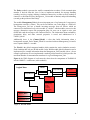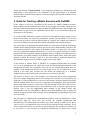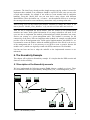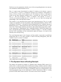
1
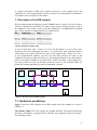
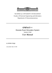
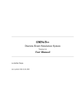
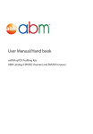
Framework for Simulation of Mobility in OMNeT++
(FraSiMO)
Heiko Scheunemann
Daniel M. Kirsch
1. Abstract
This article is an introduction as well as a reference for programmers who want to simulate
mobility in communication systems. We investigated the possibilities of simulating mobility
on the basis of the discrete event simulation system OMNeT++.
To this end we developed the "Framework for Simulation of Mobility in OMNeT++"
(FraSiMO) for OMNeT++.
FraSiMO assists the developer with fundamental classes and methods necessary for the
simulation of both nomadic and mobile wireless telecommunication systems.
On the basis of two examples we explain the main features of FraSiMO, a Dynamic Source
Routing protocoll and a nomadicity example.
1
2. Introduction
Mobility is an aspect in telecommunications which becomes more and more important. The
use of cellulars, PDA's and laptops has increased in the past years and today they are an
important part of our society. But the simulation of wireless and non-wireless mobile
communication is still a problem due to difficulties in finding and using the appropriate
simulator. Most discrete event simulation tools are originally not designed for mobility, i.e.
they use only static links between communication members.
We investigated if it is feasible to handle mobility in OMNeT++ [1], developed a concept for
handling both wireless and nomadic telecommunications and implemented a framework
supporting this concept. The framework implementation consists of a C++ library, providing
methods and features to support mobility.
The methods of the Framework for Simulation of Mobility in OMNeT++ (FraSiMO) allow
an easier link management and simple position handling. Our framework is a guideline for
design and implementation of various mobile simulation scenarios. FraSiMO is completely
written in C++ so it is not necessary to be familiar with the OMNeT++ -specific language
NED.
This paper is organized as follows:
3. OMNeT++
OMNeT++ is an object-oriented modular discrete event simulator based on C++. The main
components we have used are:
- Modules (compound and simple)
- Gates/Links
- Messages
There are two module types: “Modules that contain submodules are termed compound
modules, as opposed simple modules which are the lowest level of the module hierarchy.
Simple modules contain the algorithms in the model. The user implements the simple
modules in C++, using the OMNeT++ simulation class library.” [1].
Both module types can be connected via links. Links originate from an output gate on a
module and connect to an input gate on either the same or another module.
Messages can be send through these links from one module to another. The sending and
arrivals of messages are considered as discrete events. The receiver module becomes the new
owner of the message. It is also possible to send self-messages which are often useful for
modeling timers.
The structure of a scenario (modules, submodules and links) can be specified in a description
language called NED. However, it is possible to create all of these components during
runtime of a simulation using the OMNeT++ specific methods. For our own work we did not
use NED.
2
4. The Concept of FraSiMO
In every communication scenario there are elements that communicate with each other (in
the following we use the words communication member or subscriber for these elements).
Some of these elements can be combined to logically separable groups, for example because
they use the same channel model. These groups or clusters play an important role in
FraSiMO.
We distinguished two forms of mobile communication with regard to these clusters: First
there is movement, like a walking subscriber using a cellular (Figure 1). The communication
participant may be present in the same cluster all the time (the channel model is always the
same), but the quality of transmission changes because of variable distance, walls etc.
The other form is nomadicity (Figure 2), which means in our concept switching from one
cluster to another.
Network 1
Network 2
Host
Network 3
Figure 1: Ad-Hoc reachability
Figure 2: Nomadicity
OMNeT++ allows only bilateral relations between modules and no groups or clusters. We
had to find a way to represent such a cluster which manages nomadicity and movement
inside the cluster. So we have designed our framework with three types of modules,
described in the following.
In Figure 3 a single cluster
with 4 elements is displayed.
Handy 2
Handy 1
The elements are "linked"
together by the air interface
(cp. channel model).
Base Station
Handy 3
These elements will be
referenced in the following
as "Entities".
Figure 3: Cluster
3
The Entity module represents the mobile communication members. Each communication
member is derived from this class. It has to implement methods for message handling
(sending, receiving, copying, deleting), simulation connectivity (to allow an Entity module to
connect to or disconnect from a Management_Unit module at runtime) and position handling
(set and get the position of the Entity).
The module Management_Unit is the most important part of our framework. It represents a
homogenous network (a cluster). This can be an Ethernet, one Token Ring or a GSM cell.
The Management_Unit has to handle incoming messages from all Entities which are
connected (on simulation level) to this module. It “decides” which modules can receive this
message, determines aspects like propagation delay, bit error rate or signal to noise ratio
(SNR) and sends the message to the connected Entities. The information about reachability,
propagation delay and other network properties is stored and administered in a
Channel_Model.
Additionally there is the Channel_Model, a class that holds information about a
homogenous network. Each Channel_Model is associated with one Management_Unit and is
not a separate OMNeT++ module.
The World is the global compound module which contains the entire simulation scenario.
Each simulation has only one World module. In the World module global information can be
implemented, for example information about the Management_Units (module ids etc.). In our
example applications we have implemented a method getMaximumLoad, which provides the
maximum number of communication members for a given Management_Unit.
Figure 4, the UML diagram of our framework, shows how the components of FraSiMO fit
into the OMNeT++ architecture (white modules).
Logical View
cModule
cCompoundModule
World
cSimpleModule
Entity
+getPosition()
+setPosition()
+send()
+receive()
+connect()
+disconnect()
+redirect()
Channel_Model
+isReachable()
+getPropagationDelay()
Managment_Unit
+activity()
Figure 4: The UML-model
4
Please note that the "Channel_Model" is not completely red/dark gray, indicating that the
functionality of this module has to be redefined to fit the special needs of a particular
medium and/or communication structure. In the next chapter, the FraSiMO modules will be
discussed in detail.
5. Guide for Creating a Mobile Scenario with FraSiMO
In this chapter we will give a guideline for the creation of a mobile simulation scenario.
Some modules can have different names than in our example, all modules which must be
necessary explicitly named (because other modules of FraSiMO reference these modules) are
written italic. In some cases the explanation will be short, so we recommend reading the
description of our examples.
To create a mobile simulation scenario one first has to determine how many clusters will be
needed. Each cluster can represent a homogenous network, like an Ethernet. Yet in some
cases it may be useful to represent different parts of a network (for example the network of
one floor) as different clusters and connect them with modules representing switches.
The second step is to implement the channel model. For each cluster one has to implement a
channel model, although different clusters may use the same channel model if they have the
same physical properties. The creation of the channel model is, in most cases, very simple.
One has to implement methods which decide if a receiver can get the message of a sender
(method isReachable) and how long the propagation delay is (method getPropagationDelay).
This depends, in our DSR example, on the distance between both Entities and on the logical
channel on which the message is send. It is also conceivable to implement methods for
determination of packet error rate (PER) or signal to noise ratio (SNR).
If the creation of channel model is finished, we recommend implementing the method
activity of the management unit (while not tested, an FSM-based implementation of the
management unit may also be possible). One can use our example management unit as a
template. Each management unit has to create a gate vector. In our framework it is not
allowed to use other gates, because this will destroy the connectivity of a FraSiMO
simulation since all gates of the gate vector must have consecutive gate IDs !
The creation of Entities, like in our example, is not necessarily placed in the management
unit. Our example management unit receives messages from the gate vector (all odd id’s are
input gates). It checks which Entities can receive this message, using the method isReachable
from the channel model. For all receivers it determines the propagation delay and schedules
the message (with scheduleAt) for this time. Then the message will be sent to the receivers.
In some cases the functionality may be nearly identical to ours, so one can copy our activity
method. Only if one has implemented other methods in the channel model (like
determination of bit error rate [BER] or signal to noise ration [SNR]) one has to change the
method, so that the content of the messages will be manipulated corresponding to the packet
error rate (PER).
The next task is to implement the communication members. First one should derive a class
Mobile_Host from the Entity class and override the methods copyMessage and
deleteMessage. The management unit sends a copy of the message to each receiver, but in
some cases it is very important to copy not only the message but also the parameters. If one
wants to send each receiver its own copy of some parameters, this copyMessage method is to
be specified. It is also necessary to implement deleteMessage to destroy these copied
5
parameters. The class Entitiy already provides simple message copying, so there is no need to
implement these methods if no parameters should be copied. In some cases one may also
override other methods, for example if one wishes to create another kind of connection
handling. From this Mobile_Host one can now derive many classes with different
functionalities. These derivations can – of course – use the methods of Entity to set and get
the current position and to create and destroy connections easily to management units.
When writing your own derivations from Entities remember to change the entries in the
macro function “Module_Class_Members” to fit your derived class name and stack size.
Then one has to implement the World module. After the creation of all communication
members one knows which global information all (or many) subscribers will need. In all
cases one has to implement the method getMaximumLoad (which determines how many
Entities can connect to a given management unit). This method is necessary for the
connectivity of the Entity! One can implement other methods, for example a method which
provides a list of all management units. Unlike typical implementations with OMNeT++ we
recommend to create the Entities within the method buildInside of the World or the activity
of the management unit. It is not necessary to use NED to create a scenario, because the
module void.cc (which was originally created with NED) contains one World module.
Last but not least one has to adapt the makefile to the implemented structure or use
makemake.
6. The Nomadicity Example
This chapter will explain our Nomadicity example. It is simpler than the DSR scenario and
shows no wireless mobility.
6.1 Description of the Nomadicity scenario
We have implemented the following scenario (Table 1 shows a module overview): There
are two domains which are represented by Management_Unit_1 and Management_Unit_2.
Server_1
Host_1_1
Host_1_2
Management_Unit_1
Connector
Management_Unit_2
Server_2
Host_2_1
Host_2_2
Figure 5: The Nomadicity scenario
6
Each host can only communicate with the server of the corresponding domain, the connector
can communicate with both domain servers.
Host_1_1 wants to move from domain 1 to domain 2. It sends a switch_domain1_request to
it’s server (Server_1). Server_1 forwards this message to the Connector, which sends it to
Server_2. Server_2 sends a switch_domain1_ack via Connector to Server_1 and begins to
search for new hosts (broadcast polling). Server_1 forwards the switch_domain1_ack to
Host_1_1. This host disconnects, “travels” to domain 2 and connects. It receives a
seek_new_host from the polling Server_2, extracts the server_id from this message and
acknowledges. This is the end of this scenario.
This scenario is very specialized, but it shows some interesting aspects. First it is a good
example for nomadicity (and for the problems while displaying nomadicity with the Tcl/Tk
environment). The Host_1_1 disconnects from the Management_Unit_1 and then connects to
Management_Unit_2. The disconnection takes places using the method disconnect of the
Entity class. This method reinitializes the links to and from the Management Unit to NULL.
A new connection to a Management Unit is established with the connectWith method (class
Entity). The full description of both methods is available in chapter 7.2 . One has to consider
that the Tcl/Tk environment will not automatically update the display, so it must be done
manually with setDisplayString.
The second important aspect is the Connector, an Entity which is connected to two different
management units. It is of course possible to connect with many Management_Units, this
Connector may be a switch; for example.
ID
1
2
3
4
5
6
7
8
9
10
11
Module type
World
Management_Unit
Management_Unit
Mobile_Host
Mobile_Host
Mobile_Host
Mobile_Host
Mobile_Host
Mobile_Host
Mobile_Host
Name
Void
World
Management_Unit_1
Management_Unit_2
Connector
Server_1
Host_1_1
Host_1_2
Server_2
Host_2_1
Host_2_2
domain 1
domain 1
domain 1
domain 2
domain 2
domain 2
Table 1 Module IDs of Nomadicity example
7. The Dynamic Source Routing Example
This chapter will explain our example of a Dynamic Source Routing (DSR) scenario. In a
mobile ad hoc network [2] with wireless mobile hosts forming a temporary network without
the aid of any centralized administration or standard support services, it may be necessary for
one mobile host to enlist the aid of others in forwarding a packet to its destination due to the
limited propagation range of each mobile host's wireless transmissions. DSR is a routing
protocol for such mobile ad hoc networks. The sender creates routes on demand.
7
A complete description of DSR can be found in reference [3]. Our example may be the
substructure for own implementations. Because of this we have documented all methods of
our modules in the second part of this chapter.
7.1 Description of the DSR scenario
We have implemented the following scenario (Table 1 shows a module overview): Entity 0
wishes to communicate with Entity 4. It sends a route request (routing messages are red in
the simulation). Every Entity is able to reach his neighbors in a 4-neighborhood (cyan/light
gray). These relations are implemented in our channel model.
ID
Module type
Name
1
Void
2
World
World
3
Management_Unit Management_Unit
4-13
Mobile_Host
Ent0-Ent9
Tabelle 2 Module IDs of DSR example
A route is built (blue route - Entity: 0-1-2-3-4), but then Entity 2, a part of the route,
disconnects from the management unit (that is, it is turned off). After a timeout, Entity 0
sends another route request. After the new route is built (magenta route - Entity: 0-1-6-7-8-34), the communication continues over the new route (data messages are white in the
simulation). During the whole time Entity 4 is increasing the distance to the other Entities,
until it is no longer reachable by any other Entity. In this case Entity 0 starts polling for a
new route, but no new route can be built because the receiver is not reachable. Entity 0’s
polling will continue indefinitely or until the simulation is aborted.
Ent5
Ent6
Ent7
Ent8
Ent9
Ent0
Ent1
Ent2
Ent3
Ent4
Ent4
Figure 6: Message routes of the DSR example
7.2. The Modules and Methods
Figure 7 shows the UML diagram of the DSR example (the white modules are a part of
OMNeT++).
The Channel_Model: This class contains two member functions. The method isReachable
determines reachability, propagationDelay calculates the propagation delay for messages.
The methods in detail:
8
bool isReachable(cMessage *message, Entity *sender, Entity *receiver)
Returns true if the message from sender can reach receiver. The first criteria is the
range between sender an receiver which must not be longer than TRESHOLD, a
macro definition in channel_model.h. The other criteria is the channel of the receiver
(set with setChannelID in Entity). The method compares channel id of the message
with the channel on which the receiver listens.
double propagationDelay(Entity *sender, Entity *receiver)
Returns the propagation delay between sender and receiver, even if the sender cannot
reach the receiver. The delay is determined by distance over VELOCITY.
VELOCITY is a macro definition in channel_model.h.
Logical View
cModule
cCompoundModule
World
cSimpleModule
Entity
+getPosition()
+setPosition()
+send()
+receive()
+connect()
+disconnect()
+redirect()
Channel_Model
+isReachable()
+getPropagationDelay()
Managment_Unit
Mobile_Host
+activity()
+activity()
Routing_Package
+check_message()
+get_next_receiver_id()
+build_normal_message()
+discard_normal_message()
+build_route_request_message()
+discard_route_request_message()
+handle_route_request_message()
+discard_route_reply_message()
Figure 7: UML model of the DSR example
The Entity : This class contains the following methods.
bool connectWith(char *in, char *out, int idx)
Returns true if the Entity is successfully connected to the gates named out and in with
the Management_Unit with the module id idx. This method searchs for free gates at
the Management_Unit idx; if no gates are free, it can create new gates (if the
maximum number of communication members of this Management_Unit is not
reached). Then the method creates two connections between Entity and
Management_Unit.
cMessage *copyMessage(cMessage *msg)
Returns the pointer to a copy of the message msg.
cMessage *deleteMessage(cMessage *msg)
Deletes the cMessage msg.
9
void disconnect(char *in, char *out, int idx)
Disconnect the Entity from the Management_Unit, which is connected with the gates
named out and in. With the methods “setFrom” and “setTo” this method redirects the
connection pointers to NULL. idx is the module id of the managment unit.
void getCannelID(int *channelID)
After calling this method, id contains the logical channel on which the Entity receives.
void getPosition(int *x, int *y)
After calling this method, x contains the x-value of the position and y the y-value.
cMessage *receiveM()
Waits until a message is received. This method should be overridden if one wants to
implement new message types, e.g. with a message length or parameters like
transmission power.
void redirect(char *in, char *out, int fromidx, int toidx)
Redirect the Entity from the Management_Unit fromidx, which is connected with the
gates named out and in, to the Managment_Unit toidx. That means a disconnect from
the Management_Unit fromidx and a connectWith to the Management_Unit toidx.
void sendM(cMessage *msg, char *out)
Sends a message msg through the gate out.
protected void setCannelID(int channelID)
Sets the logical channel on which the Entity receives to channelID.
protected void setPosition(int x, int y)
Sets the position to new coordinates x,y.
The Mobile_Host: This class is derived from Entity and contains the following methods.
void activity()
The functionality of each communication member. See the scenario description.
cMessage *copyMessage(cMessage *msg)
Returns a copy of the message msg. This copied message has also a copied parameter
“source_route” and “route_record”.
cMessage *deleteMessage(cMessage *msg)
Delete the message msg and remove the parameters “source_route” and
“route_record”.
The Routing_Package:
cMessage *build_normal_message(int destination_host_id,
cMessage *message, long time)
Takes destination_host_id, a message and the current time as parameters and adds
<source_route> parameter to message, returns NULL if not possible.
cMessage *build_route_request_message(int target_id, int *request_id)
Creates a message and adds parameters <target_id>, <initiator_id>, <request_id> and
<route_record> to it and returns it.
10
int check_message(cMessage message)
Checks the message type (NORMAL, ROUTE_REQUEST, ROUTE_REPLY,
ROUTE_ERROR) and returns it.
static cArray *copyRoute(cArray *route)
Supporting method: copies the route and it’s members.
void discard_normal_message(cMessage *message)
Removes <source_route> parameter from the message and "deletes" the message
void discard_route_reply_message(cMessage *message)
Removes the parameters <source_route> and <route_record> from the message and
deletes the message.
void discard_route_request_message(cMessage *message)
Removes <route_record> parameter from the message and "deletes" the message.
int get_next_receiver_id(cMessage message)
Extracts next receiver entry from message's <source_route> returns own host-id if this
is the last entry, returns -1 if no source route was found.
cArray *getRoute(int source_host_id, int destination_host_id,
long time)
Returns the route to module id from the routing cache or null if no route exists.
Additionally this function “cleans” old entries (older than expiration time) from the
routing cache. time should be the simulation time (simTime()).
cMessage *handle_route_reply_message(cMessage *message, long time)
Takes a route reply message and extracts the route and puts it in the routing cache.
cMessage *handle_route_request_message(cMessage *message, long time)
Takes a route request message and the current time as parameters and returns NULL,
if the original message has to be discarded, otherwise it will return a route reply
message or a modified route request message.
If it returns a route reply message a check_message is needed to see if the original
message is not NULL. If this is so this has become a modified route request message
and had to be re-broadcast.
static void killRoute(cArray *route)
Supporting method: removes all elements from a route and deletes the array.
Finally there are some debugging methods, to print the different routes and the
routing cache.
The World : This class contains the method getMaximumLoad, which provides the
maximum number of communication members for the Management_Units. The connectWith
method (of Entity) creates a new connection to a Management_Unit only if this
Management_Unit has not reached his maximum number of Entities.
The method in detail:
static int getMaximumLoad(int id)
Returns the maximum number of Entities, which can be connected to one
Management_Unit. The id determines the module id of the Management_Unit.
11
8. Conclusion
With FraSiMO it is now possible to fast and easily build simulation networks intended to be
used for simulation of virtually any kind of mobility. FraSiMO enhances the basic
functionalities of OMNeT++ significantly without giving up the plain and simple structure
provided by OMNeT++. However, it does not relieve the developer of the duty of
implementing the cluster specific characteristics, like type of medium (air, cable) or the
chosen protocol architecture.
One of our main objectives was the extensibility of the framework which we have
accomplished, not only with regard to the simulation developer but also towards anyone who
wants to work with the framework itself. To improve FraSiMO we suggest implementing an
API for visualization of mobility (e.g. display of movement patterns) for the Tcl/Tk
environment of OMNeT++.
We think that FraSiMO will help you much in developing your own simulations and we hope
that you will have as much fun working with it as we had developing it.
9. References
1. András Varga
OMNeT++
Discrete Event Simulation System, Version 2.0b4
User Manual
http://www.hit.bme.hu/phd/vargaa/opp-docs/usman.htm
2. GEDOC Mobile Ad hoc Networks Study Group
What Ad hoc Networks are
http://www.siam.dcc.ufmg.br/gedoc/ad_hoc_eng.html
3. David B. Johnson, David A. Maltz
Dynamic Source Routing in Ad Hoc Wireless Networks
in Mobile Computing, Kluwer Academic Publishers, 1996
http://www.ics.uci.edu/~atm/adhoc/paper-collection/johnson-dsr.pdf
12