1
Configuring and Controlling the VP-725N
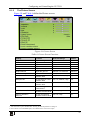
8.1.1
The Input Screen
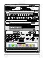
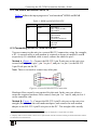
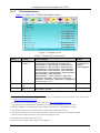
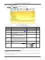
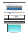
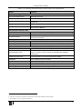
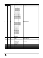
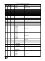
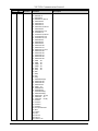
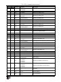
Figure 9 and Table 5 define the Input screen.
Figure 9: Input Screen
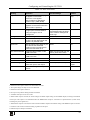
Table 5: Input Screen Functions
Setting
Function
Selection/Range
Default
Select
Select the group
Video Group, Scaler
Scaler
VGA Group
Select the VGA input 1
From 1 to 4
VGA 1
HDMI Group
Select the HDMI input1
From 1 to 4
HDMI 1
Comp Group
Select the Comp input1
YC Group
Select the YC input
CV Group
Scaler
From 1 to 4
Comp 1
1
From 1 to 4
YC 1
Select the CV input
1
From 1 to 4
CV 1
Select the source to scale
(in the Scaler operation
mode)
From VGA 1 to VGA 4; from HDMI 1 to HDMI 4;
from COMP 1 to COMP 4; from YC 1 to YC 4;
from CV 1 to CV 4, and USB
VGA 1
Image Name
Shows the file name 2 that is displayed when the USB port is connected
Color Format
Select the color format
Auto, RGB or YUV
Video
Standard
Select the video standard
Auto, NTSC, PAL, PAL-M, PAL-N, NTSC 4.43,
SECAM or PAL-60
H-Position
Set the horizontal position 3 The range changes according to the input mode
V-Position
Set the vertical position
The range changes according to the input mode
Frequency
Adjust the frequency 4
The range changes according to the input mode
Phase
Auto image
Adjust the phase
0 to 31
Assesses the image and improves the quality accordingly, by automatically
adjusting the phase, frequency and position. Upon completion, the relevant
OSD values are updated (Hpos, Vpos, Phase and Frequency)
Auto
Auto
0
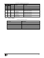
1 In the Video Group operation mode
2 Supports JPEG format only The JPEG file should not exceed a resolution of 2048x1536 If the image file is not within the
definition a blank screen appears and the machine displays the message: "File too big" or "File too small" (smaller than
320x240)
3 For UXGA and component video inputs
4 For UXGA inputs
20
KRAMER: SIMPLE CREATIVE TECHNOLOGY