1
QM-Document No.: 0101001-IM-002, Revision: B 07/2013
The V-Spec™ Monitoring System is user friendly and applies ease of use
fundamentals. Please read this operating manual carefully before starting the
system to familiarize yourself with the operation of the VSMS. All warnings
and safety instructions are listed here.
Property of Senspec. Any reproduction or copying of this operating manual is not allowed
without the written consent of Senspec GmbH.
V-Spec™ is a registered trade mark and protected by trade mark rights of Senspec GmbH .
I
II
Declaration of Guarantee
The manufacturer warrants the original purchaser of this product that each new
component of the V-Spec™ Monitoring System (see list of components) is free from
defects in workmanship and materials. Under the warranty, the manufacturer is only
obliged to replace one component which is, covered by the guarantee. at the sole
discretion of the manufacturer.
Warranty exclusion and performance of the system
The Senspec GmbH can neither warrant nor verify the performance parameters of the
device and expressly denies any warranty or liability claims in case of misuse, negligence
and damaging of Senspec products or their external damaging or if the products were not
used in accordance with the enclosed user guide or accessories were used which were not
recommended by Senspec GmbH or repairs were performed by service personnel not
authorized by Senspec.
Caution: For the United States only: Federal law restricts this device to sale on prescription
and based on FDA approval.
Patents/Registered Trade Mark/Copyright European Patent Application No.
EP2011/060337. V-Spec™ is a registered trade mark of Senspec GmbH/© 2010. All rights
reserved.
Any reproduction or copying in whole or in part of this document or its disclosure to third
parties is not allowed without the express written consent of Senspec GmbH.
Senspec GmbH has made every effort to ensure the accuracy of the information contained
in this document. Senspec GmbH denies any liability for errors or missing contents. We
reserve the right to changes on the document without prior notice.
The V-Spec™ Monitoring System is a medical device in accordance with EU guideline
93/42/EEG and complies with international standards:
IEC 60601-1, DIN EN 80601-2-61 and EN ISO 10993-1.*
*further relevant standards which were taken into account in the product manufacture can be inquired at
Senspec GmbH.
III
IV
Table of Contents
1 Range of Application and limitations................................................................................1
1.1 Range of application of the V-Spec™ Monitoring System (VSMS)..............................1
1.2 Limits of the pulse-resolved spectroscopic measurement of vital parameters..............2
2 Abbreviations...................................................................................................................5
3 Warnings and Precautions................................................................................................7
4 Safety Information...........................................................................................................9
4.1 Warnings...................................................................................................................9
4.2 Caution....................................................................................................................11
4.3 Note.........................................................................................................................12
5 VSM Symbols ................................................................................................................13
6 The V-Spec™ Monitoring System (VSMS).......................................................................15
6.1 Components and delivery........................................................................................15
6.2 Description of the monitor.......................................................................................17
6.3 Setting up the V-Spec™ Monitor (VSM)...................................................................18
6.3.1 Connection to the AC power..........................................................................18
6.3.2 Turning the VSM On and Off...........................................................................18
6.4 Connection of a V-Spec™ Sensor.............................................................................19
6.4.1 Operating the V-Spec™ Sensor with the V-Spec™ extension cable..................20
6.4.2 Application of the V-Spec™ Sensor to the measuring point of the patient......20
6.4.2.1 V-Spec™ Soft Sensor (VS-SS-L).................................................................22
6.4.2.2 V-Spec™ Sensor with Attachment Tape...................................................23
6.5 Operating the V-Spec™ Monitors............................................................................25
6.5.1 Setup and Settings..........................................................................................26
6.5.1.1 Pausing the alarm system.........................................................................26
6.5.1.2 Brightness of the screen / night mode......................................................27
6.5.1.3 Switching the screen display.....................................................................28
6.5.1.4 Main menu..............................................................................................29
Settings in the volume menu:...........................................................................30
Setting data output:.........................................................................................31
POST and reset menu:......................................................................................32
Information in the information menu:..............................................................33
6.5.1.5 Language setting......................................................................................34
6.5.1.6 Setting Date and Time..............................................................................34
6.5.1.7 Storage of the user settings......................................................................34
6.6 The Monitoring with the V-Spec™ Monitoring System.............................................36
6.6.1 Turning on the VSM........................................................................................36
6.6.2 Medical measurement parameters...................................................................37
6.6.2.1 Setting the alarm- limit.............................................................................38
Adjusting with the help of the slider:...............................................................39
Adjusting by means of the numeric keys:.........................................................39
6.6.3 Display area trend graphs................................................................................40
6.6.3.1 Trend graphs............................................................................................40
V
6.6.3.2 Plethysmogram........................................................................................42
6.6.4 Heart symbol...................................................................................................42
6.6.5 Technical parameter display area.....................................................................42
6.6.6 Alarm Indicator field........................................................................................42
6.6.7 Message system..............................................................................................43
6.6.8 Power status....................................................................................................43
6.6.9 Sensor status...................................................................................................45
6.6.10 Operation with the V-Spec™ Sensor..............................................................47
6.6.10.1 The measurements.................................................................................47
7 Alarms and Messages.....................................................................................................49
7.1 Introduction.............................................................................................................49
7.2 Alarms.....................................................................................................................50
7.2.1 Acoustic Alarm Indicators................................................................................50
7.2.2 Visual Alarm Indicators....................................................................................51
7.2.3 Alarm Limits....................................................................................................52
7.2.4 Alarm messages..............................................................................................52
7.2.5 Required Responses.........................................................................................54
7.3 Alarm-System-Reset.................................................................................................56
7.4 Alarms in the past....................................................................................................56
7.5 Alarm triggering.......................................................................................................56
7.6 Alarm Log................................................................................................................58
8 Data Communication.....................................................................................................59
8.1 Overview..................................................................................................................59
8.2 Data protocol...........................................................................................................60
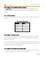
8.2.1 Serial data interface.........................................................................................60
8.3 V-Spec™ Link communication protocol....................................................................61
8.3.1 Interface settings.............................................................................................61
8.3.2 V-Spec™ Link data transfer...........................................................................61
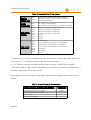
8.3.3 Layout of the header and the data arrays........................................................61
8.3.4 Status Code.....................................................................................................63
9 Technical description......................................................................................................64
9.1 Environment, Transport and Storage Conditions.......................................................64
9.1.1 Transport / Storage Conditions........................................................................64
9.1.2 Operating Conditions......................................................................................64
9.2 V-Spec™ Monitor (VSM)..........................................................................................64
9.2.1 Physical Characteristics....................................................................................64
9.2.2 Display.............................................................................................................65
9.2.3 Connections....................................................................................................67
9.2.4 Electrical characteristics...................................................................................67
9.2.5 Voltage supply.................................................................................................68
9.2.5.1 Mains operation ......................................................................................68
9.2.5.2 Battery mode ..........................................................................................69
9.3 V-Spec™ Sensors.....................................................................................................70
VI
9.3.1 V-Spec™ Soft Sensor Large ............................................................................70
9.3.2 Physical characteristics.....................................................................................70
9.3.3 Sensor temperature.........................................................................................71
9.3.4 Operating time................................................................................................71
9.3.5 Patients...........................................................................................................71
9.3.6 Permissible measuring points...........................................................................71
9.3.7 Measurement principle....................................................................................72
9.3.8 Digital microtechnology...................................................................................72
9.3.9 Sensor memory...............................................................................................72
9.3.10 Sensor temperature monitoring.....................................................................72
9.3.11 Sensor calibration..........................................................................................72
9.3.12 Characteristics of the Sensor-LED...................................................................73
9.3.13 Safety............................................................................................................73
9.3.14 Biokompatibility.............................................................................................73
9.4 Attachment Tape for V-Spec™ Sensors....................................................................74
9.5 System Performance.................................................................................................74
9.5.1 Arterial oxygen saturation (SPO2; arterial).......................................................74
9.5.2 Pulse rate (PR)..................................................................................................75
9.5.3 Tissue oxygen saturation (StiO2; tissue)...........................................................75
9.5.4 Pulsation Index (PI)...........................................................................................75
9.5.5 Pleth Index (PLI)...............................................................................................76
9.5.6 Validation........................................................................................................76
9.6 System reliability.......................................................................................................76
9.6.1 Power-on self-test (POST).................................................................................76
9.6.1.1 Internal battery for the wall clock time.....................................................77
9.6.1.2 Loudspeaker test......................................................................................78
9.6.1.3 Display Test..............................................................................................78
9.7 Alarms and messages...............................................................................................79
9.7.1 Alarm volume..................................................................................................79
9.7.2 Alarm melodies...............................................................................................80
10 Troubleshooting...........................................................................................................83
10.1 Troubleshooting for the monitor............................................................................84
10.2 Sensor-specific troubleshooting ............................................................................85
10.3 VSM specific troubleshooting.................................................................................85
11 Maintenance................................................................................................................87
11.1 Routine tests..........................................................................................................87
11.2 Service...................................................................................................................88
11.2.1 Fuse change..................................................................................................88
11.3 Cleaning and disinfection ......................................................................................90
11.3.1 Recommended cleaning and disinfection methods .......................................91
11.3.1.1 Basic principle........................................................................................92
11.3.1.2 Pretreatment..........................................................................................92
11.3.1.3 Manual cleaning and disinfection...........................................................92
VII
Cleaning /disinfection methods of the VSM.....................................................93
Cleaning /disinfection methods of sensors.......................................................93
11.3.1.4 Check....................................................................................................93
11.4 Shipment instructions for the VSMS.......................................................................93
VIII
1 Range of Application and limitations
1 RANGE OF APPLICATION AND LIMITATIONS
1.1 Range of application of the V-Spec™ Monitoring System (VSMS)
●
The V-Spec™ Monitoring System (VSMS) – consisting of the V-Spec™ Monitor
(VSM), the V-Spec™ Sensors and accessories is intended for the continuous and
non-invasive patient monitoring.
●
The basis for the V-Spec™ Monitoring System (VSMS) is the powerful, clinically
proven V-Spec™ Technology which is intended for use in adults and children over
20 kg body weight in accordance with the information contained in the sensor
package insert.
●
The V-Spec™ Soft Sensor (REF VS-SS-L) and the V-Spec™ Sensor (REF VSS) are
intended for use with the V-spec ™ Monitor if a continuous and non-invasive
monitoring of vital parameters is necessary.
●
The monitoring parameters are oxygen saturation (arterial) (SPO2), pulse (PR), tissue
oxygen saturation (StiO2), pulsation index (PI) and Pleth index (PLI).
●
The VSMS is intended for use in hospitals, hospital-type facilities, transport within
the hospital.
●
The VSMS may be operated by doctors, nurses and trained nursing staff.
●
The VSMS is only to be used on a medical prescription.
Caution: The VSMS measures the functional oxygen saturation.
Note: The use in the hospital includes operating theaters, specialist departments,
emergency and intensive care units and wards.
Hospital-type facilities include surgery centers, special care facilities and special sleep
facilities outside a hospital. Internal transportation means patient transport within
Page 1
1 Range of Application and limitations
the hospital or the hospital-type institution.
Note: In the course of x-ray examinations or CT the sensor can remain on the
patient but is then visible on the images. The sensor should be removed with the
MRI.
1.2 Limits of the pulse-resolved spectroscopic measurement of vital
parameters
The VSMS measures the vital parameters of arterial blood and the tissue. The following
clinical situations or factors may affect the readings:
●
Poor blood circulation, e.g. as a result of low cardiac index, shock, hypothermia or
proactively blood pressure titration Drugs.
●
Quality of the skin and subcutaneous tissue (e.g. direct placement over veins,
damaged skin, edema, moles or a very strong subcutaneous fat layer).
●
Poor contact between the sensor and the skin, where the light passes through the
point of input of light and the point of output of light and thereof light can pass
light directly from the light source to the spectrometer unit.
●
Intra vascular dyes. Not all dyes are included in the analysis and can thus affect the
chemo metric blood and tissue analysis.
●
Low perfusion at the measuring point, e.g. by mechanical pressure or local
hypothermia of the measuring point or part of the vascular system, which supplies
the measuring point ("cold fingers")
●
Skin pigmentation or tattoos. The usual skin pigmentation by Melanin is taken into
account in the evaluation, since the spectral analysis is carried out on the 2nd
derivation.
●
Page 2
Severe anemia.
1 Range of Application and limitations
●
Strong ambient light.
●
Arterial-venous shunts.
Warning: For the measurements the tissue is heated in the measurement volume,
which sometimes may result into an increase in the perfusion and a related increase
in the tissue oxygen saturation. Wait with a therapy or a diagnostic evaluation of the
parameters until this physiological stabilization phase is completed.
Note: The VSMS is not a blood gas analyzer. The above-mentioned restrictions must
be included in the interpretation of the values.
Note: If you compare the readings displayed on the VSM with values of arterial or
venous blood gas analysis (BGA), pay attention to the following points:
●
Carefully take and handle blood samples.
●
Blood collection should be done in the "steady state".
●
Measurement values which are determined from the BGA must be compared with
the values of the VSM at the time of the blood sample.
●
Make sure that the blood gas analyzer operates correctly.
Note: Techniques for the measurement of arterial oxygen saturation - including
pulse oximetry - cannot determine hyperoxemia. Here tissue values can allow
conditional inferences.
Note: Because of the S-shape of the oxygen dissociation curve (ODC), pulse
oximetry abnormalities of breathing in patients can not be reliably detected under
oxygen administration.
Page 3
1 Range of Application and limitations
Page 4
2 Abbreviations
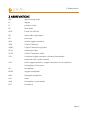
2 ABBREVIATIONS
LED
light-emitting diode
O2
oxygen
PI
pulsation index
PLI
Pleth Index
POST
Power-On Self-Test
RO
responsible organization
PR
pulse rate
SaO2
arterial oxygen saturation
VSM
V-Spec™ Monitor
VSMS
V-Spec™ Monitoring System
AT-VS
Attachment Tape
VS-EC
V-Spec™ extension cable
SPO2
functional oxygen saturation of arterial hemoglobin
measured with a pulse oximeter
StiO2
tissue oxygen saturation, oxygen saturation of the measured
hemoglobin of the tissue
Hb
hemoglobin
HbO2
oxygen hemoglobin
HHb
hydrogen hemoglobin
H2O
water
ctHb
hemoglobin concentration
HCT
hematocrit
Page 5
2 Abbreviations
Page 6
3 Warnings and Precautions
3 WARNINGS AND PRECAUTIONS
Special warnings
Please read this owner's manual carefully and follow all instructions, warnings and
precautions! The VSM must be carried out by health care professionals and be operated
without prior training by Senspec. Conditions for the proper use of the VSMS are general
knowledge of pulse oximetry, spectroscopic blood gas analysis and an understanding of the
characteristics and functions of the device.
Risk of electric shock:
●
Do not attempt to open the unit and possibly perform the maintenance yourself. If
repairs or modifications to the device are performed by persons not authorized by
Senspec, the warranty will be voided.
●
The battery cannot be exchanged by the user
●
Do not immerse the V-Spec™Monitoring System in liquids - Electric shock hazard!
●
Only connect equipment intended for the system and described in chapter 9.2.3
Connections . Follow all warnings and operating instructions enclosed with your
system! The V-Spec™ Monitoring system only works with the V-Spec™ Sensors or
V-Spec™ Soft Sensors delivered by Senspec. Do not connect sensors of other
manufacturers, the device could be destroyed. If the device is damaged due to
connection of devices or sensors not intended for the use the warranty will be
voided.
Risk of explosion::
The V-Spec™ Monitoring System must not be operated in the presence of flammable
anesthetics or other highly flammable substances.
Page 7
3 Warnings and Precautions
Risk of cross-contamination:
Clean the sensor carefully before each use, as described in the User Guide for the sensor.
Only manual cleaning / disinfection procedures are permitted. For this purpose, use running
water or an aldehyde-free disinfectant. If the V-Spec™ Sensor is used in conjunction with
the attachment tape (Ref: AT-VS) it should be noted that the AT-VS is for one-time use only
and must not be reused.
The V-Spec™ Monitoring System (not even parts of it) should not be cleaned in an
ultrasonic bath, autoclaved, gas sterilized or steam sterilized.
Risk to the patient:
The V-Spec™ Sensor and V-Spec™ Soft Sensor are intended for external use only. Please
note the enclosed instruction for each sensor and never use the sensors for internal
applications!
●
Make sure that all connections are tight and free from grease and moisture. The
ingress of moisture can lead to incorrect or inaccurate readings.
●
Be careful when attaching and removing the V-Spec™ Sensor with the Attachment
Tape (AT-VS). The AT-VS may be used only on intact and fully developed skin.
Page 8
4 Safety Information
4 SAFETY INFORMATION
4.1 Warnings
This icon indicates a warning. Warnings alert you to conditions that can lead to risks
or injuries to the patient or a user.
Warning: The V-Spec™ Monitoring System (VSMS) may only be operated by
qualified personnel. This manual, accessories instructions for use, all precautions
information and specifications should be read before use.
Warning: The V-Spec™ Monitor (VSM) is not intended for the diagnosis. It is
intended only as a supplement to the assessment of the patient's status. The VSMS
is a non-invasive pulsatile spectrometer and no blood gas analyzer.
Warning: Lay and secure the cables carefully so that the patient can not get caught
in it.
Warning: In order to ensure the safety of the patient, place the monitor so that it
cannot fall on the patient and the patient cannot be hurt!
Warning: Do not move the monitor by pulling or lifting by the sensor cable or
power cable. The cable connections can become loose and the device can fall on
the patient and harm him.
Warning: Do not spray or pour liquids on the VSM, accessories, connectors,
switches or openings in/on the housing.
Warning: If the VSM accidentally becomes wet, it must be dried before use and
inspected by a qualified service employee.
Warning: Keep the VSMS (like all the other accessories) out of the reach of children.
Risk of ingestion or risk of injury!
Page 9
4 Safety Information
Warning: Risks of explosion and flammability. Do not use the VSMS in the presence
of flammable anesthetic agents / gases or other flammable substances or in
environments with increased oxygen content.
Warning: The VSM is protected against electrostatic / defibrillator discharge.
However, it is possible that the parameter display fails temporarily during the
discharge / defibrillation, and the values are unreliable of up to 20 seconds after
defibrillation. Follow the instructions in the user's manual of the defibrillator!
Warning: During electro-surgery, the VSM, sensor and lines have to be physically
separate from the electrosurgical devices. The sensor must not be placed between
the cutting electrode and the counter electrode. The measured values can be
influenced by the electro-surgery and can be unreliable up to 20 seconds after the
end of the electro surgery.
Warning: For the protection of patients, operators, and the devices only original
cables, sensors, connectors and connections distributed by Senspec may be used!
Warning: The impact on patient safety and the performance of the VSM during a
diagnostic procedure of a magnetic resonance imaging (for example, CT, MRI) are
not known. Remove therefore during such procedures, the sensors and cables that
are connected with the VSM, from the patient!
Warning: During normal operation (except transport) it is recommended that the
monitor is always connected to the electrical outlet. The VSM must be connected to
a grounded (3-wire) electrical outlet. Make sure that the lines of the power and
ground wires are properly connected.
Warning: For the United States, or Japan: A reliable grounding can only be achieved
if the VSM is connected to an equivalent receptacle, marked with HG (hospital
grade) or HGJ (Hospital Grade Japan).
Page 10
4 Safety Information
Warning: This equipment has been tested and found to comply with the
requirements for medical devices in accordance with the requirements of IEC
60601-1, ISO 80601-2-61 and the Council Directive 93/42/EEC. These requirements
are designed to provide reasonable protection against harmful interference in a
typical medical installation.
Warning: Certain types of mobile telecommunications equipment could interfere
with the operation of the VSM. Therefore, mobile devices should not be used within
five meters (16.4 feet) of the VSM.
4.2 Caution
This symbol indicates a caution statement. Warning statements relate to conditions
that lead to damage or malfunction of the device.
Caution: Neither immerse the VSM nor the connections or accessories in liquid
solutions.
Caution: The parts of the VSM must not be sterilized by irradiation, steam, ethylene
oxide and H2O2 plasma. Follow the instructions for cleaning in the corresponding
manuals.
Caution: If the VSM with not fully charged battery is connected to an AC power
source which is interrupted or not delivering power, the monitor will not function or
shut down after a short period of time. Always pay attention to the state of charge
of the battery!
Caution: Make sure that the VSM is properly grounded, if the device is operating on
AC power. If you are unsure whether the outlet is properly grounded, disconnect
the VSM from the electrical outlet and use the VSMS in battery mode. Contact a
qualified electrician to have the outlet examined.
Page 11
4 Safety Information
4.3 Note
This symbol indicates notes, which you should consider in the use of the VSMS, in
order to ensure a smooth operation. The failure to comply with the instructions
does, however, not lead to adverse effects on the patient, the operator, or the
VSMS.
Page 12
5 VSM Symbols
5 VSM SYMBOLS
The following symbols are printed on the back of the VSM:
Symbol
Name
Description
Consult instructions for use
Please pay attention to the accompanying
documents!
Catalog number
Indicates the catalog description.
Serial Number
Indicates the serial number of the device.
Date of manufacture
Specifies the year of manufacture.
Potential balance
Connection for potential balance (ground)
Type BF defibrillator protected
Degree of protection against electric shock:
Type BF – DEFIBRILLATION, applied part
Fuse
Indicates the fuse type.
Degree of protection against
Degree of protection against ingress of water;
ingress of water; type IPX1
type IPX1: Splash-proof
CE-marking
CE declaration for the device
Caution
Security related information is included in the
enclosed documents.
WEEE old device disposal
The consumer must dispose waste equipment
(Waste Electrical and Electronic Equipment
WEEE)according to the European waste
legislation following the WEEE Statement:
Do not dispose with household waste! Use the
appropriate collection points!
Page 13
5 VSM Symbols
Page 14
6 The V-Spec™ Monitoring System (VSMS)
6 THE V-SPEC™ MONITORING SYSTEM (VSMS)
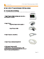
6.1 Components and delivery
The V-Spec™ Monitoring System (VSMS) contains the following main components:
• V-Spec™ Monitor (VSM) including power cord with a
country-specific connection
• V-Spec™ Sensor
•
V-Spec™ Soft Sensor (VS-SS-L) and / or
•
V-Spec™ Sensor (VSS)
• V-Spec™ extension cable (VS-EC)
• V-Spec™ Sensor Attachment Tape (AT-VS)
• VSMS manual (country specific)
• VSMS Manuals on CD (with full information, , VSM
technical manual in English only, instructions for the use of
V-Spec™ Sensors and Accessories etc. )
Page 15
6 The V-Spec™ Monitoring System (VSMS)
Verify the products for completeness and any external damage. If you should detect
damage or defects despite careful processing and packaging by Senspec, do not plug in
the appliance and contact the customer care of Senspec. We provide an easy and quick
replacement or repair.
Further instructions on operating the V-Spec™ Sensors are available in the respective
operating instructions. In order to ensure an error-free operation of the VSM, please follow
the instructions in this manual.
Note: The components listed above are not necessarily also included in the delivery.
A complete list of all available articles including accessories and supplies can be
found on the Senspec website www.senspec.com.
Note: In the following, only the V-Spec™ Sensor will be addressed. Thereby it is
expressly referred to all models of the V-Spec™ Sensor.
Page 16
6 The V-Spec™ Monitoring System (VSMS)
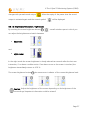
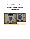
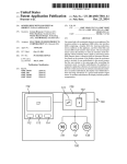
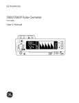
6.2 Description of the monitor
Front view:
1
handle
2
display area medical parameters
3
display area trend graph
4
heart symbol
5
speaker
6
display area technical parameters
7
display area status indicators /
change of language
8
sensor socket
9
display area settings
10 display area spectra
Rear view:
11 VESA mount mounting
sockets
12 fuse box
13 power connector
14 power switch
15 ground connection
16 type plate
Right side view:
17 RS232 connector (male)
Page 17
6 The V-Spec™ Monitoring System (VSMS)
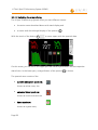
6.3 Setting up the V-Spec™ Monitor (VSM)
6.3.1 Connection to the AC power
Connect the monitor to the power source, by inserting the appliance plug of the power
cord into the socket 13 on the rear of the unit and the mains plug of the power cord into
a properly grounded power source. Use only power outlets that meet the requirements for
hospitals. The V-Spec™ system requires 100-240VAC / 50 or 60Hz..
The charging of the internal battery is done with the power supply. A fully charged battery
allows an operating duration of approximately one hour. When the device is switched on
the battery indicator informs you about the battery charge level. Full charging of a
discharged battery can take up to 4 hours.
Caution: Charge the battery fully before initial start-up!
The connection for a ground (earth pin) 15 offers if needed a redundant connection to the
external ground conductor.
6.3.2 Turning the VSM On and Off
The power switch 14 turns the monitor on and off. When you turn on the VSM, first of
all, the fan can be heard. After about 30 seconds the VSM is ready for operation.
Turning off the VSM is carried out in any case by flipping the power switch 14 to the „0“position. If the system was shut down after a "Critical battery" alarm the power cord must
be connected to power up the system. A repeated flipping of the power button is not
necessary. The settings made by the user remain partially intact as explained in chapter 7.3
Alarm-System-Reset in more detail.
Page 18
6 The V-Spec™ Monitoring System (VSMS)
6.4 Connection of a V-Spec™ Sensor
Connect the sensor plug to the socket 8 on the VSM. Make sure that the flat side of the
plug securing points upwards and the connector clicks into place. Check the sensor status
with the help of the sensor status indicator on the screen of the powered-on VSM 7.4 . To
remove the sensor, push the plug securing and gently pull the connector from the device.
Caution: Use only genuine V-Spec™ Sensors! By connecting other (i.e. third party)
sensors the connection and the system can be damaged. Senspec guarantees a
proper function of the system only if genuine equipment is connected. The VSpec™ Monitoring System is only tested with V-Spec™ Sensors.
Caution: Make sure not to twist the connector plug while connecting. The plug
must be plugged in or removed straight and not with excessive force.
Caution: Damaged, defective or modified sensors must not be used. Make sure that
the sensor cables are undamaged. If the cables show damage, they must not be
used. In this case contact your Senspec dealer or service personnel authorized by
Senspec.
Caution: Do not immerse sensor and the sensor cable into water, detergents or
solvents. Sensors must not be cleaned by irradiation, autoclave, or sterilization.
Please note the cleaning instructions in the manual for sensors and follow them.
Page 19
6 The V-Spec™ Monitoring System (VSMS)
Prior to first use and with each patient the V-Spec™ Sensor should be cleaned as described
in the User manual for the sensor. Only manual cleaning / disinfection procedures are
permitted. If you are using the V-Spec™ Sensor with the Attachment Tape (AT-VS) it should
be noted that the attachment tape is intended for single use and a new tape must be used
for each new placement of the sensor. The V-Spec™ Sensor and the V-Spec™ Soft Sensor
are suitable for repeated use.
Note: Die operating life of the V-Spec™ sensors is limited. Please refer to the
instruction manual of the sensor for more information!
6.4.1 Operating the V-Spec™ Sensor with the V-Spec™ extension cable
If an extension of the sensor cable is necessary, the original V-Spec™ Extension Cable can
be coupled between the sensor and the monitor. The connection of the connector of the
V-Spec™ Extension Cables (VS-EC) is done in the same way as of the V-Spec™ Sensor.
Caution: Use only genuine V-Spec™ Extension Cable! By connecting other (i.e. third
party) cable extensions the connection and the system can be damaged. Senspec
guarantees a proper function of the system only if genuine equipment is connected.
The V-Spec™ Monitoring System is only tested with V-Spec™ Extension Cable as
cable extension!
6.4.2 Application of the V-Spec™ Sensor to the measuring point of the
patient
Before you start with the monitoring on the patient, it's important that you become
familiar with the operation of the VSM. Check the sensor status with the help of the sensor
status indicator on the screen of the powered-on VSM 7.4 .
The following instructions must be strictly consider when using all V-Spec™ Sensors. A
correct measurement can only be carried out if all instructions are followed.
Page 20
6 The V-Spec™ Monitoring System (VSMS)
Warning: The operation of the V-Spec™ Sensors is only approved for adults and
children with more than 20kg of body weight.
Warning: Do not leave the sensor longer than 72 hours at the measuring point. Is a
longer monitoring necessary, change the Attachment Tape and, where appropriate,
the application site. In the case of non-compliance it can lead to redness of the skin
or skin inflammation. Should the skin show redness or inflammation, remove the
attachment tape, and if necessary, select a new application site.
Warning: Make sure the sensor is not covered. The sensor could heat up and cause
burns.
Warning: Make sure that the sensor cable is not wrapped around the patient's neck
or comes to a rest there, to avoid the potential risk of asphyxiation and choking.
Warning: Avoid pressure sores! Do not apply external pressure on the sensor due to
too tight band-aids, too tight bandage or a too tight headband. The measurement
results could be distorted. Secure the sensor cable with the help of a strain relief in
order to avoid that the optimal sensor seating is affected.
Caution: At the same time as the V-Spec™ Sensor EEG and devices to monitor
consciousness can be used. Attention should be paid that the optical unit of the
sensor is not affected.
Maintenance of the sensors: Please note the relevant care instructions in the owner's
manual of the respective sensor. Only manual cleaning / disinfection procedures are
permitted. For this purpose, use running water or an aldehyde-free disinfectant. If you are
using the V-Spec™ Sensor with the Attachment Tape (AT-VS) it should be noted that the
attachment tape is intended for single use and a new tape must be used for each new
placement of the sensor. The V-Spec™ Sensor and the V-Spec™ Soft Sensor are not
suitable for repeated use. For more information, please see the user manuals for the sensor
and for the Attachment Tape.
Page 21
6 The V-Spec™ Monitoring System (VSMS)
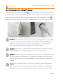
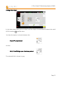
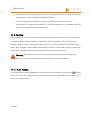
6.4.2.1 V-Spec™ Soft Sensor (VS-SS-L)
Select an appropriate measuring point for the V-Spec™ Soft Sensor Large (VS-SS-L). The
index finger is ideal. Alternatively, the thumb and the other fingers are suitable as a
measuring point.
Clean the application site (the finger) with a tested and approved disinfectant and dry it
thoroughly. Make sure that the patient's skin is completely intact, dry and free from
grease!
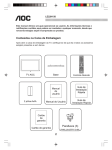
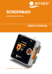
Apply the V-Spec™ Soft Sensor as described in the owner's manual of the sensor! Run the
sensor wires to the fingers and along the arm and fix it if necessary with a plaster strip.
The following figures show a correctly applied V-Spec™ Soft Sensor:
Page 22
6 The V-Spec™ Monitoring System (VSMS)
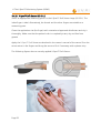
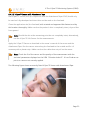
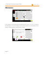
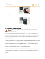
6.4.2.2 V-Spec™ Sensor with Attachment Tape
The V-Spec™ Sensor (VSS) (in conjunction with the Attachment Tape AT-VS) should only
be used on fully developed and intact skin and be used on the forehead.
Clean the application site (the forehead) with a tested and approved disinfectant and dry
this location thoroughly. Make sure that the patient's skin is completely intact, dry and free
from grease!
Note: Should the skin at the measuring point be not completely intact, alternatively,
use the V-Spec™ Soft Sensor for the measurements.
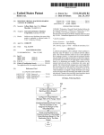
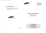
Apply the V-Spec™ Sensor as described in the owner's manual of the sensor and the
Attachment Tape. Run the sensor wires along the forehead to the outside and fix it if
necessary with a plaster strip. Make sure that the cable does not pull on the sensor.
Note: Check the fit of the sensor and the quality of the measurement with the
technical parameters displayed on the VSM "Pulsation Index PI". A low PI-value can
point to a sensor not correctly applied.
The following figure shows a correctly fitted V-Spec™ Sensor with Attachment Tape.
Page 23
6 The V-Spec™ Monitoring System (VSMS)
Warning: The Attachment Tape is for one-time use and must be replaced after each
use. Use a new tape for each measurement and each patient! Re-use can lead to
cross-contamination, poor application and thus result in inaccurate readings. Use
the Attachment Tape only on intact and fully developed skin.
Warning: Use only original accessories for the V-Spec™ system. Secure the sensor
only with the corresponding AT-VS of Senspec. The use of other than the
recommended fasteners can result in inaccurate readings.
Warning: Make sure that the attachment Tape is well secured to the sensor and is
completely applied on the application site of the patient! Change the AT-VS, if it is
not fitting tight! The failure to do so could result in inaccurate readings.
Warning: Remove the sensor and the Attachment Tape carefully and gently! If it is
difficult to remove please follow the hospital's policy on the conservation of the
integrity of the skin! Where required, use commercially available non-irritating
solvent for adhesive tape!
Note: In dark-skinned patients, it is possible that the skin is not detected and the
sensor is displayed as not applied. In this case use the V-Spec™ Soft Sensor for
measurements.
Note: It can happen that the sensor detects skin and the sensor appears as applied
even though the sensor was not applied (e.g. if sensor lies on clothes). Always apply
the sensor first on the patient before you connect it to the VSM!
Page 24
6 The V-Spec™ Monitoring System (VSMS)
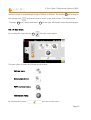
6.5 Operating the V-Spec™ Monitors
2
Display area medical parameter:
2.1
2.2
2.3
4
3
Display area trend graphs:
SPO2-value
PR-value
StiO2-value
3.1
3.2
3.3
Heart-symbol
6
Display area technical parameter:
6.1
6.2
7
Display area status indicators:
7.1
7.2
7.3
7.4
7.5
10
Alarm indicator field
Message system
Power-status
Sensor-status
Date and time
9
trend graph field 1
trend graph field 2
trend graph field 3
Pulsation Index
Pleth Index
Display area settings:
9.1
9.2
9.3
9.4
9.5
Alarm pause button
Screen brightness button
Spectral view button
Main menu
Language setting
Display area spectra:
10.1
10.2
10.3
Pulsatile absorption spectrum
Extracted blood spectrum
Tissue spectrum
Page 25
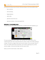
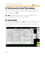
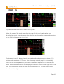
6 The V-Spec™ Monitoring System (VSMS)
The main screen consists of several different areas. These include in the upper area the real
time values of the parameters SPO2, PR and StiO2 2 , the trend curves 3 in the central
area, the heart symbol in the lower left corner 4 , the values of the technical parameters PI
and PLI 6 on the bottom of the screen, the display area with the status indicators 7 at
the bottom right (on the top of the left site the language setting), the menu bar 9 on the
right side and the display area of the spectra 10 on the upper right corner of the screen.
The display is equipped with a touch-sensitive touch function. By touching the screen in
the appropriate place or on the corresponding icon you can open sub-menus and switch
between menus.
Note: The touch panel works with acoustic technology and can also be operated
with gloves.
6.5.1 Setup and Settings
6.5.1.1 Pausing the alarm system
By pressing on the symbol 9.1
it is possible to temporarily pause the sound of the
alarm system including the alarm system. If the button is held for longer than 3 seconds, a
small menu opens, by which the pause time and the alarm volume can be adjusted. The
volume of the alarms can be adjusted between 100% and 50%, whereby the button 9.1
serves simultaneously as an indicator of the current alarm volume:
The pause time can be set to 30 seconds, one minute or two minutes. The selected time is
highlighted in gray.
By simply pressing the alarm pause button 9.1 the sound output will be paused. The icon
Page 26
6 The V-Spec™ Monitoring System (VSMS)
changes with paused sound output
. After the expiry of the pause time the sound
output is activated again and the normal symbol
will be displayed.
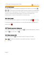
6.5.1.2 Brightness of the screen / night mode
By touching the screen brightness button 9.2
a small window opens in which you
can adjust the brightness and switch between
●
day mode:
and
●
night mode::
In the night mode the screen brightness is slowly reduced ten seconds after the last user
interaction, if no alarm condition exists. If an alarm occurs or the screen is touched, the
brightness immediately returns to 100 %.
The screen brightness button 9.2 also serves as an indicator of the current brightness level:
Caution: Adjust the brightness of the screen depending on the brightness of the
surroundings! Important information could be missed!
Page 27
6 The V-Spec™ Monitoring System (VSMS)
6.5.1.3 Switching the screen display
The V-Spec™ Monitoring System offers you two different screens:
●
the main screen described above with trend display and
●
a screen with the enlarged display of the spectra 10 .
With the touch of the button 9.3
a screen opens with the spectral data:
On this screen, you can see in the upper part the medical parameters and the respective
alarm limits. In the lower part, a magnification of the spectra 10 is shown.
The spectral view consists of the
●
pulsatile absorption spectrum:
shown as white curve, the
●
extracted blood spectrum:
shown as a red curve and the
●
tissue spectrum:
shown as a green area,
Page 28
6 The V-Spec™ Monitoring System (VSMS)
are each shown in a wavelength range of 500nm to 800nm. The button 9.3 will change in
the spectra view
and serves now to switch to the main screen. The display areas
"Settings“ 9 and "Status Indicators“ 7 on the right side remain otherwise unchanged.
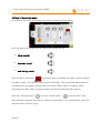
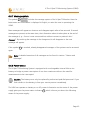
6.5.1.4 Main menu
By touching the menu button 9.4
the main menu opens:
The main menu contains the following sub-menus:
•
Volume menu:
•
Data-output menu:
•
POST and reset menu:
•
Information menu:
By touching the button
you can exit the menu.
Page 29
6 The V-Spec™ Monitoring System (VSMS)
Settings in the volume menu:
By touching the button the window for setting the alarm sounds opens:
With the help of the sliders you can adjust the volume for the
●
alarm sounds
●
the heart sound
●
and the key sound
With the alarm off button
authorized users can disable the audio output including
the alarm system. This option is secured with a PIN-code. The user will be made aware by
an audible tone at regular intervals that the acoustic alarm output is disabled. When
operating the VSMS with connected systems the alarm forwarding will continue.
With the "melody button"
and the “sound button”
you can select if the
optional alarm melodies (see section "alarms and messages“) or sounds shall be used. The
selected field is shown in gray.
Page 30
6 The V-Spec™ Monitoring System (VSMS)
Setting data output:
In the data-output menu you can select how the output of measurement data via the serial
RS232-interface 17 shall be done.
You have the option to choose between the
•
V-Spec™ Link protocol
and the
•
PHILIPS IntelliBridge open interface protocol
The selected field is shown in gray.
Page 31
6 The V-Spec™ Monitoring System (VSMS)
POST and reset menu:
In this submenu, you have the option to display the POST screen (s. sec. 6.6.1 Turning on
the VSM) again, or reset the settings to factory settings. Before you can actually reset the
settings to factory settings, a security query is shown:
Page 32
6 The V-Spec™ Monitoring System (VSMS)
Performing the settings reset will restore following settings to the factory default values:
•
alarm melodies,
•
volume settings,
•
display lightness,
•
night mode,
•
parameter alarm limits and
•
parameter selection of the trend graph fields
Information in the information menu:
Via the Information menu additional information to VSMS will be made available to you:
The top row displays the serial number of the VSM and the firmware version of the
multifunctional board. The second field shows the version number of the VSM monitoring
software. The third and largest field shows the serial number of the connected V-Spec ™
sensor, the enabled measurement parameters, the remaining operating time, and the
version numbers of the sensor firmware and of the sensor driver.
Below you will find the Senspec contact address.
Page 33
6 The V-Spec™ Monitoring System (VSMS)
6.5.1.5 Language setting
By touching the button 9.5 in the upper left corner of the screen you can choose between
the languages German and English. The currently selected language is shown in the upper
left corner of the screen:
English:
German:
6.5.1.6 Setting Date and Time
Open the sub-menu date / time by touching the symbol 7.5
.
The menu for setting the date and time will open up:
The date and time can be set by pressing the correspondent + or - buttons.
Confirm the entry with the "confirm" box
, which closes the menu.
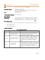
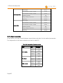
6.5.1.7 Storage of the user settings
Table 1 gives the default settings, and what settings made by the user are stored at a
restart and which will be reset to the default values.
Page 34
6 The V-Spec™ Monitoring System (VSMS)
Table 1: Settings-Management
Setting
Default values
Setting
SpO2 Limits
85%, 100%
SpO2 Limits
PR Limits
40 bpm, 150bpm
PR Limits
StiO2 limits
60%, 95%
StiO2 limits
Alarm system status
ON
Alarm system status
Alarm volume
75%
Alarm volume
Pulse tone volume
0%
Pulse tone volume
System-click-volume
25%
System-click-volume
Melodies
OFF
Melodies
Dimmer
100%
Dimmer
Night mode
OFF (DAY)
Night mode
Time
GMT + 1h
Time
Audio-OFF-Time
30 seconds
Audio-OFF-Time
Trend views
1. SpO2, ( time frame: 10min)
2. StiO2, ( time frame: 10min)
3. Pleth ( time frame: 12sec)
Trend views
Page 35
6 The V-Spec™ Monitoring System (VSMS)
6.6 The Monitoring with the V-Spec™ Monitoring System
Connect the sensor to the V-Spec™ Monitor as described in section "Connecting a VSpec™ Sensor“. Check the sensor status by means of the sensor status indicator on the
screen of the turned on VSM 7.4 .
Note: The operating life of the V-Spec™ Sensors is limited. Please refer to the
instruction manual of the sensor for more information!
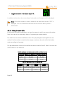
6.6.1 Turning on the VSM
Turn on the VSM by pressing the power switch 14 n the back of the VSM. After turning on
the VSM the Senspec-Logo appears. When you turn on the VSM it performs a self-test
("Power-on self-test (POST)"). The result is displayed to you on the so-called POST-screen
shown below:
Page 36
6 The V-Spec™ Monitoring System (VSMS)
On the POST screen serial number, software releases, existing interfaces, tested functions
and the respective status will be displayed:
●
Green check mark:
Test was successful,
●
Red check mark:
could not be verified or there is a problem.
In addition to the tests that the system can automatically perform, further states are to be
checked. These tests relate to the audio system and the display and are to be performed by
the user. They are marked with a question mark
. Upon starting the VSM gives an
audible signal. If no signal tone is audible and/or the display is not lit or not readable, the
VSMS is not functional and must not be put into operation.
If the "Power-on self-test" failed, the message "Power-on self-test not passed! (Error xxx)"
appears where xxx represents an error code. In this case, the VSMS cannot be put into
operation. If the test was successful, the message "Power-on self-test passed!" appears,
the post-screen is automatically closed and the V-Spec™ Monitor is ready for operation.
Caution: If problems occur, immediately contact the responsible service personnel!
6.6.2 Medical measurement parameters
The display area "medical parameter“ 2 shows you the medical variables. These are the:
●
Oxygen saturation of the arterial blood SPO2 in %:
●
Pulse rate PR in bpm:
Page 37
6 The V-Spec™ Monitoring System (VSMS)
●
Oxygen saturation of the tissue StiO2 in %:
In addition to the values the current alarm limits and unit of measure will be displayed.
Note: If the alarm system is muted, instead of the alarm limit the text "OFF" is
displayed. This is an additional reference that the acoustic alarm system is
deactivated.
6.6.2.1 Setting the alarm- limit
By touching the medical parameters, an input box opens in which you can set the alarm
limits. You can do this either by a slider, or by entering a numerical value.
The slider bar has areas with different colors. Thus physiological meaningful limits are
marked. If a limit value is set within the orange or red zone the color of the limit value
varies according to the range.
The adjustable alarm limits and the default values are listed in Table 2. Table 3 contains the
colored areas on the slider bar.
Table 2: maximum and minimum alarm limits and default values
Parameter [Minimum; Maximum] Default Values
SPO2 [%]
[60;100]
[85;100]
PR [bpm]
[30;240]
[50;140]
StiO2 [%]
[0;100]
[60;95]
Table 3: Physiological mark on the slider bar
Parameter
Page 38
Red
Yellow
Green
SPO2 [%]
60-79
80-84
85-100
PR [bpm]
30-40; 200-240
40-50; 140-200
50-140
StiO2 [%]
0-35
35-45
45-100
6 The V-Spec™ Monitoring System (VSMS)
Adjusting with the help of the slider:
Press the Slider of the upper or lower limit and shift it on the desired value. The field
of the selected limit will be grayed and the value will be updated immediately:
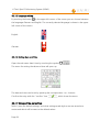
Adjusting by means of the numeric keys:
Press the limit value you want to change (1). Delete the current positions with the
delete key (2). Enter the desired value (e.g. “90“: 3+4) and confirm the input with
the small confirmation field (5). The new limit is displayed updated. If an invalid
value is entered (e.g. upper limit less than lower limit or limit outside of the
adjustable range), the value will be adjusted automatically. Confirm the set limit
values, by pressing the confirm button (6).
Page 39
6 The V-Spec™ Monitoring System (VSMS)
Note: Please note that not all set alarm limits are stored in a system reboot. Detailed
information can be found in the section 6.5.1.7 Storage of the user settings.
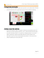
6.6.3 Display area trend graphs
Note: Align the screen display so that you, as a user, in respecting the responsibility
for the patient, have the best overview of the required values for your application.
6.6.3.1 Trend graphs
The V-Spec™ Monitor has a display area for the trend graphs 3 , which you can
customize. It consists of the field 3.1 , 3.2 and 3.3 . The trend graphs are displayed with the
same color as the corresponding parameters. You can assign each field one of the medical
and technical parameters, by dragging the symbols 2.1 , 2.2 , 2.3 , 6.1 or 6.2 to the desired
Page 40
6 The V-Spec™ Monitoring System (VSMS)
field 3.1 , 3.2 or 3.3 :
A parameter can also be used in several fields parallel.
Below the edges of the trend graphs the time span of the trend graph can be seen,
whereby the current time is shown on the right. You can change the time span by pressing
on the field and wipe to the right or left:
The time span is set for all trend graphs and can be adjusted between a minimum of 10
minutes and a maximum of 72 hours. The value range of trend graphs is automatically
scaled for the medical parameters, according to the values displayed in the selected time
range. Maximum and minimum of the display are visible as numeric values right next to the
field. The current alarm limits are shown as red horizontal lines. The area outside of the
alarm limits is highlighted in red.
Page 41
6 The V-Spec™ Monitoring System (VSMS)
6.6.3.2 Plethysmogram
The plethysmogram can be displayed by dragging the heart symbol on one of fields 3.1 ,
3.2
or 3.3 . The time span of the plethysmogram can be set equivalent to the trend graphs,
and can be set to a value between 15 and 75 seconds in 15-second increments. The set
time span is visible below the plethysmogram. The scaling of the height of the
plethysmogram is carried out automatically for the selected range.
6.6.4 Heart symbol
The active pulse (pulse cycle) is apparent in the vibrant heart symbol 4
. f no sensor
is connected or applied or the pulse rate is too low, the heart-symbol is displayed with a
question mark
.
6.6.5 Technical parameter display area
In the lower screen area you see the display area 6 for the technical parameter "Pulsation
Index" PI 6.1 and „Pleth Index“ PLI 6.1 .
6.6.6 Alarm Indicator field
The alarm indicator field 7.1 shows the alarm status in the event of an alarm.
Note: The alarms are explained in more detail in the section "Alarms and
Messages”.
Page 42
6 The V-Spec™ Monitoring System (VSMS)
6.6.7 Message system
The symbol 7.2
includes the message system of the V-Spec™ Monitor. Here the
latest news and information is displayed in English, to assist the user in operating the
VSMS.
New messages will appear as a banner and disappear again after a few seconds. If several
messages are present at the same time, the information about it takes place at the end of
the message (e. g.: Sensor is now connected but without contact to patient's skin!
(1more)”). By touching the message in the foreground it will disappear or the next
message will appear.
If the symbol 7.2 is touched, already disappeared messages of the systems can be accessed
again.
Note: A detailed overview of all messages can be found in section "Alarms and
Messages"
6.6.8 Power status
The V-Spec™ Monitoring System is equipped with a rechargeable internal lithium ion
battery to bridge a power interruption of one hour maximum without the need for
measurements to be interrupted.
Caution: The battery must only be replaced by authorized qualified personnel. If you
find a defect in the battery, inform your service partner immediately.
The VSM can operate on battery or on AC power. Information on the status of the power
supply gives you the power status indicator 7.3 , which informs you about the following
states of the power supply:
Page 43
6 The V-Spec™ Monitoring System (VSMS)
Power mode active, battery fully charged:
●
The VSM is connected to the external power supply and the battery is fully charged.
Power mode active, battery fully charged:
●
The VSM is connected to the external power supply and the battery is charged.
Battery mode active, Battery fully charged:
●
The battery is fully charged and enables the operation for approx. 1h
Battery mode active, battery charge low:
●
The battery charge level decreases. The operation is possible for max. 15 min. A
medium priority alarm informs you about it.
battery operation active, battery load critical:
●
The battery load does not suffice for the operation of the VSMS. The system shuts
off four minutes after the appearance of the symbol and the alarm "Critical Battery
charge" if no power cord is connected.
A re-charging is carried out automatically when connected to the electrical network. If the
battery is fully discharged, approximately four hours are required to fully charge the
battery.
Page 44
6 The V-Spec™ Monitoring System (VSMS)
6.6.9 Sensor status
The status indicator of the sensor 7.4 nforms you about the current status of the sensor.
This is supported by the message system. The indicator shows you the following states of
the sensor:
Sensor not connected:
●
There is no sensor connected to the VSM
Sensor not applied:
●
The sensor is connected to the VSM, but has no skin contact to the patient.
Sensor active:
●
The sensor is connected to the VSM, applied on the patient and is working properly.
Following the stabilization of the readings, you can see it on the screen.
Sensor temperature is too high:
●
The sensor is connected to the VSM, applied on the patient and the sensor
temperature is too high. The sensor turns off, a high priority alarm is generated and
the text message "High sensor temperature - remove or change sensor!" appears.
Warning: Remove a sensor with a too high temperature immediately from the
patient and from the VSM! The alarm is only ended by removing the sensor from
the VSM.
Caution: If a too high temperature is displayed at a sensor frequently, the sensor
must not be used again! In this case, use a different V-Spec™ Sensor and contact
your Senspec partner!
Page 45
6 The V-Spec™ Monitoring System (VSMS)
Sensor operating time has expired:
●
The sensor is connected to the VSM and the operating time of the sensor has
expired. The sensor turns off (please note below!), a medium priority alarm will be
generated and the text message "Sensor operation period exceeded!" will be
displayed.
Note: If the remaining operating time is under 60 minutes, the yellow, flashing text
message "connected sensor's lifetime expires in 'xx' minutes! Please change the
sensor!" is displayed on the spectra display area 10 ('xx' s the number of minutes
remaining).
If the sensor is applied while the operating time expires, it will remain in operation
and is only disabled if it is disconnected more than 15 minutes from the skin or from
the VSM. In this case, the red, flashing text message "connected sensor's lifetime
has expired! Please change the sensor!" will be displayed on the display area of
spectra 10 . A measurement operation can thus be maintained even with expired
sensor.
Page 46
6 The V-Spec™ Monitoring System (VSMS)
6.6.10 Operation with the V-Spec™ Sensor
6.6.10.1 The measurements
If the sensor is properly connected to the patient and to the VSM after a short stabilization
period the current readings of the patient will appear.
Caution: Make sure that the sensor does not move at the application site. Motion
artifacts can distort the measurement. Note the course of the plethysmogram to
identify motion artifacts.
Note: If the readings do not stabilize themselves, test the correct fit of the V-Spec™
Sensors. Make sure that the sensor cable is fixed to ensure a good strain relief.
Falling below the SPO2 value triggers a high priority alarm. Be sure to verify the patient's
status. A strong decrease of the SPO2 value produces sometimes a life-threatening
condition of the patient.
Falling below the StiO2 value produces an alarm of medium priority. Be sure to check the
status of the patient, look for any limitations in circulation. Check if, an extreme change in
the physiology of the patient or in the circulation at the monitoring point has occurred (e.
g. by the inflated cuff of a sphygmomanometer, a bruise, arterial blood sampling at the
hand at which the sensor is located, heavy hypotension, peripheral constriction of blood
vessels in response to hypothermia, drugs administered or Raynaud's syndrome).
It is possible that pulse oximeter at extremely low perfusion may only measure the
peripheral saturation, which may differ significantly from the central arterial saturation. This
"localized hypoxemia" may be a consequence of the metabolic demands of other tissues,
extract the oxygen proximal to the monitoring location under conditions sustainable of
peripheral hypo perfusion. (This can also occur in the case of a pulse rate, which correlates
with the ECG heart rate.)
Page 47
6 The V-Spec™ Monitoring System (VSMS)
Caution: If frequently a weak blood circulation is displayed, a better perfusion
application site must be sought. Until that is done, the oxygenation status of the
patient must be checked in a different way.
Corrective Action:
f the SPO2 display values show significant differences the following should be done:
●
Ensure that the sensor is applied correctly and safely on the patient
●
Select a application site with the best possible circulation
●
Rub the measuring site with 70% isopropyl alcohol pad or rubefacient cream (1030% methyl salicylate and 2-10% menthol) for 20-30 seconds in order to improve
the blood circulation. Strong vasodilatory creams, such as like nitroglycerin
ointment, are not recommended.
●
If possible, remove electro-surgical or other devices that may cause electrical
interference
●
If possible place the sensor at a location with low ambient light. The VSM with
integrated V-Spec™ Technology is sufficiently protected against ambient light, but
excessive ambient light can cause measurement errors.
Caution: If there are doubts as to the accuracy of measurements, the vital signs of
the patient should be checked in any other way before the functionality of the VSM
will be further investigated.
Page 48
7 Alarms and Messages
7 ALARMS AND MESSAGES
7.1 Introduction
In the following section the VSMS alarm system as well as the messages displayed on the
display will be explained in more detail.
The alarm system is an important element in the VSMS. The operator should be familiar
with the following information before the system is put into service.
The V-Spec™ Monitoring System allows the acoustic and visual output of alarm conditions.
The acoustic alarm messages will be issued over the built-in speaker of the V-Spec™
Monitor. The visual output is carried out through various displays on the screen of the
monitor. A distinction is essentially be made between the visual alarm indicators and the
reporting system. The audible alarms can be muted for a period of a half minute, one
minute, or two minutes, the visual alarm output can not be disabled.
Warning: Always adjust the volume of the alarm system to the ambient noise!
Alarm conditions may not be observed or noticed too late if you do not follow this
instruction.
Page 49
7 Alarms and Messages
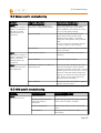
7.2 Alarms
The alarms of the VSM are distinguished in "high", "medium" and "low". The alarms will
be further divided into medical and technical alarms. The table 4 contains a general
overview of the possible alarms.
Table 4: VSMS overview of the alarms
Alarm
Description
•
High
priority
•
•
•
Medium
priority
Low
priority4
•
Audible and visual alarms for exceeding the SPO2 -limits (medical,
with optional melody)
Audible and visual alarms for a critical battery level (technical, only
as melody alarm ) and a too high sensor temperature (technical, no
melody)
Immediate
response required
Audible and visual alarms for exceeding the alarm limits of the
parameter pulse rate, and StiO2 (medical, with optional melody)
Audible and visual alarms for problems with the monitor (POST
failed), the sensor (operating time has expired, not calibrated, not
Immediate
connected, without skin contact), the battery (defective, low battery response required
condition (only melody alarm )), at connection problems with the
multi-functional board or a defective V-Spec™ extension cable
(technical, without a melody)
Acoustic and visual alarms at low signal quality, exceeded
Attention and
parameter update period or an identified problem with the monitor
response required
(technically, without a melody)
7.2.1 Acoustic Alarm Indicators
The acoustic alarm tones (without melody) are marked as follows:
High priority:
Sequence of ten high sounds, sounding in four bursts (3,2,3,2),
repeating every 10 seconds
Medium priority:
Sequence of three medium pitch tones, sounding as a single burst,
repeating every 10 seconds
Low priority:
Sequence of two low pitch tones, sounding as a single burst,
repeating every 30 seconds
Audible alarm signals can be muted with the help of the alarm pause button
30 seconds, one minute or two minutes (push > 3 seconds).
Page 50
9.1
for
7 Alarms and Messages
Note: The permanent muting of the alarm system is permitted only to authorized
users and only available with a PIN-code. As a reminder, that the alarm system is
inactive, you will hear a "reminder signal" every ten minutes.
Note: For more information on the alarms and the alarm melodies that can be
optionally set parameters specific can be found in section 9.7.2 Alarm melodies
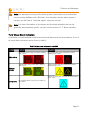
7.2.2 Visual Alarm Indicators
A distinction is made between medical and technical alarms with the visual alarms. A list of
all visual alarm indicators can be found in table 5 .
Table 5: Visual alarm indicators in the VSMS
Alarm
Medical
Technical
Red frame around the SPO2 value, flashing
with f=2Hz
Red symbol with three exclamation marks,
flashing with f=2Hz
Yellow frame around the value, flashing
with f=1Hz
Yellow symbol with two exclamation marks,
flashing with f=1Hz
High priority
Medium
priority
Symbol in Cyan cyan icon with an exclamation
mark, static
Low priority
No medical alarm low priority included in
the VSMS
Page 51
7 Alarms and Messages
7.2.3 Alarm Limits
The adjustable alarm limits are listed in table 6.
Table 6: maximum and minimum alarm limits and default values
Alarm
[Minimum;Maximum] Default Values
SPO2 [%]
[60;100]
[85;100]
PR [bpm]
[30;240]
[50;140]
StiO2 [%]
[0;100]
[60;95]
Note: The alarm limits of the SPO2 parameter are set back to the default values
[85;100] each time the monitor is re-booted.
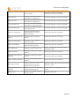
7.2.4 Alarm messages
In addition to the audible and visual alarms the VSMS issues more information and
descriptions of the alarm as a text message in the English language via the message system
VSMS (see section 6.6.7 Message system). You can find an overview of all alarms and the
associated messages in table 7. Z In addition, the table contains information, whether an
alarm melody is available optionally ("opt.").
In addition to the alarm messages also information are issued which signal no alarm. Like
the alarm messages the info messages contain important information and must not be
ignored. The information messages are shown in table 8 .
Page 52
7 Alarms and Messages
Table 7: Alarms in the VSMS and associated messages
Priority Type Alarm description
Melody
Message (English & German)
low SPO2 saturation
opt: SPO2
SpO2 low limit violation!
SPO2 unterschreitet den Alarm-Grenzwert!
high SPO2 saturation
opt: SPO2
SpO2 high limit violation!
überschreitet den Alarm-Grenzwert!
Critical battery load
Critical battery charge – connect main supply
fix: battery- or VSM will shut down!
critical
Batterie kritisch - Netzstecker anschließen
oder Abschaltung erfolgt!
Med.
High
priority
Tech.
Sensor temperature too high
---
Low pulse rate
opt.: PR
PR low limit violation!
PR unterschreitet den Alarm-Grenzwert!
High pulse rate
opt.: PR
PR high limit violation!
PR überschreitet den Alarm-Grenzwert!
low SPO2 saturation
opt.: StiO2
StiO2 low limit violation!
StiO2 unterschreitet den Alarm-Grenzwert!
High StiO2 saturation
opt.: StiO2
StiO2 high limit violation!
StiO2 überschreitet den Alarm-Grenzwert!
Med.
Medium
priority
Tech.
High sensor temperature – remove or change
sensor!
Überhöhte Sensortemperatur - Sensor
entfernen oder ersetzen!
Power-on self-test failed
---
Power-on self-test failed with error xx!
Power-On-Self-Test fehlgeschlagen!
Fehlercode: xx
Sensor operating time has
expired
---
The sensor operation period is exceeded!
Sensor hat seine Lebens-/Betriebsdauer
überschritten!
Sensor not calibrated
---
The connected sensor is uncalibrated!
Der angeschlossene Sensor ist nicht kalibriert!
Sensor not connected
---
Lost connection to the sensor!
Verbindung zum Sensor verloren!
Sensor not installed
---
Sensor lost skin contact!
Sensor hat den Hautontakt verloren!
Low battery load
Fest:
Low battery charge!
battery_low Der Betterieladezustand ist niedrig!
Defective battery
---
Battery defective!
Die Batterie ist defekt!
Multi functional board not
attainable
---
No connection to multifunction board!
Keine Verbindung zum Multifunktionsboard!
Page 53
7 Alarms and Messages
Weak signal quality
Low
priority
Parameter update time
Tech. exceeded for more than 30s
Monitor error
---
Low signal quality!
Die Signalqualität ist gering!
---
Data update period exceeded 30 seconds!
Der letzte gemessene SpO2-Wert ist älter als
30 Sekunden!
---
Monitor fault xx!
Kritischer Monitor-Fehler %i!
Table 8: Information messages
Messages
Power-on self-test passed! VSM is ready for use!
Power-on self-test failed with error xx!
Sensor is now connected but without contact to patient's skin!
Low pulsation index! Please check sensor application!
Main supply disconnected!
Main supply is not connected!
Main supply connected!
Monitor problem xx!
7.2.5 Required Responses
The required responses to the alarms are provided in table 9.
Table 9: Alarms and required response
Alarm description
Required Response
SPO2 saturation low
Immediately, check patient status,
Death or irreversible damages
terminate any hypoxia
SPO2 saturation high
Immediately, check patient status,
Irreversible damages, reversible damages
terminate any hypoxia
Critical battery load
Immediately, connect the power
cord
VSM shuts down, monitoring can not be
continued
Sensor temperature too
high
Immediately, remove sensor and,
if required, replace by other V-
Pain and reversible damages to the
measuring point by burning, sensor
Page 54
Consequences, if response is lacking
7 Alarms and Messages
Spec™ Sensor
terminates measuring operation,
monitoring can not be continued
Low pulse rate
Promptly, check patient status,
terminate any bradycardia
Irreversible damages, reversible damages
High pulse rate
Promptly, check patient status,
terminate any bradycardia
Irreversible damages, reversible damages
SPO2 saturation low
Promptly, check patient status,
terminate any hypoxia/ischemia
Irreversible damages, reversible damages
SPO2 saturation high
Promptly, check patient status,
terminate hypoxia
Irreversible damages, reversible damages
Sensor not calibrated
Promptly, replace V-Spec™
Sensor and send it to your
Senspec partner
Monitoring cannot be continued
Sensor operating time has
expired
Promptly, replace V-Spec™
Sensor
Monitoring cannot be continued
Sensor not connected
Promptly, connect V-Spec™
Sensor with VSM
Monitoring cannot be continued
Sensor not installed
Promptly, install V-Spec™ Sensor
again at measuring point
Monitoring cannot be continued
low battery load
Promptly, connect power cord
Battery is discharged, monitoring can be
continued limited
Defective battery
Promptly, contact your Senspec
partner
Monitoring cannot be continued
Multi function board not
attainable
Promptly, contact your Senspec
partner
Monitoring cannot be continued
Sensor extension defective
Promptly, contact your Senspec
partner
Monitoring cannot be continued
Weak signal quality
Timely, check Sensor application,
change measuring point or
stimulate blood circulation
Measured values may not match the actual
parameter values
Parameter update time
exceeded
Timely, check Sensor application,
change measuring point
Measurement of the parameter is not
possible
Monitor error
Timely, turn off VSM, contact
Senspec partner
Damage to the VSM
Page 55
7 Alarms and Messages
7.3 Alarm-System-Reset
If the V-Spec™ Monitor is switched off, certain settings are reset to default value if they
have been changed by the operator. This is also the case if the system is restarted after a
"Critical battery load" alarm. A list of the default settings and if the standard values or user
inputs are added after a reboot can be found in table 1 in chapter Fehler: Referenz nicht
gefunden Fehler: Referenz nicht gefunden on page 35. If an error occurs when you save
the user settings, it may happen that all settings will be set back to the default values.
7.4 Alarms in the past
The VSMS stores alarms that have occurred. This gives the user information about alarm
states that lie in the past and are otherwise not directly visible.
In the case of medical alarms a past alarm is indicated by a slow flashing alarm icon next to
the corresponding parameters. Past technical alarms will be signaled by a slow flashing
alarm symbol in the alarm indicator field (see section 6.6.6 Alarm Indicator field). By
tapping on this alarm symbol the corresponding alarm message will appear. In addition to
the text of the alarm message also the time of the first occurrence of the alarm is
displayed. By tapping on the message it will disappear.
7.5 Alarm triggering
From the occurrence of an event on the patient (e.g. hypoxia) to the triggering of the alarm
system-related delays occur. The parameters are subject to different notification procedures
that cause this delay. The "parameter update period" is 1Hz in the VSMS. The time that
elapses until the update of the displayed parameters, i.e. the time between two valid
values is therefore one second.
Figure 1 illustrated the delay that occurs from the entry of an event until triggering the
alarm with an exemplary SPO2-course. The alarm condition occurs at time t1 and is detected
at time t2 by the algorithm. At time t3 the alarm is issued. The time period t2-t1 is
Page 56
7 Alarms and Messages
determined by the averaging and processing times of the algorithms and is called " alarm
condition delay". The time period t3-t2 is the delay occurring by the signal run time within
the VSMS or by the alarm forwarding to the connected systems and is called " alarm signal
generation delay".
Figure 1: Illustration of the alarrm delay at the instance of parameter S PO2
If the VSMS is used as standalone system, the time t3-t2 is significantly less than one
second, which is below the „parameter update period“. Since the time t3-t2 to the time
t2-t1 is negligible, the overall delay is mainly characterized by the time t2-t1.
The delay times of the medical alarms are given in table 10.
Table 10: Delay times of the alarm system
Alarm
Delay t2-t1
SPO2
15 seconds
PR
5 seconds
StiO2
15 seconds
Technical alarm
<1 seconds
Page 57
7 Alarms and Messages
The delay time from determining the alarm condition ( t2) until the output over the serial
port, is a maximum of two seconds.
Note: If the VSMS is used in connection with other systems, the delay times of the
designated manufacturer are valid for the connected system.
Note: While a parameter is invalid or is stabilized, the alarm-monitoring of this
parameter is inactive. Detailed information can be found in the section 9.2.2 .
7.6 Alarm Log
The VSM records internally the alarms in log files. At each start of the VSM a new file is
created. This is permanently stored even in the case of the loss of the operating voltage. In
a log file for each alarm event (start, end, limit changes ...) an entry is created, which is
named with the respective alarm ID. As entries of the events are included:
•
Time,
•
Alarm event type (Start (START), end (END), limit change (LIM), Alarm system status
(ASS)) (LIM and ASS only if there is an alarm),
•
Alarm priority,
•
Alarm description,
•
set alarm limits,
•
The current parameter value
•
Alarm volume and
•
Alarm system status.
Note: The alarm log file is saved internally and can be read only by authorized
personnel.
Page 58
8 Data Communication
8 DATA COMMUNICATION
8.1 Overview
During the V-Spec™ monitoring, current patient data can be issued via the serial interface
17
(RS-232), which is located on the side panel of the VSM. This port can be connected
with external instruments such as multiparameter monitors, personal computer (PC) and
Poly (SOMNO) graphs. When connecting the VSM to an external device, verify correct
operation prior to clinical use. Both the VSM and the external device must be connected to
an earthed wall socket. The respective communication protocol must be set up as
described in this section.
Each PC or non-medical instrument, which is connected to the serial VSM data interface,
must be certified according to the IEC 60950-Standard. All combinations of equipment
must correspond to the requirements of the IEC standard 60601-1. Anyone who connects
an external device with the VSM configures a medical system and is therefore responsible
to ensure that the system corresponds with the requests of the standard to IEC 60601-1-1
and the electromagnetic compatibility standard IEC 60601-1-2.
Warning: If you connect devices with the V-Spec™ Monitor via the serial interface,
be sure to use the RS232 isolator (ref: “RS232-IS”)!
Page 59
8 Data Communication
8.2 Data protocol
8.2.1 Serial data interface
The serial interface 17 of the V-Spec™ Monitor is used to enable a serial data
communication between the V-Spec™ Monitor and other devices. The interface is located
on the right-hand side of the VSM:
The layout of the interface connector is visible in the following figure:
Table 11 specifies the Pin arrangement:
Table 11: RS232 pin assignment
Pin
1
Reserve
2
Transmit Data (Tx)
3
Receive Data (Rx)
4
Reserve
5
Signal ground
6-9
Page 60
Explanation
Reserve
8 Data Communication
8.3 V-Spec™ Link communication protocol
The V-Spec™ Link communication protocol is a proprietary uni-directional protocol, to
enable the exchange of real-time patient data between the V-Spec™ Monitor and other
devices.
8.3.1 Interface settings
For establishing a communication the parameters at the receiver must be set according to
table 12 :
Table 12: RS232-Interface settings
Parameter
Setting
Standard
RS-232
Baud rate
9600
Data bits
8
Stop bits
1
Parity
None
Flow Control
None
8.3.2 V-Spec™ Link data transfer
The V-Spec™ Link communication protocol issues one data row per second. The header
will be issued every 50 seconds, or in case of a change of information contained in the
header (e.g. alarm limits).
The output of the parameters is carried out delayed via the serial interface to the output on
the screen. The delay is a maximum of two seconds. Not included here is the time for the
processing and output to the connected device.
8.3.3 Layout of the header and the data arrays
The data output takes place in ASCII-format, whereby the fields are separated by tabs. The
structure of the header and the data arrays is specified in table 13:
Page 61
8 Data Communication
Table 13: Assembly V-Spec™ Link protocol
a)
Monitor
Line 1
Header Info Line 2
Monitor-SN: <Value> Serial number of VSM
Software: <Value> version number of the VSM
Monitoring Software
Sensor
Line 1
Header Info Line 2
SN: <Value> Serial Number
SW: <Value> version number of the sensor software
Data arrays
Header
Line 1
Line 2
Line 3
Line 4
Line 5
Line 6
Line 7
Date&Time: [yyyy-mm-dd hh:mm:ss]
SPO2 [%] <low limit>:<high limit>
PR [bpm] <low limit>:<high limit>
StiO2 [%] <low limit>:<high limit>
PI [%]
PLI [%]
Status
Data arrays
Line 1
Line 2
Line 3
Line 4
Line 5
Line 6
Line 7
<date><time>
<SPO2 value><Limit violation>a) <unstable>b)
<PR value><Limit violation>a) <unstable>b)
< StiO2 value><Limit violation>a) <unstable>b)
<PI value>
<PLI value>
<code>c)
A plus sign („+“) behind a reading indicates the set value is above the upper alarm limit.
A minus sign ("-") Indicates that the lower limit was exceeded.
b)
A "u" behind a reading indicates that the returned value is marked as not stable.
c)
The status codes contain further information of the VSMS. You can find a detailed list of
all status codes under 8.3.4 Status Code.
Depending on the sensor status, the quality of the measured values will be given out as
follows:
Table 14: Forms of output of the parameters
Sensor position, quality of the readings
On Patient, parameter is valid
On Patient, parameter not stable
On Patient, parameter is invalid
Not on patient
Sensor not connected
Page 62
Parameters
Value
Value u
i
---/-
8 Data Communication
8.3.4 Status Code
The specified status codes in table 15 are put out through the serial interface:
Table 15: Status Codes
Meaning
Status
Codes
Critical battery load
BC
Sensor temperature too high
HT
Incompatible sensor
SI
Sensor defective
SD
Sensor operating time has expired
SE
Sensor not calibrated
SNC
Sensor not connected
NoS
Sensor not installed
SO
Low battery load
BL
Defective battery
BD
Multifunctional board not attainable
nMFB
Sensor extension defective
ECD
Weak signal quality
LSQ
Parameter update time exceeded
UPE
Alarm system OFF
AO
Alarm system paused
AP
Power-on self-test failed
PF
Monitor problem xx
Pxx
Page 63
9 Technical description
9 TECHNICAL DESCRIPTION
The VSMS is a medical device according to EC Directive 93/42/EEC, certified according to
the International Standards IEC 60601-1, DIN EN 80601-2-61 and EN ISO 10993-1.*
* further relevant standards which were taken into account in the device production can be inquired at
Senspec GmbH.
9.1 Environment, Transport and Storage Conditions
9.1.1 Transport / Storage Conditions
The following conditions apply to all units of the V-Spec™ Monitoring System (transport/
storage in original packaging)
Temperature:
0 - 50 °C (32 – 122°F)
Humidity:
10 – 93% (non-condensing)
For the listed devices, we recommend the following long-term storage conditions:
Temperature:
15 – 26 °C (59 - 78°F)
V-Spec™ Soft Sensor, V-Spec™ Sensor, Attachment Tape
Humidity:
40 – 60 %
Attachment Tape AT-VS
9.1.2 Operating Conditions
Temperature:
10 – 40 °C (50 – 104°F)
Humidity:
15 – 93% (non-condensing)
9.2 V-Spec™ Monitor (VSM)
9.2.1 Physical Characteristics
Weight:
Page 64
2.9 kg (6.4 lbs)
9 Technical description
Size:
23,4 cm x 28.0 cm x 12.0 cm (HxWxD)
Placement / fixation:
standing, on rubber feet
VESA-Mount MIS-E (200mmx100mm, M4) for fixation at
systems with VESA Standard
Kennsington Lock
Lock:
Casing ingress protection: IPX1-splashproof
9.2.2 Display
Display type:
9“ (23cm) colour display (800x480 pixel (WVGA) TFT), LED
backlight, brightness
400cd/m², contrast ratio 600:1,
large angel of vision (88° every direction at contrast >10:1).
Data update period:
•
numerical values of SPO2, PR, StiO2 and all other physiological measuring values: 1s
•
Pleth diagram: 40Hz
•
Online trend graphs: 1s
Validity of parameter:
Table 16: Validity of parameter
Quality
Attributes
Valid
Parameters displayed in
pre-defined colours
Instable
Parameters displayed in
gray or darker colour
Invalid
‘- -’ replaces the
parameter value
Description
The respective data are valid. The activated
trend graphs are being updated. The alarm
system for the parameter is active.
The respective data are not stable and probably
do not reflect the patient's data. When one
parameter is marked as instable, the activated
trend graphs are being updated. The alarm
monitoring for the respective parameter is
active.
The respective data are instable and do not
reflect the patient’s data. When one parameter
is marked as invalid, an "empty value" (NaN) is
entered into the trend graph. The alarm
monitoring for the respective parameter is not
active.
Page 65
9 Technical description
Trend graphs:
•
displayed parameters freely selectable
•
time domain (x-axis) for online trends can be set between 10 min and 72 h
•
values margin (y-axis) is scaled automatically depending on the value within the
displayed time domain.
Plethysmogram:
•
time domain (x-axis) selectable between 15, 30, 45, 60 and 75 seconds
•
values margin (y-axis) is scaled automatically depending on the value within the
displayed time domain
Display options:
•
brightness can be adjusted during the monitoring
•
switchable between day mode (continuous brightness) and night mode (brightness
is automatically reduced, if no interaction is made (input, alarm))
The user is offered two selectable measurement displays:
Standard screen:
•
updated medical and technical measuring values, alarm limits, online trends and/or
plethysmogram and heart symbol
•
minimized display of spectral data
•
status messages
•
status indicators for battery, sensor, alarm and wall clock time.
•
settings of volume, display brightness, serial output protocol
Page 66
9 Technical description
Spectral screen:
•
updated medical measuring values, alarm limits
•
spectral data instead of trend graphs, technical parameters and heart symbol
•
status messages
•
status indicators for battery, sensor, alarm and wall clock time.
•
settings of volume, display brightness, serial output protocol
9.2.3 Connections
•
serial conetion RS-/EIA-232
•
available protocols: - Philips IntelliBridge Open Interface
- V-Spec™ Link
Note: The VSM does not provide the nurse call option.
9.2.4 Electrical characteristics
Internal battery:
rechargeable, sealed lithium-ion battery
Duration:
1.0 h (at 100 charging condition, new battery, 20°C)
Charging time:
4 h from 0% to100% charging condition
Power receptacle:
IEC 60320-C14 device connection
Mains voltage:
100 - 240V~ (50/60Hz)
Fuses:
2x 2A device fuses, time-lag fuse, 5 x 20mm
Power input:
max. 2 Ampere
Operating mode:
designed for continuous operation
Page 67
9 Technical description
Caution: The internal battery must be replaced by authorized staff only.
Caution: Chapter 11.2.1 Fuse change describes how to replace the fuses. Use only
fuses with the specifications given in this manual. If you use other, not permitted
fuses, any guarantee claim expires.
Electrical safety:
Type of protection against electric shock:
Class I (if mains operated)
Class II (with internal voltage supply)
Degree of protection against electric shock:
Type BF, APPLIED PART –
DEFIBRILLATION checked
Degree of protection against hazardous ingress of water:
IPX1-splashproof
Level of safety in the presence of a combustible mixture of anaesthetics and air, oxygen or
nitrous oxide:
not suitable for this environment
9.2.5 Voltage supply
9.2.5.1 Mains operation
If the VSM is connected to the mains supply, the power status indicator shows the
following conditions:
Mains operation active, battery fully charged:
•
The VSM is connected to the external power supply and the battery is fully charged.
Mains operation active, battery is charging:
•
The VSM is connected to the external power supply and the battery is charging.
Page 68
9 Technical description
Note: If the mains operation is not displayed, while the VSM is connected to the
mains, check the power cord, the socket, and the fuses.
Note: The VSM adjusts automatically to the respective local voltage (100-240V ~
(50/60Hz))
Note: Whenever the VSM is connected to the mains, the internal battery is
charging. Therefore we recommend keeping the VSM connected to the mains even
if it is not used. This ensures that the battery is fully charged when needed.
9.2.5.2 Battery mode
The V-Spec™ Monitoring System is equipped with a rechargeable internal lithium-ion
battery to bridge a power supply interruption of one hour maximum to ensure
uninterrupted measurements. If you use the VSM battery mode, the power status indicator
displays the following conditions:
Battery mode active, battery fully charged:
●
The battery is fully charged and allows approximately 1h operation.
Battery mode active, battery low:
●
The battery charge reduces. Operation is only possible for a max. of 15 min. A
medium priority alarm indicates this.
Battery mode active, battery charge critical:
●
The battery charge is not sufficient to operate the VSMS. The system switches off
four minutes after the symbol and the alarm “Critical battery charge“ were displayed.
The VSM can not be operated with a discharged battery. Therefore, connect the VSM to
the mains and charge the battery for some minutes, before you switch in the VSM. The
entire recharging takes about 4 hours, if the VSM is switched off.
Page 69
9 Technical description
Note: We recommend to check the internal battery every 24 months by authorized
Senspec service personnel and replace it, if necessary. This must only be performed by
authorized Senspec personnel. Replaced batteries must be recycled according to
locale regulations and not disposed of in domestic waste.
Note: If the VSM is frequently operated in battery mode, the maximum operation time
of the VSM in battery mode may decline. This may reduce the time interval between
signalling the „Battery Critical“ alarm and the switching off of the VSM.
9.3 V-Spec™ Sensors
The V-Spec™ Sensors are distinguished between the V-Spec™ Soft Sensor and the VSpec™ Sensor for use of the Attachment Tape. The following characteristics relate to the
V-Spec™ Sensor if not otherwise indicated.
9.3.1 V-Spec™ Soft Sensor Large
The V-Spec™ Soft Sensor is a combination of the V-Spec™ Sensor technology and the
Soft-Fingerclip technology, frequently used in many standard pulsoximeters.
The sensor consists of the sensor head which contains the optical components, a shaped
silicon finger clip and a cable with plug. The ergonomic shape of the silicon part which is
suitable for manual cleaning ensures ease of handling and cleaning. In order to attach the
sensor to the patient, slide the V-Spec™ Soft Sensor simply over the finger of the patient.
The digital V-Spec™ Sensor electronic system contains information such as calibration data
and Senspec identification code, which identify the sensor clearly as V-Spec™ Sensor. Any
sensor without valid Senspec identification code which is connected to the VSM is not
supported.
9.3.2 Physical characteristics
Sensor head:
Page 70
Description:
splashprooft, reusable,
Size:
43 mm x 16,5 mm x 24 mm (LxHxW)
Weight:
<8g
Colour:
black
9 Technical description
Sensor cable:
Description:
highly flexible, screened PU cable
Length:
100 cm
Colour:
white
Note: Additional information on the V-Spec™ Sensors can be found in the special
user guides for the sensors.
9.3.3 Sensor temperature
(not displayed)
Measuring range:
0 – 80°C
Resolution:
1 °C
Accuracy:
± 1 °C
9.3.4 Operating time
The operating time of the V-Spec™ Sensors is limited. Please refer to the user guides for
sensors for further information.
9.3.5 Patients
The system can be used for adults and children with a body weight of more than 20 kg /
44 lbs.
9.3.6 Permissible measuring points
Table 17: Permissible measuring points
Skin type
V-Spec™ Sensor (VSS) with
Attachment Tape (AT-VS)
V-Spec™ Soft Sensor (V-SS-L)
Fully developed
and intact
all
Patient
A/P
A/P
Measuring
point
Forehead
Finger
Page 71
9 Technical description
Note: We recommend a flat area with good blood circulation (centrally located spots
preferred). Avoid placing the sensor on top of large, superficial venues or areas with
skin damages or oedema.
9.3.7 Measurement principle
Miniaturized 2D-spectroscopy system with integrated illumination unit and pulsatile time
resolution for the spectral range 500nm to 850nm; for the measurement of physiological,
arterial blood and tissue parameters. The measurement is performed with transflexion
(remission) spectroscopy.
9.3.8 Digital microtechnology
Opto-electronic units, 2D-CMOS-Megapixel camera sensor, stabilized broad band LED
illumination unit, temperature sensor, micro-controller with high-speed data transfer and
storage clip located on the sensor PCB.
9.3.9 Sensor memory
Sensor data (eg spectroscopy calibration, serial number) are stored after the manufacture
of the sensor. Additional data needed for the operation are stored in the sensor.
9.3.10 Sensor temperature monitoring
In order to ensure patient safety reliably, the sensor temperature is controlled by an
integrated temperature sensor. If the temperature increases beyond 42°C, the sensor
reduces the power of the internal power-consuming units and switches to a power save
mode which does not allow normal measurement operations. The sensor returns to normal
operation as soon as the sensor temperature is again within limits.
9.3.11 Sensor calibration
The V-Spec™ Sensor is checked and calibrated for its valid optical setup at the
manufacturer. If the VSM does not recognize calibration data, the message „The
connected Sensor is uncalibrated!” is displayed. If the sensor is properly calibrated, a rePage 72
9 Technical description
calibration is not required, as long as the optical setup has not been changed through
external impacts. In order to ensure this, the manufacturer regularly checks and, if
necessary, re-calibrates the sensors in regular intervals.
If the optical setup is impaired, the sensor is unable to recognized the blood-circulated skin
(HbO2 and water spectra are recognized) and does not start the measurement operations.
9.3.12 Characteristics of the Sensor-LED
The illumination unit is based on a broadband fluorescent LED with a continuous spectrum
in the wave length range 460nm to 880nm. The medium emitted optical output is lower
than 15mW. This energy is only output if the sensor recognizes blood-circulated skin on the
sensor surface. If the skin is not recognized, the sensor switches to standby mode and the
medium emitted optical radiation (energy) falls below 1mW.
Note: This information is particularly important for hospitals (hospital physicians).
9.3.13 Safety
The sensor-LED light has neither angular nor spectral coherence. Therefore, the laser
regulations EN 60825-1:2007 do not apply. The European legislation is based on the EU
Directive 2006/25/EC (Safety requirements regarding artificial optical radiation). Special
precautionary measures are not required. There are no X-ray, UV or infrared radiations.
9.3.14 Biokompatibility
The biocompatibility has been verified for the V-Spec™ Sensor and den V-Spec™ Soft
Sensor in compliance with EN ISO 10993-1:2010 and the biological evaluation of medical
devices, part 1. Both sensors have passed the biocompatibility test and therefore comply
with EN ISO 10993-1:2010.
The sensor is free of latex. The materials used to produce the sensor do not contain raw
rubber latex protein.
Page 73
9 Technical description
9.4 Attachment Tape for V-Spec™ Sensors
The material for the Attachment Tape is a product by the company 3M Health Care and the
biocompatibility has been verified in compliance with EN ISO 10993-1:2010 and the
biological evaluation of medical devices, part 1. Upon request, the respective clinical data
sheet can be obtained at Senspec GmbH. The AT-VS is recommended for adults and
children with fully developed and intact skin.
Note: Detailed information on the Attachment Tape can be referenced in the related
user guide.
9.5 System Performance
9.5.1 Arterial oxygen saturation (SPO2; arterial)
Measurement range:
Resolution:
60 – 100%
1%
SPO2 accuracy in the range between 60 bis 100%:
Sensor Type
Measuring points
Accuracy Arms
V-Spec™ Soft Sensor (V-SS-L)
Finger
2%
V-Spec™ Sensor (VSS) with Attachment Tape (AT-VS)
Forehead
2%
Warning: The VSMS measures the functional oxygen saturation.
Note: The SPO2 accuracy specification is based on controlled hypoxy studies in healthy,
adult subjects above the indicated saturation range by applying a sensor of the
specified sensor type at each of the defined measuring points. The S PO2 measurements
were compared with SaO2 values, which were determined by analysing arterial
blood. The SPO2 accuracy is indicated as RMS (root-mean-square).
Page 74
9 Technical description
9.5.2 Pulse rate (PR)
Measurement range:
30 – 250 bpm (beats per minute)
Resolution:
1 bpm
Accuracy:
± 3 bpm
9.5.3 Tissue oxygen saturation (StiO2; tissue)
Measurement range:
10 – 100%
Resolution:
1%
Accuracy: (30 to 90% )
Sensor Type
Measuring points
Accuracy Arms
V-Spec™ Soft Sensor (V-SS-L )
Finger
3%
V-Spec™ Sensor (VSS) with Attachment Tape (AT-VS)
Forehead
3%
Warning: The VSMS measures the functional oxygen saturation in the tissue. The
tissue parameters are continuous measurements via the optical path.
Note: The StiO2 accuracy is based on the comparison with in vitro measurements by
means of a blood gas analyser.
9.5.4 Pulsation Index (PI)
Measurement range:
0.1 – 20%
lower signal level:
0.5%
Resolution:
0.1%
Page 75
9 Technical description
9.5.5 Pleth Index (PLI)
Measurement range:
0 – 80%;
Resolution:
1%
9.5.6 Validation
The described medical and technical parameters have been validated in comprehensive
studies. In all cases, the validation was performed with all possible components of the
VSMS (cf. chapter 6.1 Components and delivery). A list of validation studies can be
inquired at Senspec.
9.6 System reliability
The VSM performs several tests indepenently in order to ensure the system reliability:
Power-On Self-Test
Watch-Dog Timer
Various tests which ensure the
reliability of calibration.
Test of the functionality of the
connected sensor
After turning on, the VSM performs a Power-On Self-Test (POST) which
checks the circuits and functions (internal test).
The firmware of the VSM and the V-Spec™ Sensor have a WatchdogTimer, which resets the VSM and the V-Spec™ Sensor in the case of
software errors.
In order to ensure the continuing reliability of the calibration of the VSpec™ Sensor, the VSM tests automatically the camera module and the
spectrometer setup.
Various tests to identify potential problems or errors of the connected
system are independently performed by the VSM.
9.6.1 Power-on self-test (POST)
While the VSM is booting, a Power-on self-test (POST) is performed. It includes the
following inquiries:
Multifunctional board (MFB) operable,
Touch panel recognized
CMOS battery functioning,
Mains connection established,
Battery functional,
Page 76
9 Technical description
Battery charging condition,
Fan functional,
Installed RAM storage (in GByte),
Free RAM storage (in %),
Monitor OS Release Number,
MFB Firmware-Version,
VSM Monitoring Software-Version,
Touchpanel driver version,
Serial interface available,
Active serial output protocol,
Sensor connected,
Sensor serial number,
Sensor has skin contact,
Sensor-Firmware-Version,
Sensor driver version.
Apart from automatic inquiries, the operator must test the audible and visual output
interfaces.
If the POST does not identify errors, the message ‘power-on self-test successfully passed’ is
displayed for 5 seconds and the VSM changes to one of the available measurement
screens. Check the date /wall clock time settings of the VSM after the POST and set them
properly, if necessary.
9.6.1.1 Internal battery for the wall clock time
The VSM contains one additional internal battery, which stores the set clock time. If the
voltage of the internal clock battery of the VSM falls below a critical value, the real time
clock deletes the date and time settings. After restarting the VSM, date and time are set to
„2008-01-01 00:00:00“.
Page 77
9 Technical description
If the clock was reset due to the empty and defective CMOS battery, the POST is not
passed and the VSM must not be operated.
9.6.1.2 Loudspeaker test
When booting the VSM, the „power-on self-test“ is performed, which also tests the audio
system by giving three short sounds with increasing sound level.
Warning: The audible POST signals serve as acoustic confirmation that the VSM
audio system is properly functioning. Do not use the VSM if you have not heard the
audible signals. The audio system including the alarm system may be defective. In
such cases, contact qualified technical staff or your local Senspec representative.
Warning: Check whether the alarm volume is set in a way that the operator is able
to hear the alarm signals in the designed environment.
Warning: Make sure that the loudspeakers are not blocked. Otherwise an alarm
could be ignored which prevents an adequate response to the alarm.
9.6.1.3 Display Test
Check whether the VSM display is readable and legible when starting the POST screen.
Check the display for pixel flaws while starting the VSM.
WARNING: Do not use the VSM, if the display of the VSM is not activated or the
POST identifies an internal problem (message displayed „not passed“ with
respective error code on the POST screen). In such cases, contact qualified technical
personnel or your local Senspec representative.
Note: The software version numbers used in the VSM are displayed on the POST
screen. The software version numbers are required to get support from qualified
technical personnel or your local Senspec representative. Note down the software
version numbers and keep them ready when you request technical support.
Page 78
9 Technical description
9.7 Alarms and messages
The VSM has an alarm system which is described in chapter 7 Alarms and Messages.
Below, further technical details on the alarms are listed.
9.7.1 Alarm volume
Depending on the priority, the alarms sound at different levels. Table 18 gives an overview
of the alarm volumes (measured in front of the device with 1m distance).
Table 18: Alarm volumes
Alarm
Minimum volume
Maximum volume
High priority
62,7dBA
78,0dBA
Medium priority
58,3dBA
72,1dBA
Low priority
49,4dBA
61,9dBA
Table 19 shows the alarm timing.
Table 19: Alarm-Timing
Alarm
High priority
Item
Result
Pulse length
0,115s
Time between 1. and 2. sound
0,06s
Time between 2. and 3. Sound
0,06s
Time between 3. and 4. Sound
0,25s
Time between 4. and 5. Sound
0,06s
Time between 5. and 6. Sound
0,5s
Time between 6. and 7. Sound
0,06s
Time between 7. and 8. Sound
0,06s
Time between 8. and 9. Sound
0,25
Time between 9. and 10. Sound
0,06s
Interburst Interval
10s
Rising / falling sound time
8ms
Frequency
858Hz
Page 79
9 Technical description
Medium priority
Low priority
Pulse length
0,17s
Time between 1. and 2. Sound
0,14s
Time between 2. and 3. Sound
0,14s
Interburst Interval
10s
Rising / falling sound time
12,4ms
Frequency
487Hz
Pulse length
0,23s
Time between 1. and 2. Sound
0,22s
Time between 2. and 3. Sound
0,22s
Interburst Interval
30s
Rising / falling sound time
15ms
Frequency
391Hz
9.7.2 Alarm melodies
As an option, you may choose between several alarm melodies for the medical parameters.
The frequencies of the alarm melodies are listed in table 20.
Table 20: Frequencies of alarm melodies
Alarm
SPO2-melody
PR-melody
StiO2-melody
Page 80
Item
Frequency
Sound 1
788Hz
Sound 2
702Hz
Sound 3
661Hz
Sound 4
585Hz
Sound 5
513Hz
Sound 1
788Hz
Sound 2
702Hz
Sound 3
661Hz
Sound 1
398Hz
Sound 2
494Hz
Sound 3
585Hz
9 Technical description
Note: The VSM does not interfere the audible signals, i.e. there is only one acoustic
signal at a time. The VSM counts the output priority for acoustic signals as follows
(sorted in descending order):
•
High priority alarm
•
Medium priority alarm
•
Low priority alarm
•
Information signals (AUDIO OFF reminder, „Power-On Self-Test“
signal)
•
Pulse tone
•
Key sound
Note: An acoustic signal with high priority is never interrupted by a signal with low
priority.
Note: Alarm signals are always completely transmitted before the system is
automatically shut down (e.g. in case of low battery charge).
Page 81
9 Technical description
Page 82
10 Troubleshooting
10 TROUBLESHOOTING
This chapter describes problems, potential causes and recommended troubleshooting the
operator can initiate to fix problems. If the recommended troubleshooting did not
eliminate the failure, please contact skilled Senspec service personnel.
Each problem is allocated a number PXXXX. If the troubelshooting and/ or repair requires
to send the system (or individual system parts) to qualified Senspec service personnel,
please always state the error number PXXX on the attached repair note. (repair form RMA),
The error number facilitates the further troubleshooting process for the service personnel
and reduces repair time.
Note: The PDF version of the repair note (repair form RMA) is included in the
manual CD for the VSM.
The troubleshooting is classified as follows:
•
Troubleshooting for the monitoring
•
Sensor-specific troubleshooting
•
Monitor-specific (VSM) troubleshooting
Page 83
10 Troubleshooting
10.1 Troubleshooting for the monitor
Note: This chapter is applicable for the V-Spec™ Sensor and V-Spec™ Soft Sensor.
Problem
Potential causes
P0100
Blocked veins (e.g. in
SPO2, PR and/or StiO2 Trendelenburg position)
too low or to high
Cardiac arrhythmia
Recommended action
Procedure limited
Prcedure limited
Insufficient local blood
circulation at measuring
point
Check patient status! Shock, low cardiac index,
insufficient local vasodilation restrict the procedure.
Check sensor application and suitability of measuring
point. Avoid potential mechanical pressure at the sensor
or at the measuring point and do not pull it. Secure the
sensor cable with adhesive tape and clothing clip.
Remove any blood pressure cuffs, belts or similar items
which may impair the blodd circulation.
Electroacoustics,
electrosurgery,
defibrallation
Values get back to normal following an electroacoustics
treatment, electrosurgery or defibrillation.
Sensor is attached at a
measuring point which is
either not suitable or not
recommended for the
monitoring
The VSMS monitoring is only permitted in adults and
children with over 20 kg body weight.
The monitoring is only permitted for the measuring
points:
●
V-Spec™ Soft Sensor (VS-SS-L): finger
●
V-Spec™ Sensor (VSS): forehead
Artifacts/measuring errors
caused by movements of
the patient
Check sensor application and suitability of measuring
point! Secure the sensor cable with adhesive tape or
clothing clip!
Measurements are impaired Screen the V-Spec™ Sensor against bright ambient light
by bright ambient light
(e.g. lamps, sun light etc.)!
Page 84
Dyshaemoglobins
Physiological limitation of the procedure. Patients with
high carboxyhaemoglobin values (e.g. smokers) the
functional saturation measured with a pulse oximeter will
be higher than the functional saturation values measured
with an CO-oximeter.
Intravascular dyes
Procedure limited. Dyes used as tracers, contrast agents
etc, can absorb light of the same wave lenghts as the
measurements use.
10 Troubleshooting
10.2 Sensor-specific troubleshooting
Problem
mögliche Ursachen
Empfohlene Handlungen
P0200
Although the V-Spec™
Sensor is connected to
the VSM, the VSM
indicates sensor not
connected.
Poor contact (cable possibly not
connected, contaminated contacts)
Check connections by disconnecting and
reconnecting the sensor cable and/or
sensor extension. Turn the device off and
turn it on after briefly waiting.
V-Spec™ Sensor
In order to identify the defective part,
replace sensor and/or sensor cable
extension and try again. If necessary,
change the VSM position and try another
VSM.
If V-Spec™ Sensor is damaged, replace it
by a new, original V-Spec™ Sensor.
VSM defective
If the problem persists, contact authorized
service personnel.
P0201
Sensor lost skin contact
Although the V-Spec™
Sensor is applied to the
patient, the VSM
Sensor defective
indicates sensor not
connected.
Check sensor application and renew if
necessary.
P0202
Sensor gets too warm
and causes pain.
Insufficient local blood circulation at
measuring point
Remove the sensor. Re-apply only, if the
cause was eliminated. Avoid potential
mechanical pressure at the sensor or at the
measuring point and do not pull it. Secure
the sensor cable with adhesive tape and
clothing clip. Remove any blood pressure
cuffs, belts or similar items which may
impair the blood circulation!
Sensor defective
Remove the sensor and replace it against
another V-Spec™ Sensor.
Replace the V-Spec™ Sensor
10.3 VSM specific troubleshooting
Problem
Potential causes
Recommended action
P0300
VSM does not work
VSM turned off
Turn on the VSM.
VSM not connected to the
mains and battery is
discharged
Connect the VSM with the mains connection,
which starts the battery charging.
power cord defective
Select another power cord to connect the
VSM.
Fuse defective
Change fuse as described in chapter 11.2.1
Fuse change
Page 85
10 Troubleshooting
Problem
Potential causes
Recommended action
VSM defective
Turn off the VSM and then turn it on again.
If the problem persists, contact authorized
service personnel.
VSM turned off
Turn on the VSM. f the problem persists,
contact authorized service personnel.
Display / VSM defective
Contact authorized service personnel!
Brightness not properly set
Set the brightness of the display as described
in chapter 6.5.1.2 Brightness of the screen /
night mode
VSM defective
Turn off the VSM and then turn it on again.
If the problem persists, contact authorized
service personnel.
power cord not connected
/defective
Select another power cord to connect the
VSM.
Battery defective
Contact authorized service personnel.
VSM defective
Contact authorized service personnel.
P0304
Fully charged battery is
discharged after less than
30min
Battery defective
Contact authorized service personnel.
P0305
POST Screen not hidden
Power-on self-test failed
Note the error number/message. Turn off the
VSM and then on. If the problem persists,
contact authorized service personnel.
P0306
VSM does not respond if
touch screen is touched
VSM defective
Contact authorized service personnel.
P0307
Fan is very noisy
Fan defective or contaminated Contact authorized service personnel.
P0308
Fan is blocked
Fan defective or
contaminated
Contact authorized service personnel.
P0309
No sound
Audio output paused or
turned off
Activate audio output (if necessary).
Audio system defective
Contact authorized service personnel.
P0310
Mains connection cable
cannot be connected with
VSM
power cord defective
Replace power cord.
Power connector faulty
Contact authorized service personnel.
P0311
No communication via RS232 interface
Wrong interface settings
selected at the connected
device
Read interface settings in chapter 8.3.1
Interface settings and adjust settings at the
connected device respectively.
VSM defective
Contact authorized service personnel.
P0301
Display is black (off)
P0302
Display is not legible (dark)
P0303
Batteriy is not charging
Page 86
11 Maintenance
11 MAINTENANCE
Under normal use, the VSMS is a maintenance-free system and a recalibration or internal
resetting is not required. However, in order to ensure the warranted performance, reliability
and safety, you should perform regular routine checks, regular care (incl. cleaning and
disinfection) and safety tests.
Cleaning and/or disinfection instructions for the VSM and the V-Spec™ Sensors including
cable can be found in the respective instructions for use. We recommend manual cleaning.
The system must not be autoclaved, irradiated or steam sterilized.
11.1 Routine tests
This chapter describes routine checks and maintenance work, which can be performed by
the VSMS operator. Routine checks and maintenance work should be performed regularly.
Caution: Technical safety checks must only be performed by authorized service
personnel in regular intervals (at least every 24 months) or in compliance with the
local and statutory regulations.
The following checks should be performed regularly:
●
Power-on self-test: This test is automatically performed at every restart and can be
performed manually with the POST and reset menu (s. sec. 6.5.1.4 Main menu) . If
you leave the VSM continuously turned on, Turn off the VSM and on at least once
per month to check the Power-on self-test function.
●
Check the VSM monthly for mechanical and functional damages.
●
PCheck the V-Spec™ Sensors including cable for mechanical and functional
damages once per month.
●
Check the power cord for mechanical and functional damages once per month.
Defective cables must be replaced by original spare parts.
Page 87
11 Maintenance
●
Check the alarm functions monthly: For this, change the alarm limits of the medical
parameters in order to trigger the different alarms.
●
Check occasionally the labels and markings at the monitor, sensor and all
accessories for integrity and readibility. If they are damaged or not readable, address
this to your authorized service technician.
11.2 Service
We recommend to perform safety tests in regular intervals (at least every 24 months) or in
compliance with local and statutory regulations (for more details, refer to the Service
Manual). Please contact sufficiently trained staff or your local Senspec partner to perform
safety tests or repairs. Please make sure that any service or repair that requires to open the
casing must only be performed by authorized Senspec service personnel.
Warning: The casing must only be opened by service personnel authorized by
Senspec. There are no replacement parts for users inside the device.
11.2.1 Fuse change
The VSM has two interchangeable microfuses which are located in the fuse box 12 aat the
rear of the VSM. The specification of the required fuses can be referenced in chapter 9.2.4
Electrical characteristics.
Page 88
11 Maintenance
Please follow the steps below to change fuses:
1. Release the fuse socket with a small screw driver or another suitable item by slightly
pressing the socket right and left:
Now the fuse socket releases from the mounting and slightly juts out the casing:
2. Remove the fuse socket:
3. Now you can either check or replace the fuse, if necessary.
4. Once you have checked or replaced the fuses, re-insert the fuse box in the same
manner. Make sure that the slot in the casing matches the shape of the
counterpiece at the fuse socket. Press the fuse box in the casing until it engages
noticeably on both sides:
Page 89
11 Maintenance
The fuse socket must be flush mounted in the casing:
11.3 Cleaning and disinfection
Warning:Turn off the VSM and disconnect it from the mains before you start
cleaning the monitor.
Due to the nature and severity of infectious diseases, such as AIDS and hepatitis B, it is
essential that devices and accessories which may come in contact with human and animal
tissues or fluids (particularly blood), should always be considered as contaminated or
potentially hazardous.
Contaminated devices and accessories must be decontaminated as described in the process
below. Decontamination must be performed by a skilled person only. The instructions on
cleaning and disinfection vary from hospital to hospital. If you may have any doubts or
questions regarding contamination or decontamination issues, please contact your local
infection authority /regulatory authority/ or hygiene department.
If devices or accessories must be returned to the supplier or manufacturer for the purpose
of servicing/repairing, the operator in the clinic must ensure proper decontamination. A
Page 90
11 Maintenance
„Certificate of Disinfection“ should be issued by the person responsible for the device and
must be included in the return consignment for servicing and repair. If devices are serviced
on site, the service technician also requires a „Certificate of Disinfection“ which must be
submitted to him.
Note: A PDF template of the „Certificate of Disinfection“ is available on the manual
CD for the VSMS.
Caution: Plugs and couplings must be carefully cleaned and kept dry at all times. Do
not expose the VSM to humidity and do not spill liduids over or into the VSM. If the
VSM got accidently wet, it must be wiped dry carefully. Make sure that the device is
completely dry before you start using it.
Caution: Do not use other cleaning or disinfection methods /agents than
recommended here.
Caution: Do not use solutions based on paraffin and mineral oil or acetone-based
solutions or any other aggressive solvents to clean the screen. These substances can
attack the device and cause a device failure.
Caution: The device and its accessories must not be sterilized by means of
irradiation, steam or ethylene oxid! Autoclaving and pressure sterilization is not
permitted.
Caution: Do not touch or rub the VSM surface, do not expose to cleaning powders,
tools, brushes and materials with rough surfaces. They can scratch the surfaces of
the VSM and the touch-sensitive screen may be damaged.
11.3.1 Recommended cleaning and disinfection methods
Use only manual cleaning methods. The devices must not be cleaned by means of
autoclaving, irradiation or steam sterilization.
Page 91
11 Maintenance
11.3.1.1 Basic principle
Make sure that the accessories were separated from the monitor before you start cleaning
or disinfecting and that the monitor is disconnected from the mains.
Make sure that only sufficiently specified and validated procedures of the Equipment and
Product Safety Act are used for the cleaning and disinfection. Regular reviews must be
made to ensure that validated parameters have been used in every cycle. Observe the
statutory provisions applicable in your country and the hygiene regulations in your
institution. This applies in particular to the various guidelines in terms of the inactivation of
prions.
11.3.1.2 Pretreatment
Remove coarse contamination directly after every treatment (within 2h maximum). For this,
use water or a disinfectant-soaked cloth.
The disinfectant must be aldehyde-free (otherwise blood contamination could dry or
manifest) and must have an approved efficiency classification (e.g. VAH / DGHM-or FDA /
EPA- approval / clearance / registration or CE-label).
Use only a soft brush or clean, soft cloth for the manual cleaning. Under no circumstances
use metal brushes or steel wool.
Please note that the disinfectant used in pretreatment is only intended for your personal
safety and cannot replace the disinfection steps of the further cleaning.
11.3.1.3 Manual cleaning and disinfection
Please note the following when selecting cleaning and disinfection agents:
•
General suitability for the cleaning and disinfection of plastic equipment
•
Use disinfectants with proven efficiency (e.g. DGHM / DGHM or FDA / EPA
approval / clearance / registration or CE label)
Page 92
11 Maintenance
•
Compatibility with used cleaning agents
Do not use combined cleaning and disinfection agents.
Cleaning /disinfection methods of the VSM
The monitor must only be wiped off with a disinfectant-soaked cloth. If the monitor has
coarse contamination or residuals which can not be removed, hand over the device for
thorough cleaning to your authorized service technician.
Caution: The monitor must not be immersed in liquid or cleaned by means of
autoclaving, radiation or steam sterilization.
Cleaning /disinfection methods of sensors
Follow the respective operating instructions to clean and disinfect sensors.
11.3.1.4 Check
Check all system parts (monitor, sensors...) after cleaning and/or cleaning /disinfection for
corrosion, damaged surfaces and contamination. Damaged parts of the system must not
be further used. If the parts are still contaminated, repeat the cleaning /disinfection
process.
If the parts should still have coarse contamination or residuals which can not be removed,
hand over the device for thorough cleaning to your authorized service technician.
Warning: Under no circumstances,use contaminated parts for any monitoring
process.
11.4 Shipment instructions for the VSMS
Please contact your local Senspec dealer before you return the system for safety tests
and/or servicing / repair to the supplier or manufacturer.
If not covered by the warranty, the shipping costs and repair and maintenance costs are
Page 93
11 Maintenance
charged to the sender.
The following instructions apply to all shipments of VSMS or parts thereof to qualified
/Senspec authorized technical personnel or your local Senspec dealer:
1. If not otherwise instructed, please send the VSM with power cord and/or V-Spec™
Sensor, but without accessories.
2. Appliances must be properly disinfected! Disinfection information can be referenced
in this manual or in the user guide of the sensor.
3. The „Certificate of Disinfection“ and the „Repair Form“, if applicable, must be
attached to the device when shipped for a safety check and/or servicing /repair. If
the devices are maintained on site, the service technician also requires a „Certificate
of Disinfection“.
Note: PDF templates of the „Certificate of Disinfection“ and the „Repair Form“ are
available on the manual CD for the VSMS.
4. If you wish to return electronic parts, make sure to comply with the ESD
precautionary measures.
5. For any return, use the VSM original packaging, if possible or alternatively, a
packaging that provides similar protection. Use only clean and hygienically perfect
packaging material for your return shipment.
Page 94