1
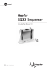
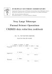
Electrical Power Standards
Andrzej Olencki, Jan Szmytkiewicz, and Krzysztof Urbański
Abstract – In the University Zielona Gora (Poland) and Calmet Ltd, a Three Phase Power and Energy Calibrator and
Tester – Portable Electrical Power Standard was developed
for the calibration and test of a wide range of electrical metering instrumentation. This paper gives a summary of the theoretical and practical details of the project.
Index Terms – Calibrators, Power Quality Measurements,
Energy Meter testing, Protection Relay Test Set, automated
calibrations
I. INTRODUCTION
Typical multifunction calibrators can generate only one quantity
at time – voltage or current. For many applications are needed
precision sources with more than one channel with accurately
generated value of voltage or current [1]. Practically in the laboratories are used two or six channels calibrators. The so-called Single Phase Power Calibrator (SPPC) has two outputs and can generate at the same time AC voltage and current. Also the phase angle between them can be set with high accuracy, so we get possibility of power simulation. The six channels version can generate
three voltages shifted usually by 120° and 240° or with programmed value of angle between voltages and three currents
shifted like the voltages plus an additional phase shift between the
voltage and the current. Such system, called the Three Phase
Power Calibrator (TPPC), allows for a three phase power network
simulation.
The SPPC and TPPC can be applied for adjustment and testing
measurement equipment, especially electricity meters and power
network analyzers [2]. They can generate reference vectors of the
voltage and current which are shown in Fig. 1.
U1
I1
U1; U2; U3
I1; I2; I3
ϕ1; ϕ2; ϕ3
∠
) U2;U1
) U2;U1
∠
∠
) U3;U1
ϕ1
) U3;U1
∠
I3
U3
ϕ3
phase voltage
phase current
phase shift
angle shift between voltage U2
and U1
angle shift between voltage U3
and U1
ϕ2
I2
U2
Fig. 1. Vector diagram of the TPPC output
II. TPPC DEVELOPMENT
History of the TPPC development is shown in Table 1. First in
the World TPPC was introduced in 1976 (the 800 by ROTEK
USA [3]). Probably the first in the Europe TPPC was developed
by our team and was introduced in 1988 (the SQ33 by LUMEL
Poland, actually a product named Inmel 33). The ROTEK 800 was
developed as the SPPC in single case, which may be configured to
operate in single or multi-phase configuration. The complete three
phase system comprises three cases of the SPPC (the construction
version 3xSPPC=TPPC). This design solution ROTEK is used in
the models 8000 and 8100 [11] and FLUKE used in the model
6100A [4]. The SQ33 calibrator was developed as the TPPC in
single case (the construction version 1xTPPC=TPPC). Our experience with this construction version (light weight and small dimensions, simple and economy construction) made possible to develop
the first portable TPPC with current range up to 100A introduced
in 2006 (model C300 by CALMET Poland [5]).
Table 1. Development of the TPPC
IntroConduc- Model
Weigh
struction
name
t [kg]
tion
date
Rotek
1976
3 case
800
Lumel
1988 SQ33 /
1x45
1 case
+P
Inmel
=45
33
Calmet
1993
3x14
C233 3 case
+P
=42
C233B
Rotek
1995
3 case
8000
Fluke
2003 6100A
+P 6130A/ 3 case 3x30
80A
=90
2005 Inmel
1x45
1 case
+A
8033
=45
Rotek
?
8100
+P 8100-3- 3 case 3x25
P
=75
2006 Calmet
1x32
1 case
+P
C300
=32
P – actually produced
Current
range
[A]
Feed- Errors @ 230V/5A/50Hz
back
δP@
∆ϕ
δI
con- δU
PF=1
[ppm]
[ppm]
[°]
verter
[ppm]
A/A
50
A/A
608
700
2150 0,320
100
A/A
1800
700
2500 0,500
A/D
279
154
260
A/D
520
600
1087 0,100
A/D
135
144
126
0,003
A/A
509
520
500
0,100
A/D
80
50
55
100
0,003
Table 1 consists of the following modern Electrical Power Standards (EPS):
• the FLUKE 6100A model high accurate EPS for stationary
utilization,
• the ROTEK 8100 model high accurate EPS for stationary
utilization,
• the CALMET C300 model medium accurate and economy
EPS for portable and stationary used.
The modern EPS is a TPPC with additional features:
• Power Quality Source (PQS) function enables:
o generation of special voltage and current waveforms
(harmonics, interharmonics and special shapes functions),
o simulation of voltage and current variations as a function
of time (ramp functions),
• Automatic Test System (ATS) function for checking of electricity meters, measurement of industrial transducers, current
clamps, current transformers and protection relays, in a fully
automatic way (impulse counter, AC/DC voltage/current
measurement and timer functions).
III. EPS AS A POWER QUALITY SOURCE
The EPS provides the functions required for a full test of power
quality meters with compliance to the requirements of standards
defining power quality measurement methods such as EN 610004-30. To both the voltage and current of the reference vector diagram in Fig.1 may be added Harmonics, Interharmonics (compliance to the EN 61000-4-7) and even Fluctuating Harmonics or
Notching. In the addition to the values of amplitude and phase of
harmonics (frequency, amplitude and phase of interharmonics)
programmed by the user, the EPS can show calculated values of
Crest Factor CF, Shape Factor SF, Total Harmonic Distortion
THD, Total Distortion Factor TDF and Total Interharmonic Distortion TID. Using a Ramp function, both the voltage and current
outputs can be configured to reproduce Dips, Swells, Interruptions
and Flicker Pst or Plt coefficients (compliance to the EN 61000-415) independently on the voltage and current outputs.
Additionally, the EPS provides specific wave shapes such as
those defined by the EN 61036 and EN 50470 for energy meters,
for example Phase Fired or Burst Fired signals.
Most of those signal types are available simultaneously, so it is
possible to get very complex signals.
Error Err
+∆XLIM
0,4
0,3
0,2
0,1
XM
0,0
-0,1 0
-0,2
1
2
3
4
5
6
7
8
9
10
−∆XLIM
-0,3
-0,4
IV. EPS AS AN AUTOMATIC TEST SYSTEM
The idea of a connection TPPC and additional meters with a
computer equipped with specialized ATS software gives a new
kind of device – Three Phase Power Automatic Test System. In
Fig. 2 this calibration and test system, with the C300 EPS, is presented. This system consists of the C300 EPS, PC with Calpro 300 Software and Device Under Test (DUT). The DUT may
be an electricity meter or measurement transducer, current clamp,
current transformer or protective relay. The C300 EPS has a precision TPPC and a set of additional inputs and meters:
•
the impulse counter for counting the impulses from electricity
meters,
•
the U/I meter – a DC voltmeter for measuring the signals
from industrial measurement transducers or DC current
clamps and an AC ammeter for measuring the signals from
AC current clamps or current transformers for measurements,
•
the timer for the output state sensing from protective relays
[6].
Computer
with
Calpro 300
Software
C300
Electrical Power Standard
Device Under Test
TPPC
Response time t R [s]
100,000
1,000
Electricity
Meter
U/I Meter
Measurement
Transducer
tRMIN
0,100
0,010
0,001
1
10
100
XM
Threshold TH
7
6
5
4
3
2
1
0
-1
-2
-3
-4
-5
-6
-7
THMAX
THMIN
-5
Impulse
Counter
tRMAX
10,000
-4
-3
-2
-1
0
1
2
3
4
Parameter
P
5
Fig. 3. Characteristics of the DUT: (a) error curves, (b) response
time curves, (c) threshold values curves for example the R-X dia-
Current
Clamps
Current
Transformer
Timer
Protective
Relay
gram of any distance relay
Error characteristics (Fig. 3a) are measured by means of steady
state testing. Output quantities can either be entered in the classical way as voltage, current, phase angle values, or by using continuous step/ramp modes. In this test the TPPC of the EPS works
in a static mode with extremely high accuracy. The test results are
correct for the following requirements:
− ∆X LIM ( X M ) < Err ( X M ) < + ∆X LIM ( X M )
Fig. 2. Fully Automatic Test System with the C300 EPS
This system can be used for measurements of three kinds of
calibration characteristics in a fully automatic way:
•
error curves (in Fig. 3a) of electricity meters, measurement
transducers, current clamps and measurement transformers,
•
response time (trigger time) curves (in Fig. 3b) of protective
relays, ,
•
threshold values (trigger level) curves (in Fig. 3c) of protective relays.
(1)
where XM is the measured value, that is generate by the EPS and
∆XLIM(XM) is limit of errors.
There are many different methods available for the relay tester
depending on testing equipment features [6]. Steady state testing
including continuous step/ramp mode operation is provided for
finding limiting values, such as pick up and drop off, or starting of
a relay. It is usually used for threshold value curve tests of the relays with a single protection function and with only a single zone
of protection. More elegant dynamic testing, including pulse
ramping [7], dynamic on/off, dynamic simple and dynamic complex [6] methods, is used to determine response time curves (see
Fig. 3b) of the relays and threshold value curves of all relays including multi-zone distance relays. In this test the TPPC of the
EPS works in dynamic mode with extremely short response time.
The C300 EPS uses the static and dynamic on/off method for de-
termine of the relay's protection curves. In dynamic on/off testing
a pretest value is zero and it is suddenly (with 0,001 second response time for C300 EPS) increased to the test value, for example
up to 100A. The test results are correct for the following requirements:
t RMIN ( X M ) < t R ( X M ) < t RMAX ( X M )
(2)
and
TH MIN ( X M ) < TH ( X M ) < TH MAX ( X M ) .
(3)
The error, response time and threshold values characteristics can
be presented as a graph or a table. Efficient testing and performance analysis require well-defined limit values ∆XLIM in Fig. 3a
and recommended protection curves and limit values tRMIN , tRMAX ,
THMIN , THMAX in Fig. 3bc.
V. EPS’s PRINCIPLE OF OPERATION
Fig. 4 presents a circuit block diagram of the SPPC. The structure can be divided into a digital part with a control unit CU and
an analog-to-digital part. This part consists of a generator G, a
phase shifter PS, a voltage output stage VOS and a current output
stage COS. From the control unit to the digital-to-analog part of
the calibrator are connected signals as follows: the setting of a
voltage RMS value (U), the setting of a current RMS value (I), the
setting of a phase shift of a fundamental frequency (ϕ), and the
setting of a fundamental frequency (f). Optionally, the control unit
may also permit the user to define a specific wave shape of the
voltage and/or current, number, amplitude and phase of harmonics, frequency, amplitude and phase of interharmonics on the voltage and current outputs.
AU/D
Σ
setting U
AU/A
U
VOS
setting f
G
AI/D
CU
setting ϕ
Σ
AI/A
PS
setting I
Σ
Digital part
I
COS
ϕ/D
Digital-to-Analog part
Fig. 4. Structural scheme of a SPPC
At the calibrator’s terminals, active power is simulated according to the equation:
P = U ⋅ I ⋅ cosϕ
(4)
with error given by:
δP = δU +
∆U
U
+ δI +
∆I
I
+
cos(ϕ + ∆ϕ ) − cos ϕ
cos ϕ
(5)
where δU, ∆U represent the multiplicative and the additive part of
the voltage error, δI, ∆I represent the multiplicative and the additive part of the current error and ∆ϕ is the error of the phase shift.
To minimize the active power error δP (5), in the SPPC are used
the close loops for stabilisation of the voltage, current magnitude
and phase shift value.
Two typical ways of stabilising the voltage and current magnitudes are illustrated in Fig 4. In one way, a feedback path consists
of an Analogue-to-Analogue Converter AU/A in the voltage feedback and an AI/A in the current feedback. This technology named
as Analog Technology is implemented in the Calmet C300 EPS
(in Table 1 the column named as "Feedback converter") with using modern RMS/DC converters, DAC's in adders Σ for comparing the setting with the feedback signals from proportional plus integral feedback control system (with using PI controller) and with
digital correction of a nonlinearity. In the other, the feedback path
consists of an Analogue-to Digital Converter AU/D in the voltage
feedback and an AI/D in the current feedback. This technology
named as Digital Technology is implemented in the ROTEK 8100
and FLUKE 6100A EPS with using modern DSP processors and
is patented by Rotek in 1997 [8] and Fluke in 2005 [9].
Practically in all modern EPS's, digital technology with DSP
processors are used for the phase angle and the angle between
voltages stabilisation. The phase angle between the voltage U and
the current I from the calibrator outputs is converted by the phase
shift angle converter ϕ/D to digital code and is compared with the
phase angle setting. The result of the comparison, as a phase error,
is added in the adder Σ to the main signal setting ϕ. This idea was
patented by authors in 1994 [10] and is implemented in the Polish
SPPC and TPPC. In the first Polish TPPC series SQ33 is used microprocessor's technology, and in the INMEL 8033 and
CALMET C300 is used DSP technology (see Table 1).
VI. ALTERNATIVES TO THE EPS
For many applications there is a need a precision multi channel
source of AC voltage, current and phase angle, for example in the
calibration and test of the measurement transducers and meters of
power network parameters, electricity meters, current transformers, protection relays, and in the recent years power quality meters. Traditionally, for calibration each kind of those devices are
used in different kinds of measurement instruments. The measurement transducers and meters of power network parameters and
power quality meters, recorders and analysers are tested by means
of the power calibrators (TPPC from Table 1).
Electricity meters calibrations are mainly performed by using
the energy comparison method (as named the reference meter
method too). A known amount of energy generated from a three
phase phantom power is simultaneously supplied to a reference
electricity meter and the DUT. The modern reference electricity
meters consists of a device for counting pulses from the DUT,
which calculates and indicates an error of the DUT. It can also
display the phase diagrams for quick orientation in the positions of
the generated signals and to calculate and display the frequency
spectrum of the generated signals. The three phase portable test
systems for the automatic testing of a single energy meter, which
consists of an integrated three phase voltage and a current source
and a three phase reference meter are produced by a few firms, for
example RADIAN, ZERA, MTE. This system is named as the
Meter Test System, Energy Meter Tester, Test Bench.
For electricity meter calibrations may be used the energy calibrator method. In this applications, the calibrator is equipped with
the Impulse Counter (see Fig. 2) to receive pulses from the DUT
and it is then able to calculate energy recorded by the DUT (according to the meter constant entered by the user), compare this
against energy it has delivered, then calculates and display DUT
errors. The TPPC can be used in following testing modes: the
Count/Time Mode for verify energy meters from their inputs to
the impulse output and the Energy Packet Mode (also known as
Dose Mode) for verify energy meters from their inputs to the
counting device. In the Dose mode, the power from the calibrator's
output is generated during set period of time to deliver the requested amount of energy to the DUT.
The energy calibrator method for testing electricity meters with
the describe modes are used for a long time. Firstly it was implemented 30-ty years ago in the ROTEK 800 and 20-ty years ago by
authors in the LUMEL’s SQ33 TPPC. Electricity meter testing
typically falls into the following categories:
•
type testing/approval and service testing/calibration many
different types in small amount of the DUT with recommended to use the EPS or a single position Test Bench,
•
service testing/calibration and particularly manufacturing
testing with recommended to use a multi position Test
Bench.
Current transformer testers (also known as the Current Transformer Test Set or Test Bench) are used by electric utilities to verify accuracy of the transformers for measurement of an electric
energy. The current generating range should be from 100A up to
2000A for measure an instrument transformer ratio and phase angle errors. The C300 high current EPS may be used only to 100A200A-300A primary current transformer testing in their full current range. In this applications, the calibrator is equipped with 5A
or 1A current range the I Meter (in Fig. 2) for secondary current
measurement.
Multi turn coils (with 5/10/20/50/100/200 turns) in conjunction
with the EPS or a single output current calibrator are used as a tool
for the calibrating AC current clamps up to 3000A. In this applications, the calibrator is equipped with the AC I Meter for current
output clamps and with the AC U Meter for voltage output clamps
(in Fig. 2).
Portable protection relay test sets for the automatic testing of all
kinds of relays are produced by a few firm, for example ISA,
MEGGER, OMICRON. Some features required to test over 90%
of relay applications include [6]:
•
a three phase voltage and current source with independent
controls for a phase angle, magnitude and frequency,
•
at least 25 Amps per channel in the three phase configuration
and 75 Amps in the parallel single phase configuration,
•
a normally open/closed and/or voltage sensing input for timing,
•
at least one normally open/closed output contact to simulate a
breaker status,
•
independent pre-fault and fault modes for dynamic testing.
The perfect test set features include a multiphase source with 4 independent voltage and 7 independent current sources up to 50
Amps per phase in a three phase system.
The TPPC with a long setting time typically 1 second, may be
used for the pick up tests in continuous step/ramp mode operations
and for timing tests in the dynamic on/off mode. In this applications, the calibrator is equipped with the Timer for relay state
sensing (in Fig 2).
VII. FUNCTIONALITY OF THE EPS
Advanced relay testers are designed for calibrating of electrical
apparatus, such as: energy meters, instrument transformers, transducers, power quality meters. Comparison table (Table 2) of the
EPS functions shows, that the TPPC and the advanced relay testers are physical models of an electrical power network designed to
the automatic calibration and test of a wide range electrical metering instrumentation.
Table 2. Comparison table of the EPS functions
Function
Harmonics
Fluctuating
Harmonics
Interharmonics
Notching
Dips
Swells
Interruptions
Flicker
Calibrators
Relay testers
Calmet
ISA
Omicron
Rotek
Fluke
DRTS6
CMC
C300
8100
Protection 256plus
Three
6100A
Power
ElectriPhase
Relay Test Protection
and Encal
Power
Set and Relay Test
ergy
Measure- Set and
Calibrator Power
CalibraStandard
and
ment Sys- Universal
tor
tem
Tester
Calibrator
PQS functions
√
√
√
√
√
√
√
√
√
√
√
√
√
√
√
√
√
√
√
√
√
√
√
√
√
√
√
√
√
√
√
√
√
Energy Meters
Transducers
Transformers
Clamps
Relays
√
√
√
√
√
ATS functions
√
√
-
√
√
√
√
√
√
√
√
Harmonics, interharmonics and notching functions are generated
by their adding to the magnitude of the voltage or current. Fluctuations, dips, swells, interruptions and flicker functions are realised
by using the step or ramp operations for one or more parameters as
voltage/current magnitude, frequency, phase angle or harmonics
simultaneously. High accuracy devices as the ROTEK 8100 or the
FLUKE 6100A traditionally have a large size of a front panel and
may be equipped with a large display and a keyboard. Medium accuracy and small size portable devices as the CALMET 300,
ISA DRTS6 or OMICRON CMC 256 plus with many additional
terminals needed for realisation the ATS functions, particularly for
relay testing, are designed to the programmed only from a special
PC software with a user interface allowing manual and full calibrations of the DUT. Features of the Calibrators and Testers become similar. Names of this devices become similar, for example
the Protection Relay Test Set CMC 256 names as the Universal
Calibrator too and the Three Phase Power Calibrator C 300 names
as the Tester too.
VIII. CONCLUSION
The C300 Three Phase Power Calibrator has been designed and
introduced as portable medium 0,05% accuracy, comprehensive
and flexible source of electrical power signals. This single instrument in many applications replaces the complicated high weight,
big size and high cost combinations of individual Single Phase
Calibrators and Auxiliary Power Amplifiers required to calibrate
wide range of electrical metering instrumentation up to 100A in
three phase configurations.
REFERENCES
[1] A. Carullo, F. Ferraris, M. Parvis and A. Vallan, "Phantom power generator for the calibration of wattmeters in distorted environments," in Proc.
IMECO TC-4 Symp. Development in Digital Measuring Instrumentation
and 3-rd Workshop ADC Modelling and Testing, Naples, Italy, 1998,
pp.67-71.
[2] D. Coombes, "Improving accuracy of power quality measurements," Fluke
Precision
Measurement
Hurricane
Way,
Norwich,
UK,
http://assets.fluke.com.
[3] About Us. Rotek, USA, http://www.rotek.com.
[4] The Fluke 6100A Electrical Power Standard. Fluke, USA,
http://ca.fluke.com.
[5] Three phase power calibrator and power engineering apparatus tester.
User's manual. Calmet, Poland, http://www.calmet.com.pl.
[6] Ch. Werstiuk, The relay testing handbook: Principles of relay testing. Valence Electrical Training Services, USA, 2008.
[7] B. Bastigkeit, Testing the pick-up value of overlapping protection elements/functions without changing the parameter settings: Omicron Electronics – User conference, 2002.
[8] A. Gubisch, J. West, P. Miljanic, P. Lualdi, "Precision voltage/current/power source," United States Patent US 5,642,300, Jun. 24,
1997.
[9] P. Harbord, A. Fields, "Method and apparatus for generating an electronic
test signal," United States Patent US 6,944,569, Sep. 13, 2005.
[10] A. Olencki, K. Urbanski, "Three phase calibrator," Polish Patent PL
163006, Jan. 31, 1994.
[11] Model 8100 Power and Energy Calibrator. Operator manual. Rotek, USA.