1
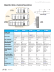
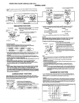
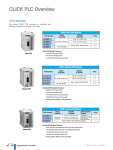
I/O Module Selection & Wiring Guidelines 15 In This Chapter. . . . — I/O Selection Considerations — Sinking and Sourcing Circuits — DL305 Input Module Configuration Chart — DL305 Output Module Configuration Chart — Configuration #1 DL305 DC Current Sourcing Input Module — Configuration #2 DL305 DC Current Sinking/Sourcing Input Module — Configuration #3 DL305 DC Current Sinking Input Module — Configuration #4 DL305 AC/DC Input Module — Configuration #5 DL305 AC Input Module — Configuration #6 DL305 DC Current Sinking Output Module — Configuration #7 DL305 DC Current Sourcing Output Module — Configuration #8 DL305 AC/DC Current Sink/Source (Relay) Output Module — Configuration #9 DL305 AC Output Module — Solid State Field Device Wiring to DC Input Modules — Derating Characteristics — I/O Wiring Guidelines — Fuse Protection I/O Module Selection Criteria 5--2 I/O Module Selection & Wiring Guidelines I/O Selection Considerations I/O Module Selection The DL305 product family offers various types of I/O modules for interfacing many different field devices to the PLC system. There are several electrical characteristics that should be considered when choosing the proper I/O module for a field device or for obtaining required system performance. Electrical characteristics for discrete input modules and discrete output modules are discussed in Chapters 6 and 7. The DL305 family also offers several specialized modules such as analog, ASCII BASIC modules, network interface modules, high speed counter modules, etc. These modules have their own manuals, so if you are using them you should supplement this manual with the manual specifically designed for the special module. Sinking and Sourcing Circuits I/O Module Selection & Wiring Guidelines The charts on the following page supply information on the current sinking and current sourcing configurations using DL305 discrete I/O modules. If you have a question about the type of device required to connect to a particular module please refer to the following charts. The charts show nine common input and output module configurations. Match the module part number you are considering to the applicable configuration(s) to ensure the module type will work in your application. For additional clarification we have included nine diagrams depicting the configurations listed in the charts. These diagrams show the module category, type of device and how they are connected to each other. The diagrams and two examples of wiring a solid state switch to an input module follow the charts on the next page. DL305 User Manual, Rev. D I/O Module Selection & Wiring Guidelines DL305 Input Module Type D3--16ND2--1 D3--16ND2--2* D3--16ND2F Config #1 DC Current Sourcing Input Config #2 DC Current Sink/Source Input Config #4 AC/DC Input Config #5 AC Input F3--16ND3F D3--08ND2 Config #3 DC Current Sinking Input D3--08NA--1 D3--08NA--2 D3--16NA D3--08NE3 D3--16NE3 I/O Module Selection Criteria DL305 Input Module Configuration Chart 5--3 DL305 Output Module Configuration Chart DL305 Output Module Type D3--04TD1 D3--08TD1 Config #6 DC Current Sinking Output D3--16TD1--2* D3--16TD2 D3--08TA--1 D3--08TA--2 F3--16TA--1* F3--16TA--2 D3--16TA--2 D3--08TR F3--08TRS--1 F3--08TRS--4 D3--16TR D3--04TAS F3--08TAS* F3--08TAS--1 * Obsolete DL305 User Manual, Rev. D I/O Module Selection & Wiring Guidelines F3--08TRS--2 Config #9 AC Output D3--08TD2 D3--16TD1--1 Config #7 Config #8 DC Current Sourcing AC/DC Current Output Sink/Source Output I/O Module Selection Criteria 5--4 I/O Module Selection & Wiring Guidelines Configuration #1 DL305 DC Current Sourcing Input Module Sourcing Input Module Device Output Device Common Sinking Field Device Device Common Sinking Field Device Current Flow Device Output Module Input Current Flow Current Flow -- + DC Supply Module Input Note: Some modules may have their own internal power supply and do not require an external supply as shown here. See individual input voltage specifications to find out power supply requirements. Module Common Configuration #2 DL305 DC Current Sinking/Sourcing Input Module Device Common Sourcing Field Device Sink/Source Input Module Device Output Current Flow Current Flow + -- Module Input Module Common } Current Sinking Input Configuration I/O Module Selection & Wiring Guidelines DC Supply Device Common Sinking Field Device Device Output Current Flow Current Flow -+ DC Supply DL305 User Manual, Rev. D Module Input Module Common } Current Sourcing Input Configuration I/O Module Selection & Wiring Guidelines Device Common Sourcing Field Device Device Common Sourcing Field Device Sinking Input Module Device Output Current Flow Device Output Current Flow Current Flow + I/O Module Selection Criteria Configuration #3 DL305 DC Current Sinking Input Module 5--5 Module Input Module Input Module Common -- DC Supply Configuration #4 DL305 AC/DC Input Module Device Common Field Device AC/DC Input Module Device Output -- + Or Module Input Module Common + -DC Supply Field Device Device Output Module Input Module Common AC Supply DL305 User Manual, Rev. D I/O Module Selection & Wiring Guidelines Device Common I/O Module Selection Criteria 5--6 I/O Module Selection & Wiring Guidelines Configuration #5 DL305 AC Input Module Device Common Field Device Device Output AC Input Module Module Input Module Common AC Supply Device Common Field Device Device Output Module Input Module Common I/O Module Selection & Wiring Guidelines AC Supply DL305 User Manual, Rev. D I/O Module Selection & Wiring Guidelines Load Device Common Sourcing Field Device Device Common Sourcing Field Device Sinking Output Module Device Input Current Flow Device Input Current Flow Module Output I/O Module Selection Criteria Configuration #6 DL305 DC Current Sinking Output Module 5--7 Module Output Load + -DC Supply Current Flow Module Common Configuration #7 DL305 DC Current Sourcing Output Module Load Device Common Sinking Field Device Device Common Sinking Field Device Sourcing Output Module Device Input Current Flow Device Input Current Flow Module Output Module Output Load + Current Flow Module Common DC Supply DL305 User Manual, Rev. D I/O Module Selection & Wiring Guidelines -- I/O Module Selection Criteria 5--8 I/O Module Selection & Wiring Guidelines Configuration #8 DL305 AC/DC Current Sink/Source (Relay) Output Module Load Device Common Field Device Relay Output Module Device Input -- + Or Module Output Module Common + -DC Supply Load Device Common Field Device Device Input Module Output Module Common AC Supply Configuration #9 DL305 AC Output Module Load Device Common Field Device Device Input AC Output Module Module Output Module Common AC Supply I/O Module Selection & Wiring Guidelines Load Device Common Field Device Device Input Module Output Module Common AC Supply DL305 User Manual, Rev. D I/O Module Selection & Wiring Guidelines NPN Field Device Example 24VDC + -+ I/O Module Selection Criteria Solid State Field Device Wiring to DC Input Modules 5--9 D3--08ND2 Input Module Sensor Input Output -- + Optical Isolator -Common (NPN) Current Sinking Field Device Current Sourcing Configuration PNP Field Device Example D3--16NE3 Input Module 24VDC + -+ Sensor Common Output Input -- Optical Isolator Current Sinking Input Module I/O Module Selection & Wiring Guidelines (PNP) Current Sourcing Field Device DL305 User Manual, Rev. D I/O Module Selection Criteria 5--10 I/O Module Selection & Wiring Guidelines Derating Characteristics The DL305 input and output module operating specifications change depending on ambient temperature. The I/O specifications have a derating chart for each module which shows functionality in respect to ambient temperature. The example below shows a derating curve for a D3--08ND2 discrete input module where the operating specifications do not change within the specified temperature operating range. Points 8 6 4 2 0 0 32 10 50 20 68 30 86 40 104 50 122 60°C 140°F Ambient Temperature (°C/°F) The example below shows a derating curve for a D3--16TD--1 discrete output module where the operating specifications are affected depending on ambient temperature. Points 16 0.25A 0.35A 12 I/O Module Selection & Wiring Guidelines 8 0.5A 4 0 0 32 10 50 20 68 30 86 40 104 Ambient Temperature (°C/°F) DL305 User Manual, Rev. D 50 122 60°C 140°F I/O Module Selection & Wiring Guidelines 5--11 General Considerations The following information is to give you a general idea on how to wire the different types of modules in the DL305 system. For specific information on wiring a particular module refer to the specification sheet in the appropriate I/O chapter. Consider the following guidelines when connecting the field wring. 1. There is a maximum AWG the modules can accept. You can uses a smaller AWG than is noted in the table below. Module type Maximum AWG 8 point 12 16 point 16 I/O Module Selection Criteria I/O Wiring Guidelines 2. Always use a continuous length of wire, do not combine wires to attain a desired length. 3. Use the shortest possible cable length. 4. Use wire trays for routing where possible 5. Avoid running wires near high energy wiring. 6. Avoid running input wiring in close proximity to output wiring where possible. 7. To minimize voltage drops when wires must run a long distance , consider using multiple wires for the return line. 8. Avoid running DC wiring in close proximity to AC wiring where possible. 9. Avoid creating sharp bends in the wires. Wiring the Different There are three main types of module faces for the DL305 I/O. These module faces are: lift covers over terminal blocks, flip covers over terminal blocks and D--shell Module Types compatible sockets. If the module you are using has a cover you can remove the cover either by lifting from the bottom or by flipping the door open. Some of the modules have removable terminal blocks. These modules can be recognized by the squeeze tabs on the top and bottom of the terminal block. To remove the terminal block, press the squeeze tabs and pull the block away from the module. WARNING: For some modules, field device power may still be present on the terminal block even though the PLC system is turned off. To minimize the risk of electrical shock, check all field device power before you remove the connector. Squeeze Tab Removable Cover Squeeze Tab Removable Terminal Block DL305 User Manual, Rev. D I/O Module Selection & Wiring Guidelines D--shell Connector I/O Module Selection Criteria 5--12 I/O Module Selection & Wiring Guidelines Fuse Protection To help avoid blowing the internal module fuses, we suggest you add external fuses to your I/O wiring. A fast blow fuse with a lower current rating than the I/O module fuse can be added to each common. Or, you can add a fuse with a rating of slightly less than the maximum current per output point to each output. Refer to the I/O module specification sheets to find the maximum current per point or per common for output modules. Adding the external fuse does not guarantee the prevention of module damage, but it will provide added protection. External Fuse Example External Fuses (shown with DIN Rail, Fuse Blocks) I/O Module Selection & Wiring Guidelines WARNING: For modules which have soldered-in or non-replaceable fuses, we recommend that you return the module to us and let us replace your blown fuse(s) since the module fuses are attached to the board and disassembling the module will void your warranty. DL305 User Manual, Rev. D