1
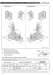
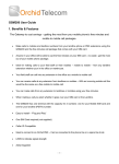
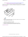
Installation and User’s manual Thank you for choosing an Esse-ti product This product has been especially designed for easy operation. It has been manufactured with perfect workmanship using suitable materials for long-lasting performance. All Esse-ti products are subjected to extensive reliability and operational testing in our laboratories in order to provide total guarantee for the user. The User shall be responsible for defects arising from the use of the product. Esse-ti shall only be responsible for defects according to and within the limitations set by the Presidential Decree dated 24/05/1988 no. 224 (fulfilling the EEC directive no. 85/374 on the harmonisation of statutory and administrative regulations of the Member States on the liability for damages arising from defective products under art. 15 of Law no. 183 of 16 April 1987). Esse-ti reserves the right to modify the characteristics of the products at any time without prior notice. TABLE OF CONTENTS GENERAL INSTRUCTIONS FOR THE INSTALLER .................... 4 General Notes................................................................................. 4 Making the Installation .................................................................. 5 DESCRIPTION .................................................................................. 6 INSTALLATION ............................................................................... 7 Inserting the SIM card ............................................................................. 8 Inserting the antenna ................................................................................ 8 PROGRAMMING.............................................................................. 9 CONNECTIONS .............................................................................. 10 Helpy L300 / Helpy L300 TL ................................................................ 10 Helpy L200 / Helpy L200 TL ................................................................ 10 ST60 / ST61 / Helpy Quick / Helpy Quick-TL / Helpy Vox ................ 10 ST56 / Helpy Star................................................................................... 11 GSM Combi board ................................................................................. 11 STARTING ...................................................................................... 12 Test call .................................................................................................. 13 Module mounting operations ................................................................. 13 GSM200 installation recommendations ................................................ 14 SIGNALLING .................................................................................. 15 LED indicating device operation status (RED) ..................................... 15 LED indicating GSM signal strength (GREEN) ................................... 15 GENERAL INSTRUCTIONS FOR THE INSTALLER GENERAL NOTES Carefully read the notes contained in this section as they provide important information on the correct safe installation, use and maintenance of the product. The product must be EXCLUSIVELY used for the purpose it was designed for. Esse-ti shall not be responsible for damages arising from improper use. The product has been designed in compliance with the regulations in force and must be installed in systems that comply with the provisions of law. Always disconnect the product from the power supply mains before carrying out any operation either inside or outside the product (cleaning, maintenance, etc.). Always refer to an authorised assistance centre for repair. Install the product in a well-ventilated place, making sure not to obstruct the ventilation slots. Beware of symbols showing lightening with arrow inside a triangle since they indicate the presence of dangerous voltage. Beware of symbols showing an exclamation mark inside a triangle since they indicate potentially dangerous or even lethal situations that require utmost attention. Do not use the product in association with other electric or electronic devices that were not especially designed to be used with it. Do not install the product in potentially explosive environments. Make sure that the product has been installed as required. Page 4 Do not introduce objects, liquids or powders inside the product. Do not use sprays inside the product. Do not open the product case since it does not contain any userserviceable parts. If necessary, contact an authorised assistance centre. Packing components (such as plastic bags, foam polystyrene, etc.) must be kept out of the reach of children because potentially dangerous. MAKING THE INSTALLATION Internal telephone installations must be carried out by specialised personnel. The installation and connection of telephone terminals to the telecommunications network that do not comply with the regulations in force is not permitted. Page 5 DESCRIPTION The GSM200 module can be used in conjunction with the following Esse-ti devices: Elevator alarm systems: Helpy L300 Helpy L300 TL Helpy L200 Helpy L200 TL ST60 ST61 Helpy Quick Helpy Quick-TL Helpy Vox ST56 Helpy Star GSM Combi Board For the correct operation of the module , a standard SIM Card is required. This manual describes the GSM200 installation procedure. For other instructions, please refer to the elevator alarm system user manual or to the GSM Combi user manual. Page 6 INSTALLATION A B C D Remove the cover. ANTENNA connector LED indicating signal strength (green) and LED indicating device operation status (red) SIM CARD housing RJ45 for module connection to Esse-ti elevator alarm systems or GSM Combi board Page 7 Inserting the SIM card Before inserting or replacing the SIM card, always make sure that the module has been disconnected from the mains and that no electrostatic discharge is present in order to avoid damaging it. Take all necessary measures to avoid electrostatic discharge. Shift the SIM card housing cover upward and lift it. Carefully slide the SIM card in its housing cover. Lower the SIM card housing cover and shift it downward until it blocks. WARNING The SIM Card must have the PIN code DISABLED. If the Sim card has the PIN Code enabled it is necessary to disable it by means of a normal mobile phone. Close the module cover. Inserting the antenna Screw the antenna in to the connector on the top of the module. WARNING NEVER connect GSM200 module without having installed the antenna. The module may damage. Page 8 PROGRAMMING When using the GSM200 module for connection with any Esse-ti alarm system, please make sure the parameter “Programming the type of telephone line” has been adequately set in the specific alarm system. Lift the local telephone handset of the elevator alarm system. Dial: < Installer password > (by default: ). Set the type of GSM200 line: Exit programming: < Installer password> (by default: ). Page 9 CONNECTIONS Helpy L300 / Helpy L300 TL Make sure that the jumpers JP11 and JP12 located on the Helpy L300/Helpy L300 TL are in position 2-3 (towards the RJ45 connector). Insert the provided cable (pin-to-pin cable) in to the two RJ45 connectors located on the Helpy L300/Helpy L300 TL and GSM200 module. In order to reach longer distances (up to 100m), please use a cat.5 or higher cable. Helpy L200 / Helpy L200 TL Make sure that the jumper JP5 located on the Helpy L200/Helpy L200 TL is in position 2-3 (towards the RJ45 connector). Insert the provided cable (pin-to-pin cable) in to the two RJ45 connectors located on the Helpy L200/Helpy L200 TL and GSM200 module. In order to reach longer distances (up to 100m), please use a cat.5 or higher cable. ST60 / ST61 / Helpy Quick / Helpy Quick-TL / Helpy Vox Make sure that the two jumpers, located near the RJ45 connector on the ST60/ST61/Helpy Quick/Helpy Quick-TL/Helpy Vox, are positioned towards the RJ-45 connector. Page 10 Insert the provided cable (pin-to-pin cable) in to the two RJ45 connectors located on the ST60/ST61/Helpy Quick/Helpy QuickTL/Helpy Vox and GSM200 module. In order to reach longer distances (up to 100m), please use a cat.5 or higher cable. ST56 / Helpy Star Make sure that, on the ST56/Helpy Star, jumpers are inserted in the larger connector for optional PSTN line board. Insert the provided cable (pin-to-pin cable) in to the two RJ45 connectors located on the ST56/Helpy Star and GSM200 module. In order to reach longer distances (up to 100m), please use a cat.5 or higher cable. GSM Combi board In order to connect the GSM200 module to the GSM Combi board, refer to the GSM Combi board’s instruction manual. Note: when connected to the GSM Combi board, the green LED (indicating signal strength) located on the GSM200 module is not working. To check the signal strength, check the LED located on the connection board provided with the GSM Combi (CT-624) or the LED located ont he GSM Combi board (POLARIS/SMILE/FOX). Page 11 STARTING After the connection, make sure that the red LED (indicating the device operation status) located on the GSM200 module is switched on and stays lit for a few seconds before it starts blinking. In case the red LED should not be blinking, the GSM module would not be correctly registered to the GSM network provider. Disconnect the GSM200 and make sure that the SIM card has been correctly inserted and no PIN is on. For a correct registration of the GSM200 module you must wait 1 minute’s time. Check the signal strength by means of the green LED located on the GSM200 module (see paragraph:”Signalling”). Note: the signal strength is also indicated by the specific LED located on the elevator alarm system. Note: when connected to the Helpy L200/Helpy L200 TL, the green LED (signal strength) located on the GSM200 module is not working. Check the signal strength by means of the LED indicating the device operation status located on the Helpy L200/Helpy L200 TL (see the Helpy L200/Helpy L200 TL user manual). If the signal strength is good, proceed with a test call and mounting operations (see the following paragraphs). Page 12 Test call Lift the local telephone handset of the elevator alarm system. Dial: < Installer password > (by default: ). (dialing tone) Dial: (dialing tone) Dial: ... (telephone number) Note: wait about 10 seconds after dialling the desired telephone number before a confirmation tone indicates that the call has been forwarded. Module mounting operations Drill two holes with 5mm diameter on the wall at a distance of 50mm. Insert the 2 fischers and screw down until the screws are at a 5mm distance from the wall. Place the GSM200 module onto the two screws. Page 13 GSM200 installation recommendations The module is provided with a 3m. cable. Use a cat.5 or higher cable to connect the GSM200 module at a longer distance (up to 100m). The minimum recommended distance, between the GSM200 module and the elevator alarm system, is 50cm. The GSM200 module must be installed in a location where the radio signal allows for using the GSM system. It is advisable to leave plenty of space around the module for maintenance operations. Do not lay the connection cable near the 230Vac mains. Do not install the GSM200 module outdoors, since it lacks protection devices against weather conditions that can damage the module (water, humidity, etc.). Do not install the GSM200 module near electronic (radio or TV sets, Personal Computers, wired radio systems, etc.) or magnetic (credit cards, floppy disks, etc.) devices that could be subjected to RF interference from the module: recommended distance from the antenna is min. 2.5m. Do not install the GSM200 module near medical devices. Its operation may cause damage to hearing aids or pacemakers. Always make sure that the device operation is permitted in the place of installation (i.e. installation is not allowed in hospitals, airplanes, etc.). WARNING To ensure proper operation, it is recommended not to mount GSM200 module next to metal surfaces. Page 14 SIGNALLING LED indicating device operation status (RED) Normal operation LED indicating GSM signal strength (GREEN) No signal Low signal level Medium signal level High signal level Page 15 GSM200 Rel. dated 25/03/2015