1
Institut für Automatik
Diss. ETH No. 14481
Surface Functional Electrical
Stimulation (FES) Neuroprostheses
for Grasping
Thierry Keller
1
2
Diss. ETH No. 14481
Surface Functional Electrical Stimulation (FES)
Neuroprostheses for Grasping
A dissertation submitted to the
SWISS FEDERAL INSTITUTE OF TECHNOLOGY ZURICH
for the degree of
Doctor of Technical Sciences
presented by
Thierry Keller
Dipl. El.-Ing. ETH
born 9. Mai 1968
citizen of Oberthal (BE)
accepted on the recommendation of
Prof. Dr. M. Morari, examiner
Prof. Dr. V. Dietz, co-examiner
2001
Foreword
Doing research and writing a thesis has a lot to do with curiosity, persistence and
motivation. Curious I was since my early childhood when I was questioning almost
everything and my parents never got tired to explain or to guess the right answer. They
appertain my innermost thank for all the freedom they gave me in making my own
decisions and in supporting me in every sense. Persistence is a necessity for engineers
who want to get things moved and I never lacked of. The third attribute motivation is
where friends, colleagues, and supervisors can really help that a work becomes
successful. And I had not a few:
I would like to thank Jan Schultheiss who brought me into the challenging field of
rehabilitation engineering in offering me to work with him as a research engineer. In this
first phase I was essentially supported by our former technician and my friend Hannes
Wichser who helped me with the design and construction of the first two versions of
electrical stimulators. He motivated me to continue the project after Jan left the group.
My intimate thanks belong to one of my best friends Milos R. Popovic. I learned him to
know as a very professional group leader with both excellent technical and human
expertise. We often spent hours with very vivid discussions about the accomplished
work, the next goals, general concepts, and strategic decisions. I would not be where I'm
now without his advice, help, and support.
Of course, the whole project could not be done without the support and collaboration of
the ETH-ParaCare team, the engineers, researchers, clinicians, and therapists. Such an
intense and close collaboration between the clinical and research staff was only possible
due to the integrative commitment of my co-supervisor Prof. Dr. Volker Dietz, head of
the spinal cord injury rehabilitation center ParaCare, University Hospital Balgrist. It was
always very impressive for me to see and feel how strong he is committed to research,
therapy and medicine and how he acknowledges both the technical and medical efforts.
Special thanks go to Gery Colombo, who besides his own research and developments
was responsible as ParaCare lab leader for the excellent functioning infrastructure and
equipment, and to my teammates Ion Pappas and Sabine Mangold for their contribution
in the FES project. To work in such a research family was and further is a pleasure.
Great support from the medical side I also got from Armin Curt. He always believed in
the potential of FES opened us the way to clinical applications, motivated patients and
therapists to try our prototypes, and educated and provided me with the medical
knowledge necessary for developing assistive and therapeutic devices for SCI subjects.
3
4
On the technical side and for managing the project I was encouraged, supported and
advised by my supervisor Prof. Manfred Morari, head of the Automatic Control
Laboratory, ETHZ. I was specially impressed by his way of leadership, giving his people
enough freedom to evolve own ideas and to put them into practice, but decidedly
intervening if projects were in danger to slip off the track. He always evaluated our
actions from a more general perspective, contributed an additional point of view, and
brought in additional dimensions. Also his humanity and concernment in critical
situations were very formative and exemplary to me.
Besides our group I would like to thank Prof. Dejan Popovic who helped our group with
his enormous knowledge about the field of FES and from whom I learned to separate the
wheat from the chaff. He was always in our favor and provided us with information,
suggestions, and advice.
The last and most intimate thanks belong, as Milos used to say, to my "real boss", my
wife Claudia. She was the person that supported me in all three attributes curiosity,
persistence, and motivation through the thesis. In evening long discussions she prickled
my curiosity, trained my persistence, and enlivened my motivation. She gave me the
strength, the relief, and the necessary spunk.
Abstract
The main objective described in this thesis was to develop systems and methods that use
functional electrical stimulation (FES) to improve the grasp function in spinal cord
injured (SCI) subjects. Such systems are called neuroprostheses for grasping. The
transcutaneous (surface) neuroprostheses were developed for neurologically not stable
SCI subjects and mainly applied during their first rehabilitation at ParaCare, University
Hospital Balgrist, Zurich in a collaboration with the Automatic Control Laboratory of
the Swiss Federal Institute of Technology, Zurich. For these subjects highly flexible
systems are required that are commercially not available. The existing implantable
technology cannot be applied that early.
In a first phase successfully functioning prototypes of neuroprostheses for grasping were
developed. Experiments with SCI subjects demonstrated that the neuroprostheses for
grasping can significantly improve the quality of life of SCI subjects.
Since the first phase established the feasibility of using neuroprostheses for grasping to
effectively improve the SCI subjects' hand function, the project was focussed on
resolving a number of scientific, engineering and clinical questions which stand in the
way of commercially available “attach-and-go” devices that require minimal training,
adaptation, and maintenance. In collaboration with one of the world's leading
manufacturers of electrical stimulators, the Swiss company Compex SA, the goal of
developing a flexible FES device with commercial strength could be achieved.
Specifically, the most important research goals of this thesis project were:
1. The development of a hardware platform (FES system) that facilitates fast
testing of concepts and methods based on FES for the restoration or
improvement of the grasp function in SCI subjects.
2. The development of control strategies that allow the user of the neuroprosthesis
to perform different types of grasps. One of the goals was to explore control
strategies that use electromyographic signals (EMG) from voluntarily activated
muscles during FES to command and/or control the grasp function.
3. The development of new firmware and software programs for an existing,
commercially available electrical stimulator that enabled us to use the stimulator
for FES applications and to build portable neuroprostheses for grasping.
5
6
First clinical and ‘in-field’ tests with the portable neuroprosthesis for grasping proved its
applicability in an early rehabilitation phase. In all SCI subjects a better grasp
performance could be obtained with the system. SCI subjects that had proximal arm
muscle functions but no finger functions became able to grasp, hold and release objects
used in activities of daily living and improved their level of independence. They were
the ideal candidates for using the system chronically as a grasp aid. Incomplete SCI
subjects could mainly profit from the system as a training device. There is strong
evidence that FES training improves their grasp capacity and plays a significant role in
the reorganization of the remaining intact pathways and the plasticity of the central
nervous system. This last result could not be proven, but will be the focus of a future
multicenter study with the developed portable neuroprosthesis for grasping.
Kurzfassung
Die Arbeit beschreibt die Entwicklung von Systemen und Methoden, welche mittels
funktioneller Elektrostimulation (FES) die Greiffunktion von querschnittgelähmten
Personen verbessern. Solche Greifhilfen werden auch als Greifneuroprothesen
bezeichnet. Die hier vorgestellten Greifneuroprothesen wurden speziell für die
Erstrehabilitation von tetraplegischen Patienten entwickelt und am schweizerischen
Forschungs- und Behandlungszentrum ParaCare der Universitätsklinik Balgrist in
Zusammenarbeit mit dem Institut für Automatik der ETH Zürich angewendet. Die
Greifneuroprothesen basieren auf dem Prinzip der Oberflächenelektrostimulation und
unterscheiden sich von kommerziell erhältlichen Systemen durch eine höhere
Flexibilität.
In einer ersten Phase wurden Prototypen für ein stationäres und ein portables System
entwickelt. Versuche mit diesen Prototypen im Rahmen einer Machbarkeitsstudie
zeigten, dass sich mit diesen Greifneuroprothesen die Greiffunktion der Probanden
signifikant verbessern liess.
In einer zweiten Phase richtete sich das Forschungsinteresse auf die Lösung von
wissenschaftlichen, technischen und klinischen Fragen, welche im Hinblick auf eine
mögliche Kommerzialisierung eines FES Systems gelöst werden mussten. In
Zusammenarbeit mit einem der weltweit führenden Hersteller von Neurostimulatoren,
der Schweizer Firma Compex SA, wurde ein vielseitig anwendbares FES System als
Basis für Greifneuroprothesen entwickelt, welches alle Anforderungen der
Neuroprothesen erfüllt.
Die wichtigsten Forschungsziele der Arbeit waren:
1. Die Entwicklung einer Hardware Plattform (FES System), welche ein
schnelles Testen von Konzepten und Methoden zur Wiedererlangung oder
Verbesserung der Greiffunktion bei Tetraplegikern erlaubt.
2. Die Entwicklung von unterschiedlichen Steuerungsarten, welche es den
Benutzern der Neuroprothese ermöglichen, unterschiedliche Greifarten
auszuführen. Das Schwergewicht lag dabei auf der Entwicklung von
elektromyographischen
(EMG)
Steuerungsarten,
mit
welchen
Querschnittgelähmte mit einer hohen Tetraplegie mittels willkürlicher
Aktivierung ausgewählter Schulter- oder Unterarmmuskeln die Greiffunktion
steuern und nachregeln können.
7
8
3. Die Entwicklung einer neuen Programmier- und Gerätesoftware für ein
kommerziell erhältliches, portables Elektrostimulationsgerät, welche es
ermöglicht, das Gerät für unterschiedlichste FES Anwendungen und als portable
Greifneuroprothese zu verwenden.
Klinische Versuche haben gezeigt, dass die Greiffunktion bei allen Versuchspersonen
mit der Neuroprothese verbessert werden konnte. Insbesondere konnten Personen mit
ausreichender proximaler Armmotorik aber ohne willkürliche Fingerfunktion nur mit
der Greifhilfe Objekte greifen, halten und wieder loslassen, was ihre Selbständigkeit
erheblich erhöhte. Solche Personen stellen die ideale Benutzergruppe für einen täglichen
Gebrauch der Greifneuroprothese dar. Personen mit einer inkompletten
Querschnittlähmung konnten ihre Greiffähigkeit mittels FES Training erheblich
verbessern. Es gibt deutliche Hinweise darauf, dass funktionelles Training mit der
Greifneuroprothese eine wichtige Rolle in der Reorganisation der noch intakten
Nervenbahnen und der Plastizität des zentralen Nervensystems spielt. Dieses Ergebnis
konnte noch nicht bewiesen werden, steht aber im Zentrum einer geplanten MulticenterStudie mit der entwickelten Greifneuroprothese.
Table of Contents
Foreword ........................................................................................................... 3
Abstract ............................................................................................................. 5
Kurzfassung...................................................................................................... 7
Table of Contents ............................................................................................. 9
Abbreviations.................................................................................................. 12
1 Introduction ................................................................................................ 13
1.1 Background........................................................................................................ 13
1.2 State of the Art of Neuroprostheses................................................................. 14
1.3 Motivation, Aim and Contribution.................................................................. 15
1.4 Structure of the Thesis...................................................................................... 16
1.5 Acknowledgements............................................................................................ 17
2 Principle and Function of Neuroprostheses for Grasping ..................... 18
2.1 Muscle and Nerve Properties and Activation Mechanisms during
Functional Electrical Stimulation (FES)......................................................... 18
2.1.1 Generation of Action Potentials ................................................................ 19
2.1.2 Propagation of Action Potentials ............................................................... 22
2.1.3 Excitability of Nerve Fibers....................................................................... 22
2.1.4 Muscle Contraction.................................................................................... 24
2.1.5 Influence of the Stimulation Frequency..................................................... 26
2.1.6 Waveform of Stimulation Pulses............................................................... 27
2.1.7 Current or Voltage Regulated Stimulation ................................................ 28
2.1.8 Stimulation of Denervated Muscles .......................................................... 29
2.2 Stimulation Electrodes...................................................................................... 29
2.2.1 Cuff Electrodes .......................................................................................... 29
2.2.2 Percutaneous Intramuscular Electrodes ..................................................... 30
2.2.3 Epimysial Electrodes ................................................................................. 30
2.2.4 Transponder Electrodes BIONsTM ............................................................. 31
2.2.5 Self-Adhesive Electrodes for Transcutaneous Stimulation ....................... 31
2.2.6 Other Electrodes for Transcutaneous Stimulation..................................... 33
2.2.7 Discussion: Implanted Electrodes versus Surface Electrodes ................... 33
9
10
2.3 The Tetraplegic Subject.................................................................................... 34
2.3.1 Clinical Classifications .............................................................................. 34
2.3.2 Hand Function ........................................................................................... 36
2.4 Currently Available Neuroprostheses for Grasping...................................... 37
2.4.1 Implanted FES Systems ............................................................................. 37
2.4.2 Surface FES Systems ................................................................................. 40
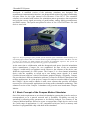
3 Concept of the ETH-ParaCare FES Systems............................................ 42
4 PC Based Rapid Prototyping FES System ............................................... 47
4.1 Hardware ........................................................................................................... 49
4.1.1 Electrical Stimulation Device.................................................................... 49
4.1.2 Digital Circuit Board ................................................................................. 49
4.1.3 Stimulation Amplitude and Stimulation Pulse Control Signals ................ 50
4.1.4 Power Supply............................................................................................. 50
4.1.5 Analog Circuit Board................................................................................. 51
4.1.6 Asynchronous Communication between Stimulation Device and PC ...... 52
4.1.7 Multi Function Board ................................................................................ 53
4.2 Assembler Software of the Stimulator ............................................................ 53
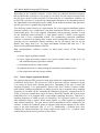
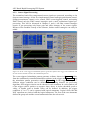
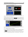
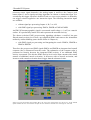
4.3 LabVIEW Software .......................................................................................... 54
4.3.1 Sensor Signal Acquisition Module ............................................................ 56
4.3.2 Sensor Signal Processing........................................................................... 57
4.3.3 Stimulation Parameter Setup Module........................................................ 59
4.3.4 Compensation of the Stimulation Recruitment Curves ............................. 60
4.3.5 Data Acquisition and Data Storage Routines ............................................ 61
5 Portable FES System ................................................................................. 62
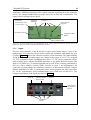
5.1 Basic Concept of the Compex Motion Stimulator.......................................... 63
5.2 Compex Motion Hardware............................................................................... 64
5.2.1 Inputs ......................................................................................................... 65
5.2.2 Stimulation Outputs................................................................................... 66
5.3 Compex Motion Controller Program (Firmware) ......................................... 68
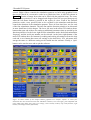
5.4 Compex Motion Programming Software........................................................ 68
5.4.1 Stimulation Modes and Frequency ............................................................ 70
5.4.2 Stimulation Sequence ................................................................................ 70
5.4.3 Stimulation Primitives ............................................................................... 71
5.4.4 Settings for Human Interaction Primitives ................................................ 75
5.4.5 Analog Control .......................................................................................... 79
5.4.6 Chip Card Download - Upload.................................................................. 81
6 EMG Signals: Features, Signal Acquisition, Stimulation Artifact
Removal ...................................................................................................... 82
6.1 Characteristics of SEMG.................................................................................. 83
6.1.1 SEMG Randomness................................................................................... 83
6.1.2 SEMG Stationarity..................................................................................... 84
11
6.2 SEMG Recording Techniques.......................................................................... 85
6.2.1 Electrodes .................................................................................................. 85
6.2.2 Amplifiers.................................................................................................. 86
6.2.3 Specifications of the Used SEMG Amplifiers........................................... 87
6.2.4 Filtering ..................................................................................................... 88
6.2.5 Signal Processing....................................................................................... 88
6.3 Stimulation Artifact Removing Techniques ................................................... 89
6.3.1 Characteristics of Stimulation Artifacts in Measured SEMG.................... 90
6.3.2 Methods to Remove Stimulation Artifacts in SEMG Signals ................... 92
6.4 Moving Ensemble Averaging Stimulation Artifact Removal Algorithm..... 92
6.4.1 Algorithm................................................................................................... 93
6.4.2 Validation Experiment............................................................................... 93
6.4.3 Signal Processing....................................................................................... 97
6.4.4 Results ....................................................................................................... 97
6.4.5 Discussion and Conclusions .................................................................... 103
7 Neuroprosthesis for Grasping ................................................................ 105
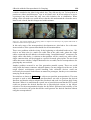
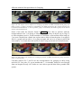
7.1 Components and Fixation .............................................................................. 105
7.2 Electrode Placement........................................................................................ 108
7.2.1 Electrode Positions for Finger Extension ................................................ 109
7.2.2 Electrode Positions for Finger Flexion .................................................... 110
7.2.3 Electrode Positions for Thumb Flexion/Opposition................................ 111
7.3 Control Strategies for FES Grasping ............................................................ 115
7.3.1 Push Button Control ................................................................................ 116
7.3.2 Voice Control .......................................................................................... 118
7.3.3 Digital SEMG Control............................................................................. 121
7.3.4 Sliding Potentiometer Control ................................................................. 123
7.3.5 Analog SEMG Control ............................................................................ 125
7.4 Advantages and Limiting Factors of EMG Control Strategies
Compared to Push Button and Potentiometer Control Strategies ............. 126
8 Results with the Neuroprosthesis for Grasping.................................... 127
9 Conclusions.............................................................................................. 132
Bibliography.................................................................................................. 136
Abbreviations
Medical Abbreviations:
ADL
AP
ASIA
CNS
EMG
FES
MD
OT
PT
SA
SCI
SEMG
Activities of daily living
Action potential
American Spinal Injury Association
Central nervous system
Electromyographic
Functional electrical stimulation
Medical doctor
Occupational therapist
Physical therapist
Stimulation artifact
Spinal cord injured
Surface EMG
Technical Abbreviations:
ANN
ARV
BOSFET
field
CMRR
DMA
FFT
FIR
FSR
EPROM
GAL
GUI
PC
RAM
RMS
SPI
S/N
Artificial neural network
Average rectified mean value
Bidirectional Metal-Oxide-Semiconductor
Effect transistor (MOSFET)
Common mode rejection ratio
Direct memory access
Fast fourier transform
Finite impulse response
Force sensitive resistor
Electrically programmable read only memory
Gate address logic
Graphical user interface
Personal computer
Random access memory
Root mean square
Synchronous serial port
Signal to noise ratio
12
1 Introduction
1.1 Background
The development of new rehabilitation technology like neuroprostheses has been more
the field of activity of universities and small spin-off companies than of globally
operating companies. The main challenges in this field lie more in the breadth of the
different medical aspects that are not clearly described or sometime even in a
contradictory manner than in the depth of finding an exact solution to a well described
phenomenon as in other engineering disciplines. Rehabilitation engineering requires the
interdisciplinary collaboration of medical doctors, therapists and engineers and all of
them have to be aware of the uncertainties and limitations of their techniques.
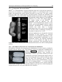
In medical fields like diagnostic and intensive care technology plays a dominant role.
One has realized, how the huge investments and efforts into diagnostic systems like
MRI scanners, X-ray and ultrasound equipment, and in patient monitoring systems
improved diagnosis, prognosis, and patient surveillance. As a result of these efforts it
was possible to tremendously shorten hospitalization time and more people could be
cured.
In contrast to the acute medicine rehabilitation therapy is dominated by manual
treatment methods mainly provided by therapists. Here, similar improvements can
potentially be expected from rehabilitation engineering that has its operating field on the
other side of the chain after the surgical intervention, the intensive care, and the acute
medicine. The main task of rehabilitation engineering is to help faster improve or/and
cure after the acute medical intervention by developing new technologies, concepts,
methodologies and assistive tools. In cases, where no complete cure can be expected
rehabilitation engineering can help to further assist and improve the conventional
therapy. Rehabilitation engineering deals with the human subject as an integral system
that is influenced by an unknown number of factors and combinations. It is faced with
the fact that exact knowledge about the human system and the ongoing processes during
rehabilitation are not completely understood and therefore make an engineering
approach rather difficult. Simple, fault tolerant and robust approaches have to be chosen
for practical, clinically applicable solutions. In the last few years the availability of
portable, battery powered high computational power in small size and miniaturized
sensor systems made the application of modern technology for assistive devices for
rehabilitation much more feasible.
13
1 Introduction
14
One of the cutting edge fields in rehabilitation engineering is the field of
neuroprosthetics, as it combines almost perfectly the artificial world of electronics with
the human 'circuits' called pathways with the aim to improve lost or pathological
functions. The field of neuroprosthetics, which has been existing for more than 40 years,
experienced a renaissance in the last decade. The main concepts that were invented by
the founders of the field Liberson, Vodovnik or in case of neuroprostheses for grasping
by Long and Masciarelli (Liberson et al., 1961, Long et al., 1963, Vodovnik et al., 1967,
Vodovnik et al., 1965) were brought to a clinical applicable commercial level by people
like Peckham, Nathan and Prochazka (Ijezerman et al., 1996, Peckham, 2001, Peckham
et al., 1992, Peckham et al., 1996, Prochazka et al., 1997).
Neuroprostheses for grasping are artificial systems that in a broad sense bridge
interrupted or damaged neural connections between the brain and upper extremity
muscles using a technique called Functional Electrical Stimulation (FES). Unlike the
name suggests, state of the art neuroprostheses are not even approximately able to
replace the neural structure and function of nerves, nerve bundles, the damaged part of
the spinal cord in case of Spinal Cord Injury (SCI), or a lesioned part of the brain e.g. in
stroke subjects. As a matter of fact neuroprostheses for grasping require intact motor
neurons that connect the spinal cord with the upper extremity muscles. A motor neuron
is a peripheral efferent nerve, a pathway from the central nervous system to the muscle.
Neuroprostheses bridge central lesions either of the spinal cord or the brain by detecting,
interpreting and commanding a desired motor action, which results in a limb movement.
For the detection of the desired actions man-machine interfaces and sensor systems are
used. The interpretation is performed by a microcontroller unit using a control scheme
and the motor action is commanded using FES.
In some publications FES is also referred to as Functional Neuromuscular Stimulation
(FNS) or Neuromuscular Electrical Stimulation (NMES). All three expressions refer to
the same method: the artificial generation of action potentials (APs) in peripheral
efferent nerves with the goal to produce muscle contraction. Therefore, short electrical
current pulses depolarize the motor neuron and generate nerve APs. The nerve APs
propagate along the motor neuron, branch, and are transmitted to the motor units that
articulate the limb by muscular contraction. The pulses are provided to specifically
selected muscles or muscle groups through electrodes that are placed close to the motor
neurons of the selected muscles. The electrodes must be placed in number and location
such that they produce useful synergic muscle contraction patterns for the intended limb
function.
1.2 State of the Art of Neuroprostheses
Only a few neuroprostheses that restore or improve the grasp function in SCI and stroke
subjects are commercially available and/or clinically used. They can be divided into two
main categories: implanted systems and non-invasive systems. Both categories have
their own advantages and disadvantages. Presently, two systems are commercially
available in Europe and USA: 1) the Freehand system from Neurocontrol Inc. (Keith et
al., 1988, Smith et al., 1987), an implantable FES system, and 2) the Handmaster from
Ness Inc. (Ijezerman et al., 1996), a system using transcutaneous (surface) stimulation
electrodes. A third system, the FESMate system from NEC Inc. (Takahashi et al., 1999),
1 Introduction
15
also an implantable system, is used for both upper and lower extremities. It is applied in
Japan, Korea and Taiwan, mainly in research. Other clinically used neuroprostheses for
grasping are the Bionic Glove from the University of Alberta (Prochazka et al., 1997),
whose commercialization failed in a first step, the Belgrade FES system (Fisekovic et
al., 2001), and the ETHZ-ParaCare neuroprostheses for grasping from ETH Zurich and
University Hospital Balgrist Zurich (Keller et al., 1998, Keller et al., 1999, Popovic et
al., 2001) presented in this thesis, of which the Compex Motion system is in the
commercialization process. In addition to the above mentioned neuroprostheses many
other FES systems were proposed that improve the grasp function (Haugland et al.,
1999, Lickel, 1998, Rakos et al., 1999, Saxena et al., 1995, Thorsen, 1998), but they
have not been commercialized or widely applied clinically.
1.3 Motivation, Aim and Contribution
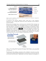
The motivation to develop the ETHZ-ParaCare neuroprostheses and Compex Motion
was driven by three main factors: 1) the lack of a flexible commercially available
neuroprosthesis for surface FES; 2) the observed need of a very flexible FES system,
especially, if used in an early phase of rehabilitation; and 3) the expressed interest and
need for such a system by the medical and therapeutic staff of the rehabilitation center
ParaCare, which agreed with the needs expressed by the FES community at FES related
conferences.
Several development steps were required to reach the goal of a flexibly programmable,
portable neuroprosthesis that is able to improve the grasp function in SCI subjects and
that is accepted by clinicians and users. In a first phase the feasibility of applying
neuroprostheses for grasping using surface stimulation electrodes to improve the grasp
function in SCI subjects in an early phase of rehabilitation was demonstrated. This
thesis is focussed on resolving a number of scientific, engineering and clinical questions
which stand in the way of commercially available “attach-and-go” devices that require
minimal training, adaptation and maintenance. Specifically, the most important research
goals of this thesis project were:
1. The development of a hardware platform (FES system) that can facilitate fast
testing of concepts and methods based on FES for the restoration of the grasp
function in SCI subjects. This platform was used to develop control strategies
that are suitable for controlling the neuroprostheses. Two successfully
functioning prototypes of neuroprostheses for grasping were developed: A
stationary rapid prototyping and a portable FES system. Experiments with SCI
subjects, conducted in our laboratory, demonstrated that the neuroprostheses for
grasping could significantly improve the grasp function in SCI subjects.
2. The development of control strategies that command the neuroprostheses for
grasping to perform different types of grasps. One of the main focus was on
exploring control strategies that use electromyographic (EMG) signals from
voluntarily activated muscles during FES to command the grasp task.
3. The development of new programming and controller (firmware) software
programs for an existing, commercially available stimulator 'Compex 2'. The
new software concept elevated the stimulator with the brand name 'Compex
1 Introduction
16
Motion' to a new dimension of applications in basic and applied research in
terms of flexibility, versatility and applicability. The new concept and features
enabled us to build new portable neuroprostheses for grasping based on the
commercially available stimulator.
4. The performance of first clinical trials and ‘in-field’ tests with the portable
neuroprosthesis for grasping.
The main contribution of the thesis are new concepts, the implementation and testing of
flexibly programmable neuroprostheses as a therapeutic tool or a permanent aid for
improving the grasp function in SCI subjects using surface FES technology. Therefore, a
stationary rapid prototyping and a flexibly programmable portable FES system, five
different control strategies, and a new algorithm for the real-time removal of stimulation
artifacts in recorded EMG signals from voluntarily contracted muscles were developed.
All concepts were successfully tested in a clinical environment. Resulting from this
work a new generation of versatile, portable stimulators - Compex Motion - are on the
way toward commercialization, which will bring to neuroprostheses unprecedented
flexibility of the stimulation patterns and sequences, the man-machine interfaces, and
the control strategies. This high flexibility combined with a fast and intuitive graphical
'drag and drop' programming technique makes the neuroprosthesis for grasping
applicable in an early rehabilitation phase, where changes of the subject's neurological
condition are always present and demand an adjustment of the neuroprosthesis
parameters, the number of the stimulated muscles, and the stimulationelectrode
positions.
1.4 Structure of the Thesis
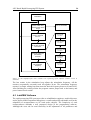
The thesis is structured into nine chapters. The second chapter provides basic
information about the physiological processes involved in muscle contraction using FES
and describes the influence of the stimulation parameters: pulse width, pulse amplitude,
pulse shape, and stimulation frequency. It presents the concepts of the different currently
used stimulation electrodes and their influence on muscle selectivity, which is an
important factor in neuroprostheses for upper extremities. A subchapter briefly describes
the tetraplegic subject, focussing on the functional deficits in the upper extremities,
since he/she is not only the customer of the system, but also a part of it. At the end of
the chapter an overview of the currently existing and used neuroprostheses for grasping
divided in implanted and surface FES systems is given.
The third chapter describes the concept of the ETHZ-ParaCare FES systems and of the
Compex Motion stimulator. It points out the requirements for a modern and flexible
stimulator needed for neuroprosthetic applications.
The fourth chapter presents with the stationary rapid prototyping FES system. This
system is mainly used to develop new control strategies, stimulation patterns and
general concepts, of which the successful concepts are implemented in the portable
system. The chapter describes the stimulation hardware and the LabVIEW programmed
FES controllers and the recording software that runs on a PC.
The fifth chapter briefly describes the ETHZ-ParaCare portable FES system, which was
used as a demonstrator of a flexible neuroprosthesis for grasping and was used with
1 Introduction
17
some of the subjects in activities of daily living (ADL) before the Compex Motion
system was completed. Six such portable FES systems were built. They were very useful
for testing and showing our concepts and convincing our industrial partner Compex SA
to start a collaboration with the goal to enhance their stimulator Compex 2 to be able to
perform the functions needed for neuroprosthetic applications. The main part of the
chapter describes the Compex Motion concept, the hardware, the firmware, and the
stimulator programming software.
The sixth chapter first addresses the main characteristics of recorded surface
electromyographic (SEMG) signals from voluntarily activated muscles, the
measurement hardware, the filtering techniques, and our processing algorithms of the
SEMG. The next part of the chapter describes the proposed techniques used to eliminate
stimulation artifacts (SAs), which are always present in the SEMG signal of a muscle
close to stimulated muscles and must be removed. The last part of the chapter describes
a novel technique that is capable of eliminating in real-time the major part of the slowly
decaying SA tail, which is the main disturbance of the SEMG signal recorded close to a
stimulation site. In control strategies using SEMG signals the presented SA removal
algorithm can be successfully applied.
The seventh chapter describes the developed neuroprostheses for grasping. First, the
components, the cabling and the fixation of the systems on the subjects' electrical
wheelchairs are presented. The second subchapter explains the electrode positions,
specifies the expected muscle contractions and the resulting limb functions. Another
subchapter describes in detail the control strategies, the stimulator setups, and the
stimulation patterns used with the Compex Motion portable FES systems. At the end of
the chapter advantages and limiting factors of EMG control strategies are discussed and
compared with the other control strategies.
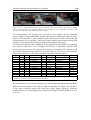
In the eight chapter the main results obtained with the neuroprostheses for grasping in
our clinical trials are summarized. The main emphasis here is put on explaining our
rehabilitation procedure. Unfortunately, the functional outcome could not be assessed
consistently, because the systems were always in a development phase and the
functional outcome depended much on the actual development state. It will be the task
of a multicenter trial performed with the Compex Motion system in the near future to
assess the functional outcome in activities of daily living (ADL) and to show the
applicability of the Compex Motion neuroprosthesis for grasping in early rehabilitation
for restoring and/or improving the hand function in SCI and stroke subjects. Our results
provide strong promise of a successful application.
The ninth chapter, the conclusion, gives a brief summery of the developed FES systems,
their performance and limitations, and provides an outlook for future enhancements.
1.5 Acknowledgements
The work presented in the thesis was supported by grants from the Swiss National
Science Foundation, Switzerland (SPP Biotechnology, Project No. 5002-044895)
and
the Federal Commission for Technology and Innovation, Switzerland (Project
No. 4891.1)
2 Principle and Function of Neuroprostheses for
Grasping
This introductory chapter provides basic information about:
•
the physiological processes involved in the generation of action potentials, how
they propagate through the nerve fibers, and how muscle contraction is caused.
•
how muscles are artificially activated by electrical stimulation.
•
the influence of the different stimulation parameters: pulse width, pulse
amplitude, pulse shape, and stimulation frequency.
•
the concepts of the different currently used stimulation electrodes and their
influence on muscle selectivity, stimulation comfort, and applicability for
neuroprostheses for grasping.
•
the tetraplegic subject, focussing on the functional deficits in the upper
extremities.
•
the currently existing and used implantable and surface neuroprostheses for
grasping.
Neuroprostheses based on FES are systems that artificially generate muscle contractions
obeying commands of the user. A neuroprosthesis combines artificial parts (electrical
stimulator, wires and electrodes) and natural parts (nerves and muscles) of the human
body with the function to overcome a neuronal lesion in the central nervous system
(CNS). The lesion can be in the spinal cord (Spinal Cord Injury) or in the brain (e.g.
stroke). It is obvious that the natural parts of the body significantly influence the
function of the neuroprosthesis. This first chapter gives a brief overview of the involved
parts and provides some information about the most important currently available
neuroprostheses.
2.1 Muscle and Nerve Properties and Activation Mechanisms
during Functional Electrical Stimulation (FES)
In this subsection the basic nerve and muscle properties will be addressed. More
information about nerve properties can be found in (Guyton et al., 1996). Muscle
function and properties are described in detail in (Karu, 1992, Silbernagel et al., 1991).
More clinically relevant aspects of FES are discussed in (Baker et al., 1993, Popovic et
18
2 Principle and Function of Neuroprostheses for Grasping
19
al., 2000). The last reference gives also detailed information about what is achievable in
the prosthetic field.
2.1.1 Generation of Action Potentials
The basic principle to contract a muscle using FES is to artificially generate action
potentials in efferent muscle nerve fibers called motor neurons. Efferent nerve fibers
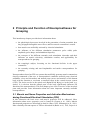
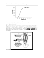
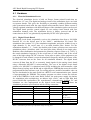
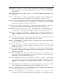
(see Figure 1) are the descending axons from the brain to the muscles, whereas the
afferent nerves are the ascending axons that provide the sensory information to the CNS.
Figure 1: The motor neuron. Reprinted from (Karu, 1992).
An action potential (AP) can be generated by depolarizing the nerve. In normal steady
state conditions there is a difference of the electrical potential between the inside and the
outside of the nerve membrane of 70 - 90 mV. The potential inside the nerve membrane
is electrically negative with respect to the outside potential. This difference is due to a
high concentration of cellular anions and a poor concentration of sodium (Na+) ions
inside the nerve membrane. In the resting state the concentration of potassium (K+) ions
inside the nerve is higher than outside. However, the cell membrane in osmotic
equilibrium keeps more cellular anions inside the nerve than cations. Furthermore, the
membrane is more permeable to potassium than to sodium and other cations. In
equilibrium the resting potential inside the membrane is at about -80 mV with respect to
the outside of the nerve cell. An AP can be characterized as a short depolarization of a
nerve fiber with a duration of approximately 400 µs. During that time the inside nerve
potential changes from -80 to +40 mV, as a result of fast opening of sodium selective
channels and the inflow of sodium ions driven by the large sodium concentration
outside the nerve and the voltage gradient. Shortly after the sodium inflow potassium
channels open, potassium ions flow out and a repolarization takes place. In a third phase
the osmotic pressure reestablishes the ionic concentrations of the resting condition (see
Figure 2).
2 Principle and Function of Neuroprostheses for Grasping
20
Figure 2: Electrical nerve properties during an action potential. Reprinted from (Silbernagel et al.,
1991).
An AP can be triggered by an electrical stimulus that is applied to the excitable tissue of
a nerve fiber with a pair of stimulation electrodes. A short current pulse depolarizes the
muscle nerve fibers close to the cathode (-). The current pulse induces a flow of positive
ions from the anode (+) to the cathode (-) and a flow of negative ions in opposite
direction. The positive charge is absorbed at the cathode. Close to the cathode the
positive potential outside the nerve membrane with respect to the potential inside the
cell is decreased. In other words the nerve fiber inside the membrane has a less negative
potential. As a consequence, voltage gated sodium ion membrane channels are triggered
to open.
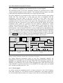
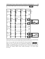
The function of the voltage gated sodium ion membrane channels can be described
using a model with two sodium channel gates, a fast sodium channel activation gate m
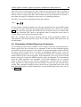
and slow sodium inactivation gate h (Grill et al., 1995) (see Figure 3). In reality the
opening and closing of the sodium membrane channels are not driven by gates but by
conformation changes in the membrane-spanning domains of the channel proteins that
2 Principle and Function of Neuroprostheses for Grasping
21
form the sodium channel (Guy et al., 1986). In resting state the activation gate is almost
completely closed and the inactivation gate is about 75 % open. Changes of the
electrical potential inside the nerve with respect to the outside influence the membrane
spanning of the sodium channel protein. A depolarizing pulse (negative current pulse)
opens the activation gate m and at the same time starts closing the inactivation gate h as
shown in Figure 3. The time constant of the activation gate τm is 100 times faster than
the time constant of the inactivation gate τh . Therefore, during the time gate m is open
and gate h is not fully closed, sodium ions driven by the concentration gradient flow
through the channel inside the nerve and depolarize the nerve rapidly. Once the
inactivation gate h is closed, the sodium influx is stopped. The re-polarization process of
the nerve starts taking place. It is driven by the osmotic pressure that causes an efflux of
cations through non-specific leakage channels. After ~600 µs the resting condition of
about -80 mV is established. Through this process the gate m is closed and h is opened
and ready for another AP.
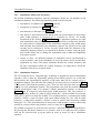
A
stim
1
B
h
0.5
Membrane gates:
m
0
h
C
0
m
-40
membrane
transmembrane potential
-80
0
500
1000
1500
time [µs]
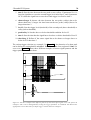
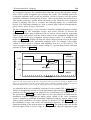
Figure 3: A simplified model uses an activation gate m and an inactivation gate h to describe the
behavior of voltage driven sodium channels that play a major role in the process of generating APs. The
Figure shows A) the stimulus, B) the conditions of the two gates h and m, and C) the transmembrane
potential as a function of time during a depolarizing stimulus that generates an AP. Adapted from (Grill
et al., 1995).
Hyperpolarization of the nerve (generated by reversing the stimulation current) can also
produce an AP known as anodic break excitation. During long time hyperpolarization
(500 µs or longer) with positive current pulses the fast activation gate m closes a bit
more and the inactivation gate h opens fully (in resting position it is only 75 % open). At
the end of the stimulation pulse the activation gate m opens a bit and because the
inactivation gate is fully open an influx of sodium ions can initiate an AP, if the
activation gate opens sufficiently.
2 Principle and Function of Neuroprostheses for Grasping
22
2.1.2 Propagation of Action Potentials
The local influx of sodium ions and the polarization of the nerve affects the neighboring
sodium channels to operate in the same manner, with a slight time delay. This results in
a propagation of the AP. The AP propagates along the nerve with a propagation velocity
of about 30-120 m/s, depending on the nerve type, and reaches the axon terminal where
the neurotransmitter acetylcholine is released. This neurotransmitter diffuses into the
synaptic gap and is absorbed by the so called motor end plate receptors. They are located
on the muscle membrane. The received acetylcholine causes a depolarization of the
muscle membrane and initiates a contractile muscle twitch.
2.1.3 Excitability of Nerve Fibers
The excitability of nerve fibers depends on the following factors:
•
the distance of the excitatory electrode (cathode) to the nerve
•
the diameter of the nerve fiber
•
the applied electrical charge
The closer a stimulation electrode is positioned to a nerve the lower the stimulation
intensity can be chosen to excite it. Additional tissue between the electrode and the
nerve reduces the voltage gradient between them. The excitability of nerve fibers
changes also with the change of the fiber diameter. The larger the nerve fiber is in
diameter the easier the nerve can be electrically excited. This effect is reported in
literature as reverse recruitment order (Blair et al., 1933). Natural voluntary contraction
with a relatively weak force, e.g. a well controlled precision grasp, mainly involves
fatigue resistant type I muscle fibers that are innervated by motorneurons with a small
diameter. The large, fast nerve fibers that are easier to excite by FES, innervate type II
muscle fibers. Those muscles have a fast, high twitching force, but are fast fatiguing.
For normal grasp tasks type I muscle fibers are used and on demand for faster reaction
or a higher force type II fibers are recruited. In FES with lower stimulation intensity first
large nerve fibers connected to type II muscles are recruited and only with an increased
stimulus also small nerve fibers connected to type I muscle fibers start being recruited.
The question how a nerve has to be stimulated to obtain the best response can be
answered as follows. The stimulus signal has the task to provoke a depolarization of the
nerve in order to excite an AP. The osmotic pressure balances the voltage inside the
nerve fiber to about -80 mV, therefore the artificial depolarization of the nerve has to be
faster than the re-polarization maintained by the membrane charge pumps. This
demands a sharp slope of the stimulation current. In order to provide a fast
depolarization good stimulators have stimulation current slopes greater than 5 ⋅ 10 4 A/s.
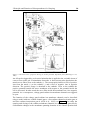
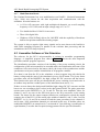
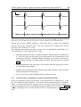
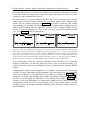
In practice the excitability of the nerve is measured by recording the motor thresholds
(the weakest stimulus that provokes a muscle response) for different stimulus pulse
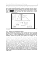
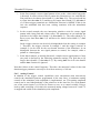
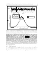
duration and intensities. The result is plotted in a so called intensity-duration curve.
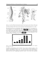
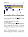
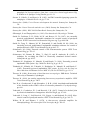
Such a curve shows the shortest pulse duration for a given stimulus intensity that
provokes a motor response. Figure 4 shows intensity-duration curves of innervated and
denervated muscles. Typically, for innervated muscles a pulse width longer than 300 µs
does not produce much more muscle contraction for a given stimulation intensity (e.g.
2 Principle and Function of Neuroprostheses for Grasping
23
40 mA) and a pulse width shorter than 50 µs needs a very high stimulus intensity to
reach motor threshold. The motor threshold is the level of the weakest muscle response
to a stimulus. Similarly, for denervated muscles a non-linear intensity-duration behavior
can be observed, but the required pulse duration has to be more than 100 times longer.
140
120
current [mA]
100
innervated
muscle
motor
threshold
innervated muscle
near maximum
motor response
denervated muscle
motor threshold
80
60
40
20
0
0.01
0.1 0.3
1
10
100
1000
pulse width [ms]
Figure 4: Curves of equal motor response for different pulse widths and pulse amplitudes. For intact
motorneurons stimulation pulses longer than 300 µs do not increase the motor response if the stimulation
amplitudes are higher than 40 mA. Denervated muscles require a 100 - 1000 times longer stimulation
pulse width than innervated muscles (Data from wrist extensor, surface stimulation, stimulation
frequency 35 Hz). Adapted from (Baker et al., 1993).
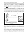
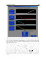
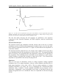
Between the motor threshold and the near maximum motor response the increase of the
stimulus intensity excites more and more nerve fibers that generate more and more
muscle force. The stimulus-force or stimulus-torque relationship is depicted in so-called
recruitment curves. They show the static non-linearity of the force output of an
electrically excited nerve-muscular system. Figure 5 shows the recruitment curve of a
quadriceps muscle for isometric contraction. The system dynamics also behave nonlinearly. The non-linear static and dynamic properties of the nerve-muscular system
have been described (Dorgan et al., 1997, Hill et al., 1975, Huxley, 1957, Riener et al.,
1996) and reviewed (Winters et al., 1990, Zahalak, 1992, Zajac, 1989) by many authors
using several different models.
2 Principle and Function of Neuroprostheses for Grasping
24
Figure 5: Curves that show the static stimulus intensity-force relation are called recruitment curves. The
data was obtained from a quadriceps femoris with surface electrodes, pulse duration 100 µs, and a
frequency of 35 Hz. Reprinted from (Baker et al., 1993).
2.1.4 Muscle Contraction
The detailed mechanisms that cause muscle contraction are described in (Karu, 1992) or
(Silbernagel et al., 1991). Only a brief summery of the most important processes is
given here. A muscle consists of about 100 - 2000 motor units and the number of
muscle fibers in a motor unit amounts to 5 - 1000 (see Figure 6 and Figure 7). Each
muscle fiber again consists of a bundle of myofibrils that are incased by the
sarcolemma.
SARCOMERE
Figure 6: Morphology of skeletal muscle. Reprinted from (Baker et al., 1993).
2 Principle and Function of Neuroprostheses for Grasping
25
The motor nerve axon terminal is connected to the motor unit at the neuromuscular
junction, called motor end plate. It is located at the muscle fiber's midpoint, causing a
symmetric muscle fiber contraction in both directions. Whenever a nerve AP reaches the
motor endplate acetylcholine is released over a small gap called synaptic cleft and
generates a muscle AP. This process lasts about 6 ms. The muscle AP propagates along
the muscle fiber in both directions and is transported through the transverse
tubulesarcoplamic reticulum system (T-tubules) to the myofibrils (see Figure 7). In a
myofibril there are about 1500 actin and 3000 myosin filaments (large polymerized
proteins), which form the contractile muscle structure. The actin filaments are held in Zdiscs around the myosin filaments as shown in Figure 7. The myosin heads arranged
with a joint like connection around the myosin filament adhere to the actin filament. A
repetitive angular conformation change of the myosin heads combined with a
docking/undocking process to the actin takes place in the following order: 1) docking
the myosin head to actin filament, 2) changing the angle from 90 to 50° (Figure 7 C), 3)
undocking, and 4) returning to 90° makes the myosin slide inside the actin filaments
what causes muscle contraction. The underlying chemical processes are described in
(Silbernagel et al., 1991).
A. Structure of fasciated muscle fibers
B. Structure of a sarcomere
C. Myosin molecule
Figure 7: Sarcomere anatomy. Reprinted from (Silbernagel et al., 1991).
2 Principle and Function of Neuroprostheses for Grasping
26
Each cycle causes a contraction of 1% of the muscle length. A muscle can contract
about 50% of its initial length. It can perform the full contraction in 100 - 200 ms.
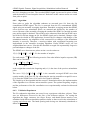
It was pointed out before that the muscle dynamics are non-linear. One of the reasons is
the non-linear maximal isometric contraction force for different sarcomere lengths as
shown in Figure 8. The skeletal muscle has its optimal operating point at a sarcomere
length of about 2 - 2.2 µm. For example, the optimal operating point of the finger
flexors is at 30° wrist extension.
Figure 8: Maximal isometric contraction force of skeletal and heart muscles. Reprinted from (Silbernagel
et al., 1991).
2.1.5 Influence of the Stimulation Frequency
A single stimulation pulse generates an AP that propagates along the nerve and results
in a muscle twitch. A single muscle twitch lasts only about 100 - 200 ms. By applying
trains of pulses (3 - 10 Hz) the stimulated muscles experience tremor. Increasing the
stimulation frequency puts the single muscle twitches closer together, they start
overlapping to the extreme that the muscle is not able to relax anymore. This continuous
muscle contraction is called tetanization. For stimulation frequencies above 25 Hz the
tremor becomes very small and tetanic contraction is obtained. Increasing the
stimulation frequency smoothens the tetanic contraction further, but has the
disadvantage of increasing muscle fatigue. During physiological contractions the muscle
fibers are activated randomly through thousands of nerve fibers. The APs are fired
asynchronously with a firing rate between 0.3 - 5 Hz depending on the desired force and
the fatigue level of the muscle. This asynchronous firing results in tetanic contraction
although the stimulation frequency for a single motor unit is low, whereas in artificially
stimulated nerves the AP's are generated all at the same time. The spatio-temporal
distribution of AP's as it is produced during natural contractions can not be generated
artificially with FES. For tetanic contractions the muscle has to be stimulated with a
rather high stimulation frequency around 20 Hz or higher. The high stimulation
frequency reduces the recovery time of the muscle fibers and produces a faster fatiguing
of the muscles.
2 Principle and Function of Neuroprostheses for Grasping
27
Besides increased muscle fatigue there is also another limit to increasing the stimulation
frequency for muscle activation. With stimulation pulses at frequencies above 600 Hz
muscle contraction can be hindered. Studies from Baratta et al. (Baratta et al., 1989)
showed that by applying a high frequency stimulation train of 600 Hz or higher using a
nerve cuff electrode distal to an electrode with normal 20 - 50 Hz stimulation pulses one
can selectively prevent the muscle from contracting. With a higher amplitude of the high
frequency pulses muscles innervated with slower nerves (smaller diameter) are
prevented from contraction. With a low amplitude of the high frequency pulses mostly
fast nerve fibers (big diameter) are blocked hindering contraction of fast muscles. The
authors suggested this method to be applicable against the reversed recruitment order of
artificially stimulated muscles. Although the phenomenon is not completely understood
some literature provides support to the notation that high frequency stimulation
maintains the endplates in a temporary refractory state preventing the muscle from
contracting (Solomonow, 1984).
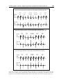
2.1.6 Waveform of Stimulation Pulses
The waveform of the current pulse plays a significant role in the daily application of
FES. APs should be generated by sharp edged negative current pulses with a pulse
duration of at least 40 µs (see intensity-pulse duration curve in Figure 4). Shorter pulses
or pulse slopes less than 10 4 A/s need a largely increased current to generate an AP.
Stimulation pulses longer than 300 µs applied with surface electrodes only recruit a few
more nerve fibers, but generate more pain since they stimulate preferably afferent nerves
that are sensitive to a longer pulse duration. If such sharp edged negative monophasic
current pulses are applied over a long period of time the unidirectional ion current flow
has the potential for ion accumulation and skin irritation. Therefore, biphasic
stimulation pulses that remove the induced electric charge are used for FES
applications. In practical applications either symmetric or asymmetric biphasic
stimulation pulses are used. Asymmetric stimulation pulses are produced such that an
AP is only generated under one of the two stimulation electrodes, whereas symmetric
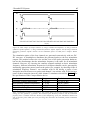
biphasic pulses generate APs under both stimulation electrodes. Figure 9 shows the
most commonly used pulse forms.
2 Principle and Function of Neuroprostheses for Grasping
28
a)
b)
c)
d)
Figure 9: Commonly used pulse forms. The depolarization pulse is for all pulse forms rectangular with a
pulse duration up to 300 µs and the hyperpolarization pulse is a) not existent = monophasic pulse; b) the
same as depolarization pulse = symmetric biphasic pulse; c) longer than the depolarization pulse, with a
sub-threshold amplitude = asymmetric rectangular biphasic pulse; or d) shorter than the depolarization
pulse, with a sub-threshold pulse duration = asymmetric exponentially decreasing biphasic pulse
All biphasic pulse forms have in common that the charge is balanced. The main
difference between symmetric and asymmetric pulses is that the hyperpolarization pulse
(positive pulse) of the asymmetric pulse has either a small amplitude (Figure 9c)) or a
small pulse duration (Figure 9d)) such that the stimulation intensity under the charge
balancing electrode (also called indifferent electrode) is below motor-threshold.
Asymmetric biphasic pulses are preferably used for the activation of small muscles, e.g.
for finger flexion/extension, if a greater muscle selectivity is needed. If the electrode
pair can be placed on the same muscle, e.g. on the quadriceps muscles, more force can
be generated with symmetric biphasic pulses.
2.1.7 Current or Voltage Regulated Stimulation
For FES two different types of neurostimulators are used: voltage regulated and current
regulated stimulators. The excitation of an AP with a voltage regulated stimulator
depends very much on the impedance of the underlying tissue. Muscle contraction is
much weaker if the voltage loss between the electrode and the tissue is higher. A change
of the impedance occurring from dried out skin under the surface electrodes affects
strongly the muscle response. Current regulated stimulators with their very high output
impedance are more stable and independent of large impedance changes. They provide a
better control of the muscle contraction than voltage regulated stimulators, because they
compensate electrode-tissue impedance changes. On the other hand, if the electrodetissue impedance becomes partially very high, a high current density can cause skin
irritation or even skin burns under the part of the electrode with the lower impedance. In
this case and in the case of an electrode failure the current regulator increases the
2 Principle and Function of Neuroprostheses for Grasping
29
stimulation voltage up to its limit. Stimulation voltages of several hundred volts can be
produced.
2.1.8 Stimulation of Denervated Muscles
If a motor neuron looses the connection to the spinal cord due to a peripheral lesion the
nerve degenerates over time and leaves the muscle denervated. In principle, it is also
possible to stimulate denervated muscle by directly stimulating the motor endplate. In
such a case the needed currents to generate muscle contraction are much higher than for
innervated muscles (see Figure 4). In practical applications with surface stimulation
electrodes a long pulse duration of 200 - 300 ms must be applied. With such a long
pulse duration a relatively moderate current (about 20 mA) can be chosen. But because
of the long pulse duration only 2 to 3 pulses/s can be generated per stimulation channel.
A tetanic muscle contraction can only be achieved on big muscles with multiple
stimulation channels using the carrousel method (alternating change of the stimulated
location on a muscle using multiple electrodes). Alternatively, with shorter pulse
duration and high currents of several hundred mA tetanic contraction can be achieved.
In this case special care has to be taken that the current densities on the skin do not
become too high. One has to use big electrodes with good contact to the skin. For
chronic treatment FES of denervated muscles can not be recommended, because in
contrast to spastic muscles a trained denervated muscles immediately atrophy, if the
intensive muscle training is interrupted.
Nevertheless, the Vienna FES group chronically trains in a special FES program
denervated lower limb muscles of SCI subjects (Kern et al., 1999). They could show
that denervated and atrophied muscles recover after an intensive training of 9 months
and more. Such recovered atrophied muscles can be functionally stimulated (tetanized)
with pulses with 10 - 30 ms pulse width (Kern et al., 2001). Subjects participating in
this program report benefits for their cardiovascular system resulting in an improved
quality of life.
2.2 Stimulation Electrodes
2.2.1 Cuff Electrodes
Cuff electrodes are wrapped around the nerve bundle where they stimulate the nerve at
the closest possible position. The cuffs are made of stainless steel or other conductive
bio-compatible material. Two or more cuffs are
molded in a silastic tube that provides a stable
distance and diameter of the cuffs to the nerves
and therefore provides well defined and stable
electrical properties. Basic models exist for
bipolar or tripolar electrode configurations, newer
models can have 12 or more channels. Because
the nerve bundles consist of many motorneurons
that lead to different muscle groups cuff
electrodes have a poor muscle selectivity.
Brindley et al. (Brindley et al., 1986) developed tripolar cuff electrodes for sacral
anterior root stimulation that have been successfully implanted in several hundred
2 Principle and Function of Neuroprostheses for Grasping
30
subjects for bladder contraction and voiding. The Brindley electrodes are assembled like
a book with 4 sheets and wrapped around three roots per ramus. Although three
stimulation channels can be used per ramus, the muscle selectivity is rather poor.
Attempts to stimulate the lumbar anterior roots for walking (Donaldson et al., 1997,
Rushton et al., 1996) using Brindley electrodes failed due to poor muscle selectivity. For
the same reason cuff electrodes are not used for FES of upper extremities at this time.
With the design of new multichannel electrodes people try to overcome this problem by
only stimulating parts of the nerve bundle.
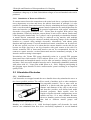
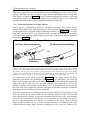
2.2.2 Percutaneous Intramuscular Electrodes
Recent percutaneous stimulation electrodes are made of multistrand fine filament
stainless steel wires and are coated with teflon. The wires are manufactured in a spiral
configuration and housed in a silastic tube to reduce
electrode breakage (Handa et al., 1989).
Percutaneous intramuscular electrodes are implanted
using a long hypodermic needle. The procedure can
be done minimal invasive. Thus percutaneous
electrodes can be implanted more easily than
epimysial electrodes (see below) that need an almost
uncovered target muscle for implantation.
Percutaneous electrodes are commonly used with
external systems, if a good muscle selectivity is
required. Especially the Sendai group and in the
1980s the Cleveland group used such percutaneous
electrodes for FES of upper extremities. A disadvantage of percutaneous electrodes is
the susceptibility to infection, migration problems and electrode breakage.
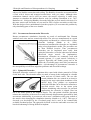
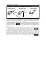
2.2.3 Epimysial Electrodes
Epimysial electrodes consist of a platinum disc coated with silastic material or Teflon
on the back side. The electrode cables are made of strong leads configured in a double
helix and cast in silastic tubes. The one side
Epimysial Elecrode
coated platinum discs are sutured in an invasive
surgery to the outer epimysium membrane of the
muscle body. They produce an asymmetric
electrical field that can be directed to stimulate a
specified muscle close to the motor point
without stimulating other muscles. In practical
applications the electrode is aligned close but
not at the motor point of the targeted muscle. The sub-optimal electrode placement
reduces the sensitivity of the nerves to small electrode displacements generated by limb
movements. Additionally, it prevents an “all-or-none” stimulation with a poor control of
the muscle when changing the stimulation intensity (Smith et al., 1987). This type of
electrode was developed by the Cleveland group and is used in the commercially
available Freehand system. The epimysial electrode is selective and stable over time, but
has the disadvantage of being difficult to implant.
2 Principle and Function of Neuroprostheses for Grasping
31
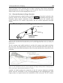
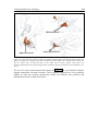
2.2.4 Transponder Electrodes BIONsTM
BIONTM is a microminiature electrical stimulator that can be injected into muscles or
near nerves. It consists of a cylindrical glass capsule of 2 mm diameter and 13 mm
length with hermetically sealed iridium electrodes on both ends. The glass capsule
houses an ASIC and a radio frequency coil that together constitute the stimulator. 256
such BIONsTM can be individually controlled with an external device using an eight bit
programmable unique address for each BIONTM
(Cameron et al., 1993). The control signal and
the supply voltage of the BIONsTM are
transmitted using an inductive coil. The
BIONsTM can be implanted into muscles or near
muscle nerves using minimal invasive surgery
techniques. The BIONsTM are injected with an
insertion tool made from a 12-gauge
angiocatheter that can be used to test stimulate
the location before permanently injecting the
electrodes (Cameron et al., 1997).
Preferred applications are therapeutic electrical
stimulation of deep muscles, e.g. electrical
stimulation to treat shoulder subluxation. At the
moment, neuroprosthetic applications are not
considered, because the required transmitter
power is at the moment too high for most
portable applications. Next generation devices
might have a more efficient power and transmission scheme to be able to build portable
systems.
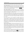
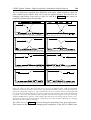
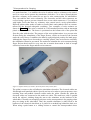
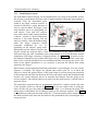
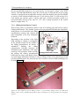
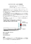
2.2.5 Self-Adhesive Electrodes for Transcutaneous Stimulation
Self-adhesive electrodes for transcutaneous stimulation use a gel to contact a conductive
member with the subject's skin. The electrode is built in a multi-layer configuration as
shown in Figure 10, consisting of two layers of
hydrogel. The skin interface layer includes an
electrically conductive gel with a relatively low peel
strength for removably contacting the subject's skin. It
has a wet feeling and can be removed relatively easily
from the skin. The conductive gel is made from
copolymers derived from polymerization of acrylic
acid and N-vinylpyrrolidone . A second hydrogel
layer connects the substrate (a low resistive material)
with the skin hydrogel layer. This second conductive gel layer has a relatively high peel
strength that provides very good adhesion to the substrate.
2 Principle and Function of Neuroprostheses for Grasping
32
Figure 10: Recent self-adhesive stimulation electrodes are manufactured in a multi-layer configuration.
Reprinted from (Axelgaard, 2001).
As material for the substrate conductive fabric, carbon film, or other conductive
materials are used. A wiring cable connects the electric stimulator to the self-adhesive
electrode substrate.
Between the two hydrogel layers a scrim layer can be introduced. This scrim layer can
be used to prevent slippage of the two hydrogel layers or it is used to strengthen the
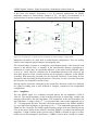
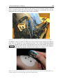
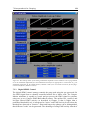
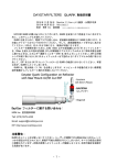
multi-layer substrate. A new type of self-adhesive electrodes, the Ultrastim® electrode,
uses a scrim layer to redistribute the stimulation current that it receives from a metal
connector pin on a garment (see Figure 11). Therefore the Ultrastim® electrode can be
positioned more freely on the garment. The second hydrogel layer delivers the
stimulation current obtained from the metal pin to a scrim layer made from a good
conductive carbon film. The scrim layer homogeneously redistributes the stimulation
current and provides it via a first self-adhesive hydrogel layer to the skin.
Figure 11: The specially designed electrode Ultrastim from Axelgaard Mfg. Co., Inc. can be placed
individually on the garment. It is connected to the stimulator with a connector pad. Reprinted from
(Axelgaard, 2001).
The main goal of the multilayer construction of the self-adhesive electrode is to provide
a balanced most equally distributed stimulation current density over the whole electrode
to prevent the skin from burns. Additionally, the electrode substrate-skin impedance is
2 Principle and Function of Neuroprostheses for Grasping
33
kept as low as possible to excite the least afferent nerves possible. The worldwide
leading producer and patent owner (Axelgaard et al., 2001) of self-adhesive electrodes is
Axelgaard Mfg. Co., Inc.
2.2.6 Other Electrodes for Transcutaneous Stimulation
Other electrodes for surface stimulation are metal plates covered with fabric tissue or
carbon electrodes. Both types are not self-adhesive and require water or special
electrode gel to equally distribute the electrical current over the electrode surface. The
wetted fabric tissue equally distributes the current over the entire metal plate in order to
prevent skin burns. With this type of electrode one has to be careful that the electrode
does not dry out. In the best case (if completely dry) such a dried out electrode isolates
the metal plate from the skin. But while drying out, unequally distributed electrical
fields under the electrodes may cause severe skin burns. Carbon electrodes are more
safe. The carbon rubber has a rather high electrical resistance that prevents high voltage
drops in different regions of the electrode and provides a better current distribution.
Additionally, the rubber always keeps the skin underneath the electrode a little bit
humid by the sweat. Carbon rubber electrodes and tissue covered metal electrodes are
fixed to the skin with elastic straps or built in a garment or brace as it is the case, for
example, with the Handmaster neuroprosthesis.
2.2.7 Discussion: Implanted Electrodes versus Surface Electrodes
In the beginning of the 1960s pioneers in the FES field like Liberson (Liberson et al.,
1961), who is regarded as the inventor of FES, and Long et al. (Long et al., 1963), who
proposed the first FES based system for grasping, used surface electrodes for the
stimulation of lower and upper extremities. Later, especially for upper limb FES
applications the demand for a higher muscle selectivity motivated people to start using
percutaneous intramuscular needle electrodes. They can be inserted very precisely to the
targeted muscles, even if the muscles are in deeper layers. Unfortunately, the danger of
electrode breakage and infection is always present with percutaneous electrodes, so FES
groups in different centers started to develop fully implantable systems. The electrodes
developed with such systems have the potential to be very selective, while the risk of
infection is reduced. Also the stimulation pulses do not have to pass through the skin,
where they can stimulate the skin receptors that provoke pain and unwanted reflexes.
Generally, stronger forces can be produced with implanted electrodes. Because the
electrodes can be placed closer to the motor nerve a better muscle selectivity can be
obtained as well. Deep muscles that are difficult to reach with surface electrodes can
easier be stimulated with implanted electrodes. Compared to surface electrodes
implanted ones do not need daily donning and doffing. The wires from the stimulator to
the electrode can also be routed inside the body. This provides more freedom to the user.
Especially, when using many surface electrodes that are all wired to the stimulator the
user looks like a Christmas tree. On the other hand there are also some disadvantages of
using implanted electrodes for FES:
Implanted electrodes have to be supplied with stimulation current in some manner. This
can either be achieved by a huge transmission coil as it is the case for the BIONs (see
Section 2.2.4) or by cables that have to be routed from the stimulator through the whole
2 Principle and Function of Neuroprostheses for Grasping
34
limb to the muscles. The cabling makes the surgery very complicated and increases the
risk of loosing some of the functions that were present before the surgery.
Implanted electrodes can only be implanted 1.5 to 2 years after injury when spontaneous
recovery in SCI subjects can be excluded. For SCI subjects this means that they have to
undergo a second rehabilitation period and some of the learned tricks cannot be used
anymore or have to be modified after the implantation. Surface electrodes can be applied
during early recovery and rehabilitation phases. SCI subjects can learn to use FES
combined with other assistive tools from the beginning on. Although the body functions
of most subjects are exposed to big changes due to partial recovery, surface FES can be
started immediately after mobilization and for muscle training and conditioning even
before. Electrode positions can be chosen and modified very flexibly. If spontaneous
recovery happens so that the benefit of using FES vanishes, the FES treatment can be
reversed completely.
The exact electrode positions of implanted electrodes are very difficult to evaluate
during the surgery. The resulting function depends much on the pressure on the
electrode, the position and the tissue itself. All these factors are completely different
during the implantation, when a dislocation of the electrode can be done, and after the
surgery. For every change a new surgical intervention is needed. In contrary, the location
of surface electrodes can be adjusted at any time until the optimal places are found.
Because of that more than 50% of the subjects need a second or even a third follow-up
surgery. There are several reasons for it: Electrodes, but also the implanted transmission
coils need to be dislocated as a result of hyper sensation in several subjects. In some
cases broken leads must be replaced.
Compared to the surface stimulation technology the implantation technology is very
expensive. The devices, the hospitalization time and the second rehabilitation process
are very cost intensive. With surface electrodes significantly cheaper neuroprostheses
can be offered.
The implantation procedure is a major surgery with the risk of loosing some functions.
Not every subject is willing to undergo such an intrusion and risk. Those subjects first
should have the possibility to test if FES really improves their daily activities. This can
be done relatively easily with surface electrodes.
2.3 The Tetraplegic Subject
Subjects with a SCI at cervical level (region around the neck) suffer from tetraplegia.
According to demographic statistics in Switzerland every year 28 residents per million
become SCI subjects (Zäch et al., 1995). Compared to other countries this incidence rate
is average. About 30% of all SCI subjects suffer from tetraplegia. 2/3 became SCI by an
accident (trauma).
2.3.1 Clinical Classifications
The clinical classifications of tetraplegia (and also paraplegia) distinguish between
sensory and/or motor impairment, complete or incomplete SCI, the severeness of the
injury, and the level of spinal lesion. The level of spinal lesion describes above which
neurophysiological level the spinal cord is intact for motor and sensory functions.
2 Principle and Function of Neuroprostheses for Grasping
35
C2
C3
C4
T3
T4
T5
T6
T7
T8
T9
T10
T11
T12
T2
C5
T1
L1
L2
C8
S4-5
S3
S2
L3
C6
C7
L4
L5
S1
Key Sensory
S1
Figure 12: left: The subdivision of the spinal cord (lateral view) in the cervical, thoracic, lumbar, and
sacral parts. right: The regions of the sensory skin nerves. The indicated sensory points are examined
with pin prick and light touch to assess the sensory impairment. Reprinted from (Popovic et al., 2000)
Tetraplegic Subjects in [%]
The spinal lesion levels are divided into four regions: cervical (C2 - C8), thoracic (T1 T12), lumbar (L1 - L5), and sacral (S1 - S5) (see Figure 12). Diagnostic and functional
tests determine the motor-sensory impairments and the classification in spinal lesion
levels. More detailed information about the classification of motor-sensory impairments
can be found in (Popovic et al., 2000). Figure 13 shows the distribution of the
tetraplegic subjects according to their level of lesion.
29%
31%
16%
12%
6%
2%
C1
4%
C2
C3
C4
C5
C6
C7
Lesion Level
Figure 13: Distribution of SCI subjects with cervical lesion according to the lesion level (n=95). Adapted
from (Zäch et al., 1995)
In addition, para/tetraplegia can be divided in three clinical syndrome groups: 1) the
anterior cord syndrome (leads in case of a cervical lesion to motor impairment of
shoulder, hand and fingers, spastic lower extremities and muscle denervation of muscles
innervated from nerves originating around the lesion), 2) the central cord syndrome
2 Principle and Function of Neuroprostheses for Grasping
36
(leads in case of a cervical lesion mainly to loss of temperature and pain perception,
upper more than lower limb weakness, but can also lead to spastic lower extremities if
the anterior horn cells are affected), and 3) the (rare) posterior cord syndrome (leads in
case of a cervical lesion to the loss of position perception and to spastic lower
extremities). The posterior syndrome occurs rather seldom in traumatic SCI subjects
with cervical lesion. A good clinical description of the syndrome groups can be found in
(Curt, 1996).
2.3.2 Hand Function
For SCI subjects standing and walking are often considered the most important motor
functions they would like to recover, whereas the hand functions, reaching and grasp,
are even more important for their independence in daily living. Depending on the level
of the spinal cord lesion tetraplegic subjects have a loss of finger, hand, arm and/or
shoulder functions (see Table 1). This not only comprises motor function loss, but also
sensory and tactile function loss or impairment. For some functions tetraplegic subjects
can compensate the impairment with special skills and compensatory movements.
level of
lesion
C3/C4
C5
C6
C7
C8
Th1
characteristic
innervated muscle
M. trapezius
M. sternocl.
M. levator scap.
M teres min.
M. inf. + sup. spin.
M. deltoideus
M. biceps
M. brachialis
M. supinator
M. pectoralis
M. teres maj.
M. pronator ter.
M. ext. carpi l. + b.
M. triceps
M. pamaris l.
M. ext. carpi uln.
M. ext. poll. l.
M. ext. digit. com.
intrinsic thumb
muscles
M. flex. carpi
M. flex. digit. com.
Mm. lumbricales
Mm. interossei
characteristic
sensory
hand function
movement
impairment
shoulder elevation entire arm has no shoulder
no sensation
control, no hand
function
control of shoulder shoulder
no hand function
girdle, active
normal, lat.
or passive
elbow flexion and proximal arm functional hand
elevation
impaired
active proximal
arm adduction,
active distal arm
pronation
active stretching of
elbow and wrist,
active finger
extension
lat. upper arm, passive or active
radicular C6
functional hand
active wrist and
finger flexion
hypoesthesia
med. forearm
active hand
active fist and
precision grip
hypoesthesia
med. forearm
active hand, incl.
precision grip
lat. upper arm, active functional
C6 + C7
hand, tenodesis
grasp
Table 1: Typical motor-sensory impairments for segmental lesions of the cervical spinal cord and the
resulting impaired hand function. Adapted from (Curt, 1996).
2 Principle and Function of Neuroprostheses for Grasping
37
Clinically, the pathological hand function is classified in passive functional hand, active
functional hand, and active hand:
In subjects with passive and active functional hand the intrinsic finger muscles and the
long finger extensors and flexors cannot be voluntarily activated. Hand opening and
closing is performed indirectly using the so-called tenodesis grasp. In the tenodesis
grasp a palmar grasp (making the fist) is performed by dorsally extending the wrist. The
finger flexor tendons are shortened by an active (voluntarily performed) wrist extension
movement. With a special treatment by the occupational therapist the finger flexor
tendons and muscles become shortened such that a functional finger flexion can be
achieved by wrist extension. The functional hand is passive, when a dorsal extension of
the wrist is performed by supination of the hand using the M. biceps brachii. In case of
an active functional hand the subject can perform the tenodesis grasp by contraction of
the M. carpi radialis longus and brevis, which directly produce dorsal wrist extension.
In subjects with an active hand additionally to the wrist actuators the long finger
extensors and flexors are innervated. Only the intrinsic muscles cannot be voluntarily
controlled. Subjects with active hand can perform hand opening and closing, but have
no pin grip or other precision grip. In general, they are not candidates for current
neuroprostheses for grasping.
2.4 Currently Available Neuroprostheses for Grasping
The upper limb (shoulder, arm, hand, fingers) has more than 30 degrees of freedom, that
are impossible to control or command with state of the art technology. A good review
that shows the complexity of the upper limb and describes which actuator is involved in
which upper limb movement is provided in (Kendall et al., 1993, Popovic et al., 2000).
Almost all existing upper extremity neuroprostheses are aimed to improve the grasp
function. The reduced set of commands of such neuroprostheses, mainly hand opening
and hand closing, can relatively easily be operated by SCI subjects. In addition to hand
opening and closing a few laboratory systems provide the possibility to control parts of
the elbow movement, i.e., elbow extension by stimulating the M. triceps brachii.
Currently available neuroprostheses used either implanted or surface stimulation
electrodes, associated with its advantages and disadvantages.
2.4.1
Implanted FES Systems
Freehand System (Cleveland)
In the late 1970s P.H. Peckham and his collaborators started with the restoration of hand
functions in tetraplegic subjects using FES. The first systems used percutaneous
intramuscular electrodes to stimulate the peripheral nerves of the finger extensors and
flexors and of the thumb extensors, flexors, abductors and adductors. Both the
stimulator and the controller were external devices, controlled by a shoulder position
transducer (Buckett et al., 1988). The main deficiencies of these systems were about
10% breakage of the electrode leads within the first year and infections at the skin
portal. In some cases also skin irritation or burns were reported. To overcome the
electrode problems, in 1987 an externally powered, multichannel, implantable FES
stimulator for hand grasp was introduced (Smith et al., 1987). This first generation
implantable technology has been made commercially available as "Freehand System"
2 Principle and Function of Neuroprostheses for Grasping
38
from NeuroControl Inc.. It consists of an implantable eight-channel stimulator with
epimysial electrodes, an external controller box and a shoulder position transducer.
Electrical power and the control signals for the stimulator are transmitted via radio
frequency using a magnetic coil. Since the inductive coupling is very sensitive to
misalignment between the stimulator's receiver coil and the transmission coil, precise
positioning of the coil above the stimulator implant in shoulder region is required. The
shoulder position transducer is taped on the skin overlying the sternum and is controlled
with the contralateral shoulder (Johnson et al., 1990). It monitors two axes of shoulder
motion: protraction/retraction and elevation/depression. The control strategy can be
varied for different shoulder motion capabilities of the individual subjects. In the normal
case the protraction-retraction axis is used as control signal for hand opening and
closing. The shoulder elevation-depression axis is used for logical commands such as
holding a stimulation level or to establish a zero level for the protraction-retraction axis.
An additional switch allows toggling between palmar and lateral grasp (Keith et al.,
1988).
Often in combination with the implantation of the Freehand system an arthrodesis of the
interphalangeal joint of the thumb is done. This surgery simplifies thumb positioning
and allows the subject to have more force at the thumb tip with fewer muscles
stimulated. In subjects where the synchronization of the finger flexors is poor (the index
finger is not nicely flexed with the other fingers) an additional surgical intervention can
be done. The ligaments of the finger flexors that are attached to the PIP and DIP joints
can be sutured together. Or, in case of severe deficits caused by muscle denervation
muscle-tendon transfers combined with FES are applied by the Cleveland group.
Muscle-tendon transfer is a surgical intervention that connects the tendon coming from a
voluntary controllable muscle or a stimulated muscle with intact motorneuron
(innervated muscle) to a tendon that controls a desired function, which could not be
controlled because the original muscle was denervated or not active. Theoretically, all
innervated muscles are candidates for muscle-tendon transfers. However, the primary
actuators are left intact. The preferred muscles for tendon transfers to improve hand
grasp are the palmaris longus, the flexor carpis ulnaris, the extensor carpi ulnaris, and
the brachioradialis (Keith et al., 1996).
The currently used stimulator for the Freehand system has only a one way
communication direction, from the external controller box to the implant. In 1998 the
Cleveland group introduced a new generation of implantable stimulators (Smith et al.,
1998). The new generation is now able to provide back telemetry for implanted control
sensors. The device is a modular system that can be configured prior to fabrication. It
can have up to 32 independent biphasic stimulation channels, up to eight telemetry
channels (either for EMG or other sensors) with independent sampling frequencies and
pulse powering, and up to eight independent telemetry channels for system functions.
Overall timing constraints, power limitations, a limited number of lead wires and
limited implant capsule size do not allow to use all the above features at once. The first
fully implantable sensor that can be used with the new implant is a wrist joint angle
transducer that uses three Hall-effect sensors. It is capable of detecting the orientation of
the wrist position for two degrees of freedom. A permanent magnet is implanted in an
articulated bone and the transducer in the opposing bone. Currently, the system is in its
trial phase. Other fully implantable sensors that have been tried are EMG sensors.
2 Principle and Function of Neuroprostheses for Grasping
39
However, problems with the quality and resolution of the measured EMG signals were
reported and the Hall-sensors could potentially be susceptible to electromagnetic noise.
This new generation of implantable stimulators has a very high potential to improve
future implanted FES applications.
NEC FESMate FES System
In early 1980s the Sendai FES group lead by Y. Handa developed microcomputer
controlled neuroprostheses for grasping and walking. By the end of the 1980s a portable,
PC programmable FES system consisting of a NEC PC-98LT personal computer and an
8-bit microcontrolled stimulator with 16 D/A stimulation and 3 A/D recording channels
was developed (Handa et al., 1989). The system was used to restore the grasp function
with percutaneous needle electrodes. The stimulation patterns for the different
stimulation channels were derived from standardized EMG data from able bodied
subjects. The stimulation patterns could have trapezoidal trajectories. The system
generated monopolar constant voltage stimulation pulses ranging from 0 to -15 V. The
grasp tasks were commanded with a head tilt switch or respiration controlled pneumatic
commands or with a wrist watch push button. In a second generation the number of
stimulation channels were increased to 30.
Since 1994 in a collaboration with NEC Inc. the Sendai group developed a fully
implantable 16 channel stimulator. 200 of these stimulators were manufactured
(Takahashi et al., 1999, Takahashi et al., 1995). Thus far, the NEC FESMate stimulators
have been almost exclusively implanted for research purposes. Annually the Japanese
Ministry of Education, Science and Culture finances the implantation of 10 FES systems
at the Sendai FES Clinic. The portable controller box for the implanted system and the
percutaneous stimulators, which are used for therapeutic electrical stimulation (TES),
are programmed with the same PC system. The trapezoidal stimulation pattern for the
different muscle groups are determined heuristically using standardized EMG patterns.
For the implanted system the sets of stimulation patterns are downloaded via RS-232
serial port to the controller box. After receiving a trigger signal from the control sensor
(mostly a push button), the controller box generates digitally coded stimulation pulses
that are transmitted via radio frequency signal to the implanted stimulator using a
transmission coil. The transmission coil consists of a signal and a power coil. The signal
coil sends a 24 bit signal for each of the 16 stimulation channels and receives an 8 bit
status signal per channel from the implant. Each implant requires a controller box.
Other Implanted Systems for Grasping
The center for sensory-motor interaction in Aalborg (SMI) developed neuroprostheses
for the restoration of lateral hand grasp using natural sensory feedback. In the first
version they used the percutaneous intramuscular FES system from the Cleveland group.
After experiencing some problems with electrodes in the first subject (6 out of 11
electrodes broke) they decided to use NEC San-ei Instruments Ldt percutaneous
electrodes from the Sendai group for the second subject. Additionally self-made nerve
recording cuff electrodes (Haugland, 1997) were implanted around the palmar digital
nerve that recorded the neural activity from the cutaneous mechanoreceptors of the
index finger. Lickel (Haugland et al., 1999, Lickel, 1998) developed a control strategy
that used the slippage information obtained from the recorded index finger nerve signals
2 Principle and Function of Neuroprostheses for Grasping
40
to control the lateral grasp force. The group could show that the proposed system
worked, at least under laboratory conditions. More recently, the group combined the
slippage control scheme with the fully implanted Freehand system and a percutaneous
neural activity recording system which is still sensitive to infection, lead breakage, and
environmental noise. An implantable neural signal amplifier with telemetry is under
development.
2.4.2 Surface FES Systems
As an alternative to implanted systems various surface FES systems for hand grasp were
developed that have comparable capabilities.
The Handmaster
One of the pioneers in developing and building neuroprostheses for grasping using
surface electrodes is the Beer Sheva group in Israel. Toward the end of the 1970s
Nathan charted the forearm surface for FES applicability (Nathan, 1979). He could show
that out of fifteen muscles that articulate hand and fingers thirteen can be stimulated
using surface electrodes (Nathan, 1992). The Beer Sheva group developed a special high
resolution electrode array using carbonized rubber. A voice controlled command
interpreter combined with a 24 channel stimulator and two electrode arrays on upper
arm and forearm activated arm and finger muscles for hand opening and closing and arm
movements (Nathan et al., 1990). The system was far too complicated to be used outside
laboratory conditions. Reducing the system to 3 stimulation channels and a simple push
button control strategy NESS Inc. chose a rather slow but steady market approach,
starting in 1994 in Israel and selling the devices in some other countries. The NESS
"Handmaster" is a forearm orthosis that stimulates the finger flexors and extensors and
the thenar muscle group (Ijezerman et al., 1996). It can be easily mounted by the subject
using a clasp system that traps the forearm between two plastic shells and fixes the
electrodes attached to the inner side of the shells to the dedicated stimulation sites. The
orthosis can be mounted without voluntary finger activity. The stimulator box equipped
with the power button, a push button, and an adjustable potentiometer is connected to
the orthosis with a fixed cable. Tests carried out with the "Handmaster" showed that the
system is very convenient for stroke subjects whereas SCI subjects with partial muscle
denervation can only benefit with some restriction. There is not enough freedom for
placing the electrodes inside the shells which makes it difficult to adjust the electrodes
for all potential users. The neuroprosthesis is too short to stimulate the finger flexors at
a proximal position of the forearm where the wrist flexors are less activated. Another
limiting factor is the stiff construction of the orthosis that limits the range of motion.
With an attached "Handmaster" supination of the hand is not possible. Although the
splint causes some limitations in the range of motion and restricts the electrode
placement on the forearm the design of the splint is very good, as it can be put on and
off by most users without external aid.
The Bionic Glove
The development of Prochatzka's "Bionic Glove" started at the University of Alberta,
Canada in 1989 (Prochazka et al., 1997). Similar to the "Handmaster" easy donning and
doffing of the system were major concerns for developing the system. As a result, the
neuroprosthesis stimulates the same muscle groups as the "Handmaster", but has a
2 Principle and Function of Neuroprostheses for Grasping
41
different control strategy and therefore targets a different segment of users. A linear
variable differential transducer (LVDT) measures the wrist angle and controlles hand
opening and closing to augment tenodesis grasp. The finger extensors are stimulated
during wrist flexion and the finger flexors during wrist extension. A dead zone between
wrist extension and flexion, can be adjusted individually. This very intuitive way to
control hand grasp can only be applied to people with functional C6-C7 SCI and to
stroke subjects with active wrist function. Three self-adhesive stimulation electrodes are
placed over the motor points of the target muscles and one balancing (anodic) electrode
is placed proximal to the wrist crease. On their back the electrodes have a contact stud.
A glove made of neoprene with inlaid stainless steel meshes at the electrode positions
establishes the contact between the electrodes and the stimulator located on the glove.
The stimulator including rechargeable batteries weights only 200 gr. For a multicenter
trial (our ETHZ-ParaCare team participated with 6 subjects) 36 systems were
manufactured. The system was built very compact with some excellent engineering
solutions. Despite its excellent engineering the system has some disadvantages:
•
The stimulator control box is exposed to collision and sudden impacts, for
example, tetraplegic subjects open doors with their forearms
•
Frequently, the electrodes loose contact with the steel mesh resulting in a loss of
function
•
The LVDT sensor is too delicate and had to be replaced or readjusted frequently
Results of the multicenter trials showed improvements in performing activities of daily
living (ADL) with and without the device after 6 months of use. Power grasp and
handling of big objects was improved, but in many subjects with C6-C7 SCI the benefit
of using the neuroprosthesis in ADL over time was not anymore significantly higher.
The Bionic Glove contributed mostly to improve hand grasp as a therapeutic aid
(Popovic et al., 1999). A further development and commercialization of the Bionic
Glove was stopped in 1999 by bankruptcy of the startup company.
Other Surface FES Systems for Grasping
Many other FES devices for grasping were developed for research purposes but were
seldom used for ADL. In addition to systems similar to those mentioned above, some
EMG controlled systems were reported (Keller et al., 1998, Saxena et al., 1995,
Thorsen, 1998). The systems from Saxena and Thorsen enhanced the tenodesis grasp.
Both systems stimulated the finger flexors, if the artifact-blanked, rectified and binary
integrated EMG signal of the wrist extensor muscles was above a threshold value. The
system acted like a tenodesis grasp amplifier, similar to the "Bionic Glove". The system
proposed in (Keller et al., 1998), provided a continuously controlled grasp force using
real-time measured EMG activity from voluntary controllable muscles and will be
discussed later in this thesis.
3 Concept of the ETH-ParaCare FES Systems
The ETH-ParaCare FES systems are basically two different systems, one is a stationary
rapid prototyping system and the other is a portable system named Compex Motion. The
stationary system can be modified very quickly and is used to explore new concepts. Its
control software is programmed in LabVIEW, a graphical programming language,
specially designed for system control, data acquisition and signal processing. The
portable system has been developed to provide the promising concepts to our patients on
a daily basis.
In general, commercially available FES systems lack flexibility in the way how the
stimulation patterns are programmed and how the systems are controlled. The few
commercially available Neurostimulators like Automove, Stiwell, Compex 2, or others
have been developed for therapeutic applications, e.g. for the training of atrophied
muscles or for building up muscles. The stimulation patterns of most of these systems
are often very limited. Either the stimulators stimulate repetitively ON/OFF intervals
with an adjustable interval time or they can perform ramp-up/ramp-down of the
stimulation intensity for each interval. Additionally it can be defined whether all
channels stimulate simultaneously or whether they alternate. The stimulation patterns
cannot be freely chosen nor controlled in real-time. This is by no means sufficient to
control limb movements.
Similar problems can be observed in existing surface FES neuroprostheses for grasping
such as the Bionic Glove and the Handmaster, which have entirely fixed stimulation
patterns. If a muscle or two cannot be stimulated in a subject due to denervation, or if
some additional muscles have to be stimulated to provide a better grasp function the
fixed design of these neuroprostheses does not allow such changes. Also, using different
man-machine interfaces and/or control strategies that might be more appropriate for the
subject can't be done. All these limitations clearly show that it is necessary to improve
the existing technology. To do so, almost every research center that is involved in
improving and adapting the FES technology to fit their subjects' needs has to develop
their own stimulators.
After working with the Bionic Glove as one of the multicenter trial sites and with a
stimulator called Commstim that was also developed by Prochazka's group, decision
was made to build an own FES system that provides all the flexibility that is needed for
the development of neuroprostheses and of other FES applications. Therefore, a rapid
stationary FES prototyping system (Keller et al., 1999) and a portable system (Keller et
al., 2001) have been developed. The system requirements were:
42
3 Concept of the ETH-ParaCare FES Systems
43
•
safe stimulation
•
sufficient stimulation power to stimulate muscles in SCI subjects
•
full control over the stimulation amplitude, frequency, and pulse width
•
real-time control of the pulse width and amplitude that allows one to implement
closed-loop control strategies
•
fast and easy programming of stimulation patterns
•
fast adaptation of the system to different subjects
•
user independent system
•
ability to handle different man-machine interfaces and sensor systems.
•
low power consumption
•
small size and portability
The rapid stationary prototyping system consists of 1) a four channel current regulated
FES stimulator, 2) an eight channel multifunction data acquisition board, and 3) a
standard Pentium PC that executes the controller software written in LabVIEW and can
be readily modified using graphical user interfaces (GUIs). The system is mounted on a
wheeled rack and can be transported to various hospital facilities. The main purpose of
the stationary system is to serve as a platform for the development and testing of new
concepts for neuroprostheses. All above mentioned requirements, except the last two,
are fulfilled with this system.
The stationary system has three main advantages compared to other existing systems:
1. The LabVIEW programming environment: The easy to use and very
powerful programming language LabVIEW in combination with National
Instruments multifunction data acquisition boards is used to perform fast and
reliable data recording and data processing tasks. Although LabVIEW is only
available for non-real-time operating systems (OS) of SUN, MacIntosh, and PC,
it is possible to program quasi real-time closed-loop applications using relatively
low loop frequencies of less than 30 Hz. Such loop frequencies are sufficient for
controlling FES applications, because the response time to a stimulus typically
has a time delay of 60 to 80 ms. The National Instrument data acquisition board
can profit from the direct memory access (DMA) featured by the Windows OS
and supported by LabVIEW. Data acquisition does not require any CPU time.
Thus, multichannel EMG data acquisition and processing can be done during
closed-loop stimulation using packet streaming technologies. LabVIEW
provides large libraries with all necessary subroutines needed to program such an
application. Additionally, visualization tools, like buttons, bars, sliders, and
graphs with zoom and other features can be used to build easy-to-use and
multifunctional GUIs. Such user interfaces are very important since they allow
users during trials with subjects to react fast and to immediately adjust
parameters in real-time.
3 Concept of the ETH-ParaCare FES Systems
44
2. Scalable computational power: The decision to take a standard PC and the
Windows 95/98 OS as hardware platform was mainly driven by the demand for
high computational power that can occur in real-time processing of physiological
data. Of course one always has to have in mind when developing a control
strategy that at a later stage it has to be packed into a low power portable system
with limited calculation power. For testing concepts, however a straight forward
programming without much time consuming optimization of the algorithm
requires a fast CPU. Due to the fact that a standard PC is used and also due to
the upgrade compatibility of improved LabVIEW versions, the stationary FES
prototyping system can always be improved in performance without changing
the software concept. New, more demanding algorithms can be added and
implemented modularly .
3. Flexibility of using different software programs and setups: The stationary
rapid prototyping system can be used as a neuroprosthesis for walking in
combination with a treadmill or as a neuroprosthesis for grasping with different
control software programs. The type of neuroprosthesis that is implemented only
depends on the used LabVIEW program and can be changed within minutes.
This high flexibility makes the system very versatile. It can be used for training
the subjects' muscles, for determining the gait or grasp patterns of different
neuroprostheses, and for recording and processing sensor signals that are used to
control the system. All parameters within one software can be stored in setup
files and can be recalled. Refinements of the parameters can be logged during
different sessions conducted with subjects.
The stationary rapid prototyping FES system is very useful for the development of new
concepts and for training the subjects in the initial phase of their rehabilitation when
their mobility is still limited. For later application of the FES technology where the
patients are expected to take the system home, we have developed a portable system.
Therefore, we built six portable systems that use the same stimulation technology as the
stationary system. Additionally, the six systems are enhanced with the capability to read
and process the sensor information of push buttons, sliding resistors and EMG signals
from voluntary activated muscles during stimulation. The processing and controlling
software is implemented in assembler and has to be modified for each subject according
to the parameters found with the stationary system. Once programmed, the systems can
provide exactly the same function as obtained with the stationary system. Some
parameters can be changed in a setup menu (the stimulator has a small display to
visualize the parameters), while major modifications of the control strategy must be
programmed in assembler. The portable systems worked reliably in ADL with six SCI
subjects. Since our objective is not to manufacture stimulators and since assembling the
devices is time consuming we decided to find an industrial partner to manufacture the
stimulators for us. Because our portable systems are not CE labeled, they can only be
used for basic research with ethics committee approval, but not for clinical use. The
ethics committee approval gave us in the past enough room to study the feasibility of
our neuroprostheses. Nevertheless, there is a need for a commercial CE approved system
that can be given to our SCI subjects for clinical treatment and for home use.
3 Concept of the ETH-ParaCare FES Systems
45
In 1999 we established a collaboration with Compex SA, one of the leading electrical
stimulator manufacturers world wide. The objective of the collaboration was to enhance
their state of the art stimulator Compex 2, a therapeutic electric stimulator. The
hardware can potentially provide all necessary features that are needed for
neuroprostheses and other FES research applications, but the stimulator's software is not
designed for such applications.
The main features of the Compex 2 devices are:
•
compact size and portability: its size is 120x55x180 mm it weights 420 g. The
stimulator can be carried around like a MP3 player.
•
low battery consumption: the stimulator can work for 8 to 12 h if all four
stimulation channels are used.
•
rechargeable battery: the rechargeable battery can be fully charged in 2 h. It
makes the system portable and ready for daily use.
•
two analog input channels: the analog input channels can measure two
independent voltage signals between 0 and 5 V with a maximal sampling
frequency of 4 kHz.
•
programmable chip card: credit card like chip cards are used to save all user
dependent information of the stimulation parameters. This is the most
outstanding feature that this device can provide compared to most other existing
electrical stimulators. This feature makes the stimulator completely user and
application independent. By inserting a specific chip card into the stimulator all
its parameters and stimulation patterns can be adjusted for the desired
application.
In its product palette Compex SA has chip cards for training atrophied muscles of the
lower and upper extremities, iontophorese stimulation for drug delivery, denervated
muscle stimulation, and programs for pain treatment.
The following features are missing and because of that the Compex 2 stimulator cannot
be used for scientific and neuroprosthetic applications:
•
arbitrary programmable stimulation patterns
•
complete independence of the four stimulation channels
•
implementation of different sensor systems and man-machine interfaces
•
pulse to pulse control of the stimulation amplitude and pulse width
•
analog control of the stimulation amplitude and pulse width
•
precise triggering of the stimulation pulses with known timing
•
stimulation of more than four muscle groups
The purpose of our collaboration with Compex SA was to enhance the stimulator
capabilities with the above listed features that are necessary in scientific and
3 Concept of the ETH-ParaCare FES Systems
46
neuroprosthetic applications. A similar concept like the one already applied with the
stationary system was developed. The new device runs under the new brand name
Compex Motion. It can be programmed with a PC software using GUIs. All parameters
of the Compex Motion that are stored on the chip card can be graphically modified.
Logical groups of parameters like stimulation patterns, recruitment curves, and look-up
tables can be stored and loaded from libraries. Also, the whole chip card content can be
stored and loaded. Additionally implemented features that were introduced by us
merged the portability of the Compex 2 device with the features and flexibility of the
stationary rapid FES prototyping system.
The modularity of the stationary FES system's PC software program was generalized
such that the complexity of the stationary system fits into the small Compex 2 device
and that the GUIs of the Compex Motion PC software represent a logically structured
and intuitive image of the chip card content. The GUIs of the Compex Motion PC
programming software (see Figure 30, Section 5.4) allow the users to change all the
parameters that are stored on the chip card. Different libraries for general scientific, FES
grasp, and walking applications are delivered with the software allowing the user a
faster and easier programming of the stimulator. On the stimulator itself only a few
parameters like the stimulation amplitudes can be adjusted.
Almost all FES applications using surface technology that we could foresee can be done
with the Compex Motion stimulator. Only when high computational power is required,
e.g. for closed-loop muscle force control, the stationary rapid prototyping system is
required. Also new control algorithms and concepts can be implemented faster in the
LabVIEW control software of the stationary system than in the Compex Motion.
4 PC Based Rapid Prototyping FES System
In this chapter the stationary rapid prototyping FES system is described. The following
topics are presented and discussed:
•
The composition of the system
•
The hardware design of the electrical stimulator
•
The assembler software that generates the stimulation pulses with a high
precision and safety standard.
•
The FES controller and the recording software that runs on a PC and is
programmed in LabVIEW
The main achievements were:
•
to overcome the synchronization problems of the two basically independent
systems (stimulator and PC) and to provide from pulse to pulse controllable and
exactly timed stimulation pulses.
•
to create a flexible and easy-to-use modular programming platform for the
development of new control strategies and stimulation patterns for
neuroprostheses for grasping.
Several microprocessor or microcontroller FES stimulators were developed to improve
upper limb functions in spinal cord injured (SCI) and stroke subjects. They can be
devided into two main categories: external devices for percutaneous intramuscular or for
transcutaneous surface stimulation (Buckett et al., 1988, Handa et al., 1989, Ijezerman et
al., 1996, Nathan et al., 1990, Prochazka et al., 1997, Saxena et al., 1995) and internal
devices for implanted systems (Lanmuller et al., 1997, Lanmuller et al., 1990, Smith et
al., 1987, Smith et al., 1998, Takahashi et al., 1999, Takahashi et al., 1995). Most of
these systems were built for one specific application and did not have an open
architecture. They generally operated with pre-programmed stimulation patterns for each
stimulated muscle group that were stored on an EPROM. A fixed set of sensors
combined with a control algorithm triggered the pre-programmed timed stimulation
sequences. Some systems allowed changes of the stimulation intensity either during the
initialization phase or during stimulation on-line. A separate PC software often allowed
the modification of trigger levels and stimulation sequences, and allowed the user to
download the settings to the stimulation units.
47
4 PC Based Rapid Prototyping FES System
48
In addition to these features the proposed rapid prototyping FES system provides more
functions on a modular basis that allow a variety of different sensors and control
strategies to be combined with the stimulator using the same stimulation hardware and
software. All parameters can be set up with a graphical user interface (GUI). A fully
operational data acquisition system is integrated with the capacity to record up to eight
measured sensor signals with an overall sampling frequency of 83.3 kHz. Additionally,
all relevant stimulation data are stored on a hard drive in real-time.
The rapid prototyping FES system (see Figure 14) consists of three main parts:
•
A four channel PC controlled constant current FES stimulator. The stimulator
can be upgraded with a second analog output board with four additional channels
to become an eight channel device
•
An eight channel multifunction data acquisition board LabPC+ from National
Instruments
•
Two different LabVIEW programmed software versions of the grasp controller
with GUIs are implemented on a standard Pentium PC: 1) an event triggered
pattern generator and 2) a continuous analog controller.
Figure 14: The rapid prototyping FES system consists of a wheeled rack, a standard PC, a four channel
(expandable to eight channels) current regulated stimulator, and different sets of sensors.
Because the system is assembled on a wheeled rack, it can be easily transported to
different rehabilitation facilities in the hospital.
4 PC Based Rapid Prototyping FES System
49
4.1 Hardware
4.1.1 Electrical Stimulation Device
The electrical stimulation device is built on Europe format printed boards that are
housed in a 9.5" case. The digital and analog circuits of the stimulation device are built
on separate boards. This gives the flexibility to potentially combine different analog
pulse generation boards with the same digital microcontroller board. Either current or
voltage regulated stimulators with different shapes of the stimulation pulses can be used.
The digital board provides control signals for two analog circuit boards with four
stimulation channels each. The stimulation device is battery powered and all the
connections to the PC are galvanically separated by HCPL 2630 optocouplers.
4.1.2 Digital Circuit Board
The digital circuit board sequentially receives the stimulation data from a 200 MHz
Pentium PC via the digital ports of the LabPC+ multifunction I/O board. The
stimulation data consists of: 1) the stimulation amplitudes and pulse widths for up to
eight channels; 2) the on/off state of a so-called doublet pulse feature. For the
stimulation channels 1, 2 , 5 and 6 the doublet pulse feature generates two consecutive
stimulation pulses (=doublets) with 5 ms inter-pulse delay instead of one single pulse.
Doublets reduce habituation and potentate the stimulus response (Karu et al., 1995); 3)
the actual stimulation frequency; 4) the on/off state of each channel; and 5) the on/off
state of the high voltage DC-DC converter. From pulse to pulse, all the parameters can
be changed for each channel, except the stimulation frequency and the on/off state of the
DC-DC converter that are the same for all stimulated channels. The digital board
converts all data from the PC to accurately timed signals for the analog circuit board
using a Motorola MC68HC11 microcontroller. The core of the digital circuit board
consists of a MC68HC11 evaluation board (EVB) including the microcontroller, eight
Kbytes battery backup static RAM and an eight Kbytes EPROM that stores the monitor
program and the final software code. For testing purposes, modified assembler code can
also be downloaded to the static RAM via a RS232 serial communication port, instead
of reprogramming the EPROM. The monitor program can either execute the software
code in the EPROM or in the static RAM. Further, the main power supply, the latches
for stimulation pulse multiplexing, an address logic (GAL), and an eight Kbit dual
ported RAM that synchronizes the asynchronous communication between PC and
stimulator are also implemented on the digital circuit board. Table 2 shows the
stimulation parameter specifications and the timing constraints.
Parameter
Amplitude (2x4 channels)
Pulse width (2x4 channels)
Frequency
Multiplexing (2x4 channels)
Range
0-100 mA
0 - 500 µs
20 - 50 Hz
on/off
DC-DC converter (2x)
Double pulse interval
Channel enable (8 channels)
on/off (200 V)
on /off, 5 ms fix
on/off
Resolution
2 mA (6 Bit)
500 ns (10Bit)
1 Hz
Table 2: Stimulation parameter specification and processing time.
Processing Time
120 µs
no processing time
0 - 30 ms
off-on: 200 µs
on: 2ms
on-off: 80 µs
no processing time
max. 10 ms
no processing time
4 PC Based Rapid Prototyping FES System
50
4.1.3 Stimulation Amplitude and Stimulation Pulse Control Signals
The stimulation pulses for all four stimulation channels are generated from a single
voltage regulated constant current controller. The controller has two inputs: one input
controls the pulse amplitude and the other one controls the pulse width.
The pulse amplitudes are generated with a 6 bit D/A converter placed on the analog
boards. The D/A converter has a serial input port that is compatible with the
synchronous serial port (SPI) of the HC11. Because of the rather slow serial
communication between the microcontroller and the D/A converter, a new pulse
amplitude has to be sent 120 µs prior to the start of the stimulation pulse. This time is
necessary for the D/A converter to receive and to process the SPI signals. The accurate
stimulation pulse widths are generated with the hardware implemented "output
compare" timer function of the HC11. The "output compare" feature allows one to preprogram a timer controlled toggling (0 to 5 V) of a hardware output pin of the
microcontroller. The 16 bit timer of the HC11 runs at 2 MHz and is pre-programmed for
each pulse to switch on and off an output compare pin for the duration of the stimulation
pulse. A resolution of 500 ns can be achieved using this method. Therefore, the pulse
widths can be adjusted in a range of 0 to 500 µs with an accuracy of 500 ns. The right
plot in Figure 15 shows the timings of the four stimulation channels. The second pulse
is generated 7 ms, the third 14 ms and the fourth 17 ms after the first pulse.
Stimulation Pulse
Bosfet Switch set
Bosfet Switch ON
Voltage DAC set
Voltage DAC ON
0
500
1000
1500
2000
Time [ µ s]
2500
3000
Bosfet Switch 4
Bosfet Switch 3
Bosfet Switch 2
Bosfet Switch 1
Voltage DAC
Stimulation Pulses
3500
0
5
10
15
20
25
Time [ms]
Figure 15: The left plot shows a stimulus pulse and the BOSFET switch timings. The right plot shows the
timings of all four stimulation channels when "single pulse" is activated.
The charge balanced stimulation pulses of the four stimulation channels are
demultiplexed using eight (two per channel) high voltage analog BOSFET switches. All
BOSFETs are controlled with an 8 bit latch (74HC374). The controlling signal for the
BOSFETs are switched on 250 µs prior to the stimulation pulse width (The off-on delay
of the BOSFET is specified with 220 µs). The BOSFETs for single pulses are enabled
for 2 ms and for double pulses for 7 ms.
4.1.4 Power Supply
For safety reasons the stimulation device is battery powered. A 8,4 V Ni-Cd battery
pack with a capacity of 3.2 Ah allows 10 hours of stimulation. Two voltage regulators,
one for the digital and the analog low voltage circuits and one for the high voltage DC-
4 PC Based Rapid Prototyping FES System
51
DC converter, transform the battery voltage into stable 5 V voltage sources. The battery
voltage is monitored and a "save-software-power-down" procedure is activated
whenever the rechargeable battery shows a voltage drop below 7 V.
4.1.5 Analog Circuit Board
The design of the analog circuit was partially taken, with permission, from a stimulator
developed by the Edmonton group (Gauthier, 1994, Keller et al., 1995). Slight
modifications were done in the choice of the resistor values and in the design of the
current controller. The implemented analog board of the stimulator generates charge
balanced current pulses for four stimulation channels. A 5 V DC-DC converter and four
HCPL 2630 optocouplers isolate the high voltage circuit from the digital board. The
optocouplers galvanically isolate the three SPI signals and the pulse width signal. The
SPI controlled 6 bit D/A converter adjusts the input voltage of the voltage regulated
constant current controller that defines the pulse amplitude. Using a bipolar transistor,
the pulse amplitude is multiplied with the pulse width signal that comes from an output
compare pin of the HC11.
Pulse generation circuit
Depolarization circuit
A
B
Charge balancing circuit
C
Muscle Model
Muscle
Model
Figure 16: A) The analog circuit for the pulse generation. B) The circuit that is involved in the
generation of the depolarizing stimulation pulse. C) The circuit for the generation of the exponentially
shaped charge compensating pulse.
4 PC Based Rapid Prototyping FES System
52
The transistor output is used as a reference for the closed loop voltage regulated current
controller to regulate the depolarizing stimulation pulse (see scheme B in Figure 16).
The charge balancing stimulation pulse is generated as follows: Immediately after the
depolarization pulse a second open loop voltage to current converter allows an inverse
current flow with an exponential curve shape that balances the charge in the stimulated
muscles (see scheme C in Figure 16). The curve has its shape from a discharging
capacitor that is charged during the depolarization pulse. As a result the entire
stimulation current pulse form is composed of a depolarizing rectangular current pulse
with constant amplitude followed by a hyperpolarizing exponentially decreasing current
pulse that balances the charge (see Figure 15).
A high voltage source of approximately 180 V DC, generated by a PICO DC-DC
converter, powers the constant current stimulation pulse generator. Because of the rather
high electrode-skin impedance (several kΩ), such a high DC voltage is needed for the
generation of 50 to 100 mA current pulses that are used for supramaximal stimulation of
leg muscles.
Four pairs of electrodes are sequentially connected to the pulse generation circuit using
8 BOSFET switches. Only one pair of electrodes is connected to the pulse generation
circuit at a time, all others are floating. In case of an emergency the stimulation can be
disabled at any time by turning off all BOSFETs with a hardware switch. A buzzer can
be switched on in parallel to the stimulation electrodes to provide an acoustic feedback
of the stimulation pulses.
4.1.6 Asynchronous Communication between Stimulation Device and PC
The PC software of the rapid prototyping FES system is programmed in LabVIEW and
runs on Microsoft Windows95/98 operating system. This operating systems has no realtime capabilities. No exact timing for the transfer of the stimulation data and for the
execution of the stimulation pulses can be programmed for this operating system.
Therefore, an asynchronous communication interface between the PC and the
stimulation device is the only solution to this problem. The stimulator generates an
accurate timing of the stimulation pulses using the timers of the HC11 microcontroller.
A 8 Kbit dual ported RAM buffers the data between the stimulator and the PC. For the
data transfer from the PC to the FES stimulator three digital 8 bit ports (port A, B, and
C, of the LabPC+ board) are used. They are set up to run in a special mode, in which the
ports A and B are used to transfer the data and the storage address, and port C provides a
hardware handshake with the dual ported RAM. This hardware handshake prevents loss
of data and acknowledges to LabVIEW that the written data is stored in the dual ported
RAM. All electrical connections between the PC and the stimulator are galvanically
separated by optocouplers. In addition to the hardware handshake a software handshake
is implemented as well. Each time the microcontroller reads all stimulation parameters
from the dual ported RAM a "read" data byte is written by the microcontroller in the
dual ported RAM. On the other hand LabVIEW overwrites the "read" data byte with
"written" whenever new data is written by the PC. The stimulator stops the stimulation
if the microcontroller detects a "read" instead of "written" byte and waits until new data
is written from the PC to the stimulator and the "written" byte is set.
4 PC Based Rapid Prototyping FES System
53
4.1.7 Multi Function Board
The National Instruments low cost multifunction card LabPC+ (National Instruments
Corp., 1994) was chosen for the data acquisition and communication with the
stimulator. Its main features are:
•
A 12 bit A/D converter with eight multiplexed channels, an overall sampling
frequency of 83.3 kHz, and an input voltage range of -5 to 5 V
•
Two double buffered 12 bit D/A converters
•
Three 8 bit digital I/Os
•
Windows 95/98 NI-DAQ drivers for LabVIEW with the capability of hardware
buffered acquisition and buffered analog output.
The system is able to acquire eight sensor signals and to store them to the hard drive
with 8 kHz sampling frequency in parallel to the real-time data processing and the
stimulation with 25 Hz loop frequency.
4.2 Assembler Software of the Stimulator
The software for the HC11 microcontroller is written in assembler programming
language. A simplified program flow chart in Figure 17 shows the most important
procedures and the program sequences.
The initialization procedure consists of the latching of the power retaining circuit; the
configuration of the microcontroller in extended mode; the initialization and start of the
continuous A/D conversion for the battery check; the setup of the asynchronous and the
synchronous serial ports; and the initialization of all program variables.
If no data is sent from the PC to the stimulator, a short program loop only checks the
battery voltage and the state of the stimulator's power on/off button. The power down
procedure turns off the BOSFETs, the high voltage DC-DC converter and the buzzer.
This function also turns off the port that holds the power retaining circuit and waits in
an endless loop until the residual power of the stimulator burns out (0.1 s).
If there are new data at the dual ported RAM the high voltage DC-DC converter and the
buzzer are set according to their values in the dual ported RAM. The pulse generation
routine turns on the BOSFETs 1a, 1b, 5a and 5b. Then the new amplitude values for
channel 1 and 5 are sent via the SPI serial port to the D/A converters on the analog
boards. The timers for the output compare function are configured to switch the output
compare pins of the HC11 for the actual pulse widths of channel 1 and 5. After 2 ms the
BOSFETs 1a, 1b, 5a and 5b are turned off and the same procedure for the channels 2
and 6 starts. All 8 stimulation channels are activated in this way. If doublet pulses are
enabled the BOSFETs are turned on for 7 ms instead of 2 ms allowing a second pulse of
equal duration (5 ms after the first pulse) being generated for the specified channels.
4 PC Based Rapid Prototyping FES System
54
initialization
battery voltage check,
power button and
software power down
check
software handshake
check if new data
from PC
turn off stimulator
turn on bosfet
ch 1 and 5
set DA converter
for pulse amplitude
ch 1 and 5
set DC-DC converter
set buzzer
generate pulse width
ch 1 and 5
generate pulses for
8 stimulation
channels
set stimulation
frequency
turn off bosfet
ch 1 and 5
turn on bosfet
ch 2 and 6
turn off bosfet
ch 4 and 8
Figure 17: The simplified flow chart visualizes the sequencing of the software routines written in
assembler.
The last routine in the stimulation loop adjusts the stimulation frequency. All the
routines (sequentially executed) need all together 20 ms. The stimulation frequency
routine is a simple waiting loop that meets the desired frequency between 20 and 50 Hz.
After finishing the waiting routine the program counter jumps back to the battery and
power button check routine.
4.3 LabVIEW Software
The rapid prototyping FES system provides to rehabilitation engineers, medical doctors,
and to physical and occupational therapists a versatile and quickly adjustable tool for the
adaptation of neuroprostheses to SCI and stroke subjects. The complexity of such
neuroprostheses demands a well structured design of the programming software.
Although the users ask for total flexibility in the adjustment of all parameters and
4 PC Based Rapid Prototyping FES System
55
curves, the program should still have an appealing layout. This can be achieved by using
graphical user interfaces (see Figure 18 and Figure 19).
Figure 18: Graphical user interfaces allow fast and user friendly modifications of stimulation
parameters, stimulation patterns and settings of the man-machine interface. The figure shows the
continous controller software of the rapid prototyping FES system for grasping.
For the generation of the graphical user interfaces the LabVIEW virtual instrument
programming environment was chosen. This programming language allows a very fast
and easy implementation of complex instrumentation software. It is suitable for "quasireal-time" application on Windows PCs. The expression "quasi-real-time" is used here
for soft timing real-time, which means that on average over multiple loop cycles all data
are processed in real-time, whereas in hard timing real-time all processing tasks
belonging to one loop cycle are processed within the cycle. Because of the nature of all
Microsoft Windows operating systems all software packages programmed for this OS
are not executed in hard timing real-time. LabVIEW supports most standard PC
interfaces like RS232 serial ports and many non-standard interfaces like National
Instruments data acquisition boards. Using a standard 200 MHz PC, soft timing closed
loop real-time applications can be programmed for control frequencies up to 40 Hz. This
fulfills the timing requirements for human controlled neuroprostheses for walking or
grasping. Three different versions of the controller software, one for walking and two
for hand grasp, were developed for the rapid prototyping FES system. The two
controller software versions for neuroprostheses for grasping are subject of this section.
The proposed rapid prototyping controller software for hand grasp controls two different
tasks:
•
Task 1: take an object and hold it (grasp)
•
Task 2: release an object (release)
4 PC Based Rapid Prototyping FES System
56
Depending on the controller software version either pre-adjusted stimulation patterns
that perform either a palmar or a key grasp are executed. In some control strategies also
the grip force can be varied at any time. For both tasks up to 4 stimulation channels can
be used. The grip force is controlled by changing the duration of the stimulation pulses.
The adjustment of the stimulation pulse widths for the different muscles that generate a
specific grip force are graphically programmed.
Two different control schemes are implemented. An event triggered stimulation pattern
generator software or a continuously controlled stimulation software can be chosen to
control hand grasp. The event triggered stimulation pattern generator software is used
for the following control strategies: 1) push button control, 2) EMG event triggered
control, and 3) voice commanded control. The continuously controlled stimulation
software is selected for 4) analog slider control, and 5) analog EMG control. All control
strategies use two normalized control variables, one for the fingers and one for the
thumb. They range from 0 to 1 for finger and thumb extension and from 0 to -1 for
finger flexion and thumb adduction/flexion.
Both neuroprostheses software versions for hand grasp consist of the following
modules:
a) sensor signal acquisition module
b) sensor signal processing (output is the control variable with a range of [-1..1])
and stimulation pattern generation module
c) stimulation parameter setup module
d) graphical interface for compensating the stimulation recruitment curves
e) data acquisition and data storage module
4.3.1 Sensor Signal Acquisition Module
The rapid prototyping FES system for hand grasp allows the implementation of a variety
of different sensor types. The sensors are used to detect the subjects' intention to grasp
or to release an object with a desired grasp force. Depending on the type of sensor the
sampling frequency is set appropriately. Sensors like force sensitive resistors (FSR),
push buttons, sliding potentiometers or analog joysticks can be sampled with a sampling
frequency of less than 100 Hz. Normally the stimulation frequency, ranging from 20 to
50 Hz, is chosen to sample those types of sensors. Raw EMG signals, due to their larger
bandwidth, have to be sampled with a much higher sampling frequency. Therefore, a
sampling frequency of 8 kHz is used. (see Chapter 6). For all sensors a gain of 1 on the
data acquisition card is chosen. Weak sensor signals, e.g. EMG signals, are amplified
with external amplifiers. The gain and an offset compensation can be adjusted by the
software. Usually, the hardware gains are adjusted such that the signals use the whole
range of the data acquisition card (-5 to 5 V). Additionally, a software gain, after
sampling the signal, normalizes the sensor signal in the range of [-1..1] and an offset
compensation sets the neutral position of the sensors.
4 PC Based Rapid Prototyping FES System
57
4.3.2 Sensor Signal Processing
The normalized and offset compensated sensor signals are processed according to the
chosen control strategy. Of the five implemented control strategies push button control,
sliding potentiometer control, voice control, EMG event triggered control, and analog
EMG control only the EMG control strategies need a more sophisticated signal preprocessing. This will be discussed in Chapters 5 and 6. All other control strategies
require as pre-processing only linear gain and offset changes of the sensor signals.
Because of the modular concept of the software, further control strategies can easily be
added.
Figure 19: In the event triggered stimulation pattern generator software the trigger unit combined with
the rule based controller activates the stimulation patterns.
The event triggered stimulation pattern generator software shown in Figure 19 differs
from the continuously controlled stimulation software in the trigger unit (Figure 20) and
the stimulation pattern generation module (Figure 21). In the trigger unit up to 7
different trigger conditions can be defined. The recording channel, the processing
algorithm, and a trigger criterion can be chosen for each condition. In a sub-window one
of the trigger criteria: positive or negative slope, above or below threshold, peak or
valley, or double peak or double valley can be defined. In addition, the trigger
conditions (C1 to C7) can be operated with logical statements. Logical AND, OR and
NOT operations are used to build the logical statements. The first of the two statements
defines the grasp rule and the second statement defines the release rule.
4 PC Based Rapid Prototyping FES System
58
Figure 20: The trigger unit allows a flexible definition of the processing steps of the recorded sensor
signals in order to generate a hand open or a hand close trigger.
If the grasp or the release rule is detected, i.e., if the logical states of all trigger
conditions stated in the rule are fulfilled, then the stimulation patterns either for grasp or
release are executed.
Figure 21: The stimulation patterns for the grasp and the release task can be imported and exported in
ASCII format and can be graphically edited.
The stimulation patterns (Figure 21) are normalized to [-1..1] and free of a physical unit.
1 stands for a completely opened hand and -1 for a completely closed hand. The upper
graph in Figure 21 shows the stimulation pattern for grasp and the graph below shows
the stimulation pattern for release. These stimulation patterns are mapped in the
recruitment curve compensation module (for details see Section 4.3.4) to the four
stimulation channels and control the pulse widths of the stimulator.
The continuously controlled stimulation software (Figure 18) has the same structure as
the event triggered stimulation pattern generator software. Instead of the trigger unit a
continuous controller (Figure 22) maps the sensor signals, either EMG or sliding
potentiometer signals, to the control variable. The sensor signals are pre-processed and
4 PC Based Rapid Prototyping FES System
59
afterwards summed, subtracted, and/or scaled depending on the set mode. The output of
the controller is a control variable ranging from -1 to 1.
Figure 22:The continuous controller generates the control variable for the two control algorithm "sliding
potentiometer control" and "analog EMG control".
The control variable from the continuous controller is mapped to the recruitment curve
compensation module using a look-up table (Figure 23) for the thumb and one for the
fingers. With this method different stimulation sensor output mapping can be done for
the thumb and for the fingers. For example, the thumb can only be stimulated during
hand closing and not during hand opening.
Figure 23: The control variable that is generated in the continuous controller is mapped differently to the
finger and thumb stimulation channels. For this task two look-up tables are used.
4.3.3 Stimulation Parameter Setup Module
For each stimulation channel the stimulation parameters "stimulation amplitude",
"stimulation pulse width", "stimulation frequency", and "single or double pulses" are
set. Table 2 shows the parameters, the range of the parameters, and the resolutions.
The parameter "stimulation pulse width" defines the maximal stimulated pulse duration
in µs when the normalized stimulation pattern is 1 (hand opening) or -1 (hand closing).
4 PC Based Rapid Prototyping FES System
60
The parameter "single or double pulses" enables double pulse twitches for the specified
channels with an inter pulse interval of 5 ms. An inter pulse interval of 5 ms is reported
to be optimal to recruit additional nerve fibers compared to single pulses (Karu et al.,
1995). Double pulse twitches are also reported to reduce habituation when afferent
nerves are stimulated to generate reflexes such as the flexion reflex.
4.3.4 Compensation of the Stimulation Recruitment Curves
One of the simplest muscle models, the Hammerstein model, describes an electrically
stimulated muscle using a static non-linearity followed by a second order linear system.
The static non-linearity of the Hammerstein model corresponds to the recruitment curve
of the stimulated muscle. The recruitment curve can be obtained by stimulating a muscle
with a slowly increasing pulse width or pulse amplitude and by measuring the muscle
contraction force.
Figure 24: For each stimulation channel the normalized control variable or the normalized stimulation
pattern is mapped to a look-up table that compensates the static non-linear recruitment characteristics of
the muscle.
4 PC Based Rapid Prototyping FES System
61
In both, the event triggered stimulation pattern generator software and the continuously
controlled stimulation software, the normalized stimulation pattern or the normalized
control variable is mapped to the recruitment curve compensation look-up tables to
generate the stimulation pulse widths for each stimulated muscle (see Figure 24). With
this method the open loop stimulation patterns can be smoothened and linearized.
4.3.5 Data Acquisition and Data Storage Routines
Time discrete stimulation amplitudes and pulse widths of all stimulated muscles, and up
to eight A/D converted sensor signals from the multifunction card can be recorded and
stored to the hard drive. The stimulation amplitudes and pulse widths are stored with the
same sampling frequency as the sensor signals. The data are stored in a bitstream integer
format with 16 bit resolution, although the acquired data has only a resolution of 12 bits.
Each recording file consists of a header with information about the recorded data and of
the 16 bit data itself. For all channels the header includes a measurement identification
string, the channel number, the channel name, the sampling frequency, the starting time
of the measurement, the physical unit of the data and a predefined amplification and
offset of the data. The last 3 items allow the storage of the data in their physical unit and
magnitude. On a 200 MHz Pentium PC with 64 Mbytes RAM the system is able to store
all the data with a maximum sampling frequency of 8 kHz per channel. This is sufficient
to store surface EMG recordings (De Luca, 1997, Duchene et al., 1993) as well as to
record kinematic data. The stored data format is compatible with the commercially
available Soleasy (Alea Solution GmbH, 1999) data analysis tool pack.
5 Portable FES System
The chapter presents briefly our first generation portable FES system, the ETHZParaCare portable FES system, and then describes more in detail the Compex Motion
system that was developed in collaboration with our industrial partner Compex SA. The
following topics are covered in this chapter:
•
The ETHZ-ParaCare portable FES system.
•
The concept of the Compex Motion stimulator.
•
A description of the Compex Motion hardware that was developed by our
industrial partner and is currently sold as a therapeutic stimulator. The here
described hardware functions are those of the new FES system and differ in
some aspects from those of the sold therapeutic device.
•
The newly developed Compex Motion assembler software.
•
The Compex Motion programming software. This part describes in detail how
the Compex Motion stimulator can be programmed. It lists all available
functions and parameters and explains how they are used to cover a wide variety
of applications.
The main achievements were:
•
to develop a concept that brings together the requirements of a very flexibly
programmable stimulator with the demands of a commercially uniform product.
•
to deal with the constraints of an already existing hardware that could only be
modified in its function by changing the software (firmware).
•
to fit all volitional and required functions into the limited hardware capabilities
of the stimulator.
The previously described rapid FES prototyping system is very useful for the
development of customized neuroprostheses. After the evaluation of the optimal
electrode positions, the grasp and release sequences, and the control strategy are
determined individually to fit the subject's needs and skills. After the individual setup
the SCI subject can use the rapid FES prototyping system for the conditioning of the
muscles and for the training of the grasp skills. However, the stationary system is not
built for everyday use outside the hospital. Therefore, a portable FES system had to be
62
5 Portable FES System
63
developed. A modified version of the stationary stimulator was designed. The
asynchronous communication interface was dropped and replaced by signal conditioning
low-pass filters for the eight internal A/D converters of the HC11. The assembler
software was extended with routines for stimulation pattern generation, data acquisition
and real-time sensor signal processing of push buttons, analog sliding potentiometers
and EMG sensors. The system was packed in a box of size 122x55x250 mm. Six such
devices were built.
Figure 25: The first prototype of the portable system consisted of four stimulation channels and up to six
8-bit analog input channels that were used to measure signals from different sensors. The HC11 was able
to process in real-time two EMG channels and controls the stimulation sequences. The system was
powered with a Li-ion battery that provided energy for 8 h of stimulation.
At the same time a collaboration with the therapeutic and sports electrical stimulation
device manufacturer, Compex SA, was established. Its state of the art stimulator
Compex 2 could satisfy our hardware needs. However, the software of the device can't
fulfill the requirements of a FES system. The Compex 2 is a four channel stimulation
device with the capability to record up to two analog sensor signals. It is small
(30x80x148 mm) and has a 64x165 dot-matrix graphical display. Originally, Compex
SA provides three different stimulation software versions for all kind of therapeutic and
training applications. In a joint project Compex SA and our team decided to reprogram
the Compex 2 device and to enhance it with a new software that provides all features
necessary for all foreseeable applications involving surface stimulation technology. This
enhanced version of the Compex 2 stimulator was given the new brand name Compex
Motion.
5.1 Basic Concept of the Compex Motion Stimulator
One of the main requirements to an electrical stimulation system that it can be used as a
neuroprosthesis or as a general research tool is flexibility. Flexibility can only be
warranted by allowing many parameters to be flexibly changed. Two features of the
Compex Motion hardware allowed to create a concept that a single device can be used
for a wide range of applications: 1) a PC compatible serial port, and 2) a memory card
interface for programmable chip cards built in the stimulator.
5 Portable FES System
64
The memory card interface of the Compex Motion stimulator can read and write special
Compex chip cards with a capacity of 2 Kbytes. The concept is to store all subject
specific parameters like stimulation parameters, stimulation patterns, and sensor settings
on the chip card. A task specific chip card can be inserted in any Compex Motion
stimulator turning the stimulator into the desired neuroprosthesis, rehabilitation, or
research device. A graphical stimulator programming software for PC's was developed,
which programs via the PC's serial port the chip card inserted in the stimulator.
Depending on the kind of application different PC software versions can be created, e.g.
one for programming neuroprostheses for walking or one for programming
neuroprostheses for grasping. The presented programming software version has a
general concept allowing the user to adjust all functions and features of Compex Motion
and to create stimulation sequences for neuroprostheses for walking and grasping.
5.2 Compex Motion Hardware
The Compex Motion stimulation device (see Figure 26) has four stimulation channels,
two input channels, that can be used either for measuring analog signals or digital TTL
signals, and one digital input channel that is used for the existing external Compex push
button. The stimulator is packaged in a small metal housing and weights 420 g. A
buzzer loudspeaker can be flexibly programmed to play different melodies and alerts,
and a dot matrix LED display (see Figure 27) provides the most relevant stimulation
information to the user.
Figure 26: The Compex 2 stimulator was initially designed for therapeutic and for medical applications.
The modification of its original software increases its flexibility and allows the implementation of
different neuroprostheses. The new device with the enhanced capabilities is called Compex Motion.
The control elements on the stimulator are a power on/off button and two + and labeled toggle buttons per stimulation channel that are used to adjust the stimulation
5 Portable FES System
65
amplitudes. Additional functions of the control elements are displayed on the stimulator
screen. The internal NiMH battery provides power for at least 8 h of stimulation. The
battery can be recharged in two hours.
Functional
specification of the
“on/off” button
Amplitude
bargraph
Channel 1 – 4
Pulse duration
bargraph
Stimulation time
Amplitude value
[mA]
Battery charge status
Figure 27: The 64x256 dot-matrix graphical display of the Compex Motion stimulator displays the actual
amplitudes and pulse widths of the four stimulation channels.
5.2.1 Inputs
The two input channels A and B and the Compex push button input C (part of the
multipurpose I/O connector) can be used to control the stimulator with almost any type
of sensor. Figure 28 shows the connector interface of the stimulator. The input channels
A and B can be used as analog inputs for voltages with a range of 0 to 5 V or as digital
5 V TTL compatible inputs. In addition they have a 5 V DC power output that can be
used to supply active sensors like EMG amplifiers or gait phase detection sensors. The
input C is a pulled up (5 V) digital input that can be used for the Compex push button or
also for a force sensitive resistor (FSR). Besides as input C the multipurpose I/O
connector is used to charge the stimulator's batteries, to interconnect multiple Compex
Motion stimulators in order to synchronize them, and to program the chip card with a
PC via the asynchronous serial communication port (COM port) of the HC11. The
voltage requirements of the inputs are listed in Table 3.
Input B
Insertion slot for
the chip-card
Input A
multipurpose
I/O connector
Input C
Stimulation
outputs
5 Portable FES System
66
Figure 28: The back of the stimulator has four stimulation outputs, a multipurpose I/O connector, two
analog and TTL inputs A and B, and the chip card slot.
The analog inputs can be configured to control the stimulation amplitudes in real-time.
They can control the actual stimulation amplitudes via a programmable look-up table for
each stimulation channel. Hence, it is possible to increase the amplitude of channel 1, to
keep the amplitude channel 2 constant and to decrease the amplitude of channel 3 with a
voltage increase of the sensor attached to the analog input B. This feature is used to
control hand grasp with an analog sliding potentiometer. By pushing the sliding
potentiometer towards one end the grasp forces of the finger extensors are increased and
by pushing the slider towards the other end, finger and thumb flexors are contracted.
It is possible to use the analog input signals to trigger the start, stop or to command the
continuation of the stimulation sequences. It is also possible to jump in the stimulation
sequence, depending on the measured sensor signal. This feature will be discussed later
in this chapter in Section 5.4.4.
5.2.2 Stimulation Outputs
The device generates rectangular current regulated stimulation pulses. Four different
pulse shapes are available, of which one can choose one that is applied to all the
channels:
Monophasic constant current pulses (Figure 29a)): This mode is preferably used for
research studies, where it is important to generate a specific number of APs at a specific
location. The lack of charge compensation makes this mode unsuitable for long time
stimulation, because it can produce skin irritation.
Bipolar biphasic constant current pulses (Figure 29b)): This pulse mode is preferably
used for the stimulation of big muscles like the femoral muscle group where excitation
of other unwanted muscles is unlikely. The stimulation pulses are symmetric with
respect to the anode and cathode. Therefore APs are excited at the anodal electrode as
well as at the cathodal electrode.
Monopolar biphasic constant current pulses (Figure 29c)): The stimulation pulses are
asymmetric but charge balanced. The charge balancing pulse is chosen such that it does
not excite an AP. It is implemented such that the excitation pulse is four times higher in
amplitude and four times shorter in pulse width than the charge balancing pulse. This
type of pulses is used to stimulate smaller muscle groups in case a high muscle
selectivity is needed.
Alternating bipolar symmetric constant current pulses (Figure 29d)): This type of
pulses can be selected instead of bipolar biphasic constant current pulses. If the
stimulation pulses are high there might be some residual charge left in the tissue using
bipolar biphasic constant current pulses, because the pulses are always applied in the
same chronological order and can have a slightly asymmetric shape produced by the
non-linear behavior of the tissue. By alternating the pulses these possibly unbalanced
charge capacities in the tissue can be prevented. Therefore, this pulse form is
recommended for the simulation of big muscle groups with high stimulation intensities.
5 Portable FES System
67
a)
b)
c)
d)
0.0
0.5
1.0
1.5
2.0
2.5
3.0
3.5
50.0
50.5
51.0
51.5
52.0
52.5
53.0
53.5
time [ms]
Figure 29: Pulse shapes of Compex Motion: a) charge unbalanced monophasic, b) charge balanced
symmetric bipolar biphasic, c) charge balanced asymmetric bipolar biphasic, and d) charge balanced
alternating symmetric bipolar constant current stimulation pulses recorded from a Compex Motion
device.
The stimulation pulses of the four channels are generated consecutively with one DCDC converter. A demultiplexer distributes the generated pulses to the four stimulation
outputs. This method reduces the size and the costs of the pulse generation hardware,
but has the disadvantage that the stimulation frequency is the same for all stimulation
channels. However, by choosing the smallest common multiple as basic stimulation
frequency, different stimulation frequencies for different channels can be generated by
introducing appropriate pauses between the pulses (For example, by choosing 60 Hz as
stimulation frequency channel 1 can stimulate with 30 Hz having a pause of two
interpulse intervals between two pulses and channel 2 can stiulate with 20 Hz having a
pause of three interpulse intervals, while channel 3 stimulates with 60 Hz). Table 3 lists
the specifications of the Compex Motion device.
Parameter
Amplitude (channel independent)
Pulse duration (channel independent)
Stimulation Frequency
Digital I/O (C, Rx, Tx)
Analog inputs (A, B)
Range
0-120 mA
0 - 16 ms
1 - 100 Hz
5 V TTL
0-5 V
Resolution
0.5 mA (8 Bit)
500 ns (14Bit)
1 Hz (8 Bit)
20 mV
Table 3: Stimulation parameter specifications: The column 'Range' specifies the maximal possible range
settings for each parameter, if possible. The maximum pulse duration parameter and the stimulation
frequency have a common constraint. Because of the multiplexing of the four stimulation channels the
sum of all active pulse widths plus 5 ms processing time determines the maximum possible stimulation
frequency.
5 Portable FES System
68
5.3 Compex Motion Controller Program (Firmware)
The stimulator controller program is programmed using the timer controlled
multitasking features of the HC11. Due to limited memory space and computational
power it is implemented in assembler code. Most of the basic routines like the serial
port communication routine, the stimulation pulse generation routines, and the display
driver routines were taken from the standard Compex 2 stimulator software. Only minor
changes had to be introduced. Other subroutines such as the display routines, the
stimulation pattern player (primitive parser), the data acquisition routines and the data
processing routines were newly written.
Apart from the display routines and the serial communication routines all subroutines
are timer controlled and run in real-time. Different timers (see Table 4) are used to
control the control frequency, the watchdog and time counter, the stimulation frequency,
and the data acquisition frequency. The timer concept allows the stimulator to process
multiple tasks in real-time using a single processor. Special care has to be taken that all
tasks require less processing time than given by the timer interrupt.
Routine
milisecond
battery scan
watchdog
control frequency
slow A/D scan
pulse sequence interpreter (timed mode)
look-up table routine (timed mode)
second
battery check
minute
hours
stimulation frequency
pulse sequence interpreter (pulse mode)
look-up table routine (pulse mode)
fast A/D scan
EMG processing
Timer frequency
1 kHz
1-100 Hz
8 kHz
Called every
1 ms
1 ms
10 ms
100 ms
10 ms
100 ms
10 ms
1000 ms
1000 ms
60 sec
60 min
8-1000 ms
8-1000 ms
8-1000 ms
250 µs
100 ms
Table 4: Processing times and timer rates of the real-time routines.
Since the Compex Motion controller software contains parts that are property of
Compex SA the detailed program structure, program flowcharts or the source code
cannot be published in this thesis. However, the program concept and methods are
presented in adequate detail.
5.4 Compex Motion Programming Software
The main window of the Compex Motion programming software is shown in Figure 30.
The Compex Motion programming software allows one to program all stimulation
parameters, stimulation patterns, and user interactions using GUIs. On the left side of
the GUI's main window (in Figure 30) the channel dependent default amplitudes,
maximum pulse amplitudes and maximum pulse widths, and the muscle names can be
5 Portable FES System
69
entered. Right of these controls the stimulation patterns are built using graphical icons
that can be placed in a consecutive order in so-called time lines. A time line (shown in
Figure 31) consists of empty boxes that can be filled with the graphical icons. The icons,
called function primitives, can be dragged and dropped from an icon pool that pops up
when the left mouse button is pressed in the region of a box. Each of the function
primitives needs a user specified time to be executed by the stimulator and therefore
controls the duration of the stimulation patterns. There are four time lines, one for each
of the four stimulation channels. The time line and the function primitives are discussed
in more detail later in this chapter. The lower left area in the main GUI window shows
buttons that open sub-widows for setting up additional parameters that are needed by the
function primitives. In the lower right area the stimulation mode, the default stimulation
frequency, and the serial port number can be selected. At the lower right bottom of the
main GUI window there are buttons for reading and writing all settings to/from the chip
card and a save button that stores all settings to the hard drive. In a sub-menu after
storage the same or a different setting can be loaded into the software. Finally, a ‘Quit’
button can be used to store and to quit the software.
Figure 30: Main window of the Compex Motion graphical user interface software. It shows four
horizontal time lines associated with each stimulation channel (center and right), pulse amplitude and
pulse width safety limits (left), pulse type settings (center bottom), memory chip card functions (right
bottom), and setup functions (left bottom).
5 Portable FES System
70
5.4.1 Stimulation Modes and Frequency
The default stimulation frequency and the stimulation modes are set globally for all
stimulation channels. The following stimulation modes can be selected:
•
monophasic ⇔ biphasic (see Figure 29 a) and b))
•
monopolar ⇔ bipolar (see Figure 29 b) and c))
•
non-alternate ⇔ alternate: (see Figure 29 b) and d))
•
time based ⇔ pulse based: In time based mode the specifications for how long a
pulse width primitive is executed has a resolution of 100 ms. As already
mentioned in the Section 5.1 Basic Concept the stimulation patterns are built
with stimulation pulse width primitives with a specified execution time duration
for each primitive. Independent of the stimulation frequency pulse width ramps
and constants that determine the stimulation patterns are specified in the unit
seconds and a resolution of 100 ms. In pulse based mode the duration of the
stimulation pattern primitives are specified in number of pulses. Only the pulse
based mode allows one to change the stimulation pulse widths and amplitudes
from pulse to pulse.
•
master ⇔ slave: An unlimited number of stimulators can be synchronized to
work in parallel. One of the stimulators is set as the master device and all other
stimulators are slaves. The master stimulator dictates the control frequency and
the slave stimulators follow this control frequency. In single-device mode the
stimulator must be set to master mode.
5.4.2 Stimulation Sequence
The GUI software uses a “drag-and-drop” technique to program the desired stimulation
sequences. This is done by sequentially placing icons called primitives on a time line
that describes the chronological sequence of the tasks that will be carried out by a
stimulation channel. The term time line stands for an array of boxes as shown in Figure
31 that can be filled with the primitive icons. There are four such time lines (see Figure
30), one for each stimulation channel. The programmer can stack the primitives in any
desired chronological order. For example a simple stimulation sequence as shown in
Figure 31 can be composed using three pulse width primitives. The first primitive, a
ramp-up primitive, defines of a train of pulses lasting for 3 s whose widths are increased
from pulse to pulse in a ramp-like manner. The second primitive, a constant pulse width
primitive, defines a train of pulses with equal widths lasting for 9.4 s, and the third
primitive, a ramp-down primitive, defines a train of pulses with decreasing widths
lasting for 2.6 s. The desired duration of each pulse width primitive can be numerically
entered in a text box below the primitive icon ( see time line in Figure 31).
The primitive sequence in each time line can have a maximal length of 254 primitives.
By pressing the left mouse button over a primitive icon or an empty box the primitive
icon can be selected from a pop-up menu in order to create or edit a stimulation
sequence.
5 Portable FES System
71
empty box
Time line:
Generated stimulation sequence:
Primitives
3.0 s
Time [s]
12.4 s
15.0 s
Figure 31: A stimulation sequence (a train of stimulation pulses) is composed by placing function
primitives into a time line using a “drag-and-drop” technique. In this example the stimulation pulse train
is composed using three primitives. The first primitive increases from pulse to pulse the width for 3 s, the
second stimulates with a constant pulse width for 9.4 s, and the third decreases the pulse width from
pulse to pulse in 2.6 s. The above curve depicts the stimulation pulse width profile of the generated
stimulation sequence. The single pulses have a shape as shown in Figure 29. The pulse width ramp
primitives (the first and third primitive) can be defined by a 16 point curve of any shape. They are defined
in the pulse width (PW) sub-window.
Additionally, with insert and delete buttons a given stimulation pattern can be
lengthened or shortened. A copy/paste function of the whole time line is available
through a pull-down menu accessible with the right mouse button.
5.4.3 Stimulation Primitives
There are seven different categories of primitives (see Table 5) to build the stimulation
sequences. Three different background colors of the primitive icons visualize to the
programmer if the primitive affects only the channel in which it is placed (blue), or if it
affects all four stimulation channels although it is placed only in one channel (dark
green), or if it has to be places in the time lines of all active channels (light green). The
blue colored and the dark green colored primitives can be placed in the time line of any
channel. The light green colored primitives must be place in the time lines of all active
channels. A channel is considered active if the end primitive is not yet reached.
The seven different primitive categories are described in more detail:
Pulse width primitives: The pulse width primitives (blue icons) play the most
important role. They define the stimulation intensities and the duration of the
stimulation patterns. Per channel two different pulse width ramp up and pulse width
ramp down primitives, four constant pulse width primitives, a delay primitive (holds the
value of the last stimulated pulse width constant), and a no-stimulation primitive (pulse
width = 0 µs) are available. For all these primitives the duration of the pulse train can be
5 Portable FES System
72
entered in the text box below the primitive icon. The shapes of the pulse width ramps
and values of the constant pulse widths are defined in the pulse width sub-window.
Pulse amplitude primitives: The change amplitude primitive (blue icon) allows one to
change the stimulation pulse amplitude at any time in the stimulation sequence. The new
amplitude is not set immediately to the new value when the primitive is executed in the
time line. Instead, the current amplitude is linearly increased or decreased to the new
amplitude value during a chosen time duration (see 2nd parameter in Table 5), which is
set in the frequency and amplitude sub-window.
Pulse frequency primitives: The stimulation frequency can also be programmed to
change at any time in the stimulation sequence. The new frequency is set immediately
after being executed in the time line. As the stimulation frequency is the same for all
channels it is changed whenever a change frequency primitive (dark green icon) appears
in the time line of any of the four stimulation channels.
Sequence control primitives: The stimulation sequence or a part of it can be repeated
by inserting marker and jump back to marker primitives (blue icons) in the time line. A
jump back to marker primitive and its corresponding marker primitive defines a subsequences that is repeated for the indicated number of times. Up to four different jump
back to marker and marker pairs can be cascaded to build single or nested loops. The
marker and jump back to marker primitives only apply to the channel in which time line
they are placed.
The synchronize primitive is used to synchronize the stimulation sequences of the
different channels. The execution of the primitives in a channel is halted when a
synchronize primitive is reached in the time line. If all other active channels have also
reached the synchronize primitive all channels continue with the execution of the next
primitives. Thus, the synchronize primitive has to be entered into all active channels
(light green icon). As already mentioned a channel is considered to be active as long as
the end primitive is not executed. The synchronize primitive number displayed in the
text box below the icon indicates which synchronize primitives belong to each other in
the different channels.
Human interaction primitives: The human interaction primitives allow the user to
control the stimulation pattern execution using external signals from sensors or manmachine interfaces. The primitives must be entered into all channels and are
automatically synchronized (light green icon). As a consequence a human interaction is
only detected when the primitives of all channels prior to the user interaction and user
branch are executed. Only the user interrupt primitive (see below) makes an exception
from this rule. Three different primitive types can be used to interrupt the stimulator
from executing the stimulation pattern and/or to do branching operations in the time line
depending on a trigger criterion:
User interaction primitive: The trigger criteria that are applied to the recorded signals
from the two input channels A and B or the Compex push button input C are defined for
each of the user interaction primitives (see Section 5.4.4). If the user interaction
primitive is placed in the time line the stimulator stops at that position in the time line
and waits until the trigger criterion is fulfilled before it continues to process the time
5 Portable FES System
73
line. Up to seven different user interaction primitives can be defined (see Figure 32a
and Figure 33).
User branch primitive: The pattern player similar to the user interaction primitive waits
at the user branch primitive position until one of two specified user interactions is
fulfilled (see Figure 32b and Figure 33). If the first user interaction trigger criterion is
fulfilled, the pattern player jumps in the time line to the user branch jump position and
continues to play the stimulation pattern. If the second user interaction trigger criterion
is fulfilled, the pattern player continues to play the primitives that are placed right after
the user branch primitive in the time line.
User interrupt primitive: (see Figure 32c and Figure 33) The user interrupt on and off
primitives define a range in the time line, within which the pattern generator can be
interrupted and forced to jump to a defined service routine, in the case that a predefined
user interaction trigger criterion is fulfilled. This set of primitives can serve as a
emergency routine in case some unwanted event happens.
a)
The pattern player waits here until the user
trigger criterion is
b)
The pattern player waits here until either the continue or the jump
interaction trigger criterion is
c)
The user interaction trigger criterion is checked in-between these two icons. If
is detected, the pattern player jumps to the service
Figure 32: Different human interaction primitives can be used for the interactive control of the pulse
width pattern generation in the time line: a) the user interaction primitive, b) the user branch primitives,
and c) the user interrupt primitives.
Fast TTL trigger primitive: This special primitive is used to trigger very accurately the
stimulation pulses with a 5 V digital TTL logic signal on the falling edge (negative slope
from 5 V to 0 V). External devices can trigger the stimulator with an accuracy of better
than 500 µs. The other human interaction primitives have only a resolution of 100 ms.
5 Portable FES System
74
Normally, the stimulator continues to stimulate all the channels with the pulse
frequency, amplitude and pulse width that is set by the last instruction in the time line
until the next primitive is read. For example, when the stimulator is waiting for an user
interaction the stimulator remains stimulating with the pulse amplitude and pulse width
set prior to the user interaction primitive. Only the fast TTL trigger primitive always
stops the stimulation, after all four channels are synchronized and waits for a negative
slope TTL trigger detected at the input C. Internally all parameters for the next
stimulation pulses that occur in the time lines are armed and the stimulator waits in a
fast loop until a negative slope TTL trigger signal occurs.
General purpose primitives: They have no influence on the pattern duration and
provide the channel independent functions (dark green icons) playing a sound,
displaying a text or turning off the stimulator. If the end primitive (blue icon) is reached
in the time line all activities of this channel are terminated.
Randomization primitives: The stimulation pulse frequency, amplitudes and pulse
widths can be randomly varied by a predefined percentage. These primitives can be used
for scientific applications. There is some evidence that varying the stimulation pulse
frequency can reduce fatigue significantly (Graupe et al., 2000).
All available primitives are shown and specified in Table 5:
Pulse Width Primitives:
Primitive name
Description
constant pulse width
Generates a pulse train constant pulse width
(4 different values are available per
channel).
pulse width ramp-up
Profile for changing the pulse width (2
different profiles are available per channel;
profiles are described with 16 values).
pulse width ramp-down
Profile for changing the pulse width (2
different profiles are available per channel;
profiles are described with 16 values).
no-stimulation
Pulse width is set equal to 0.
Param 1
Width: [µs]
0 - 16000
Param 2
Duration: [s]
0.1-25.5
Width: [µs]
0 - 16000
Duration: [s]
0.1-3.1
Width: [µs]
0 - 16000
Duration: [s]
0.1-3.1
Width: [µs]
0
delay
Keeps the actual pulse width at the previous Time: [s]
level for the given time interval.
0.1-25.5
Pulse Amplitude Primitives:
Primitive name
Description
Param 1
change amplitude
Changes the amplitude from the previous to Ampl: [mA]
a new value in a specified time interval 0 - 120
(change is linear).
Pulse Frequency Primitives:
Primitive name
Description
Param 1
change frequency
Changes
the
stimulation
frequency Freq: [Hz]
(4 different values are available and they 0 - 250
apply to all stimulation channels).
Sequence Control Primitives:
Primitive name
Description
Param 1
jump back to marker
Jumps back n times in the sequence to the No. of jumps:
marker primitive, where n=1-255 or infinite 1 - 255 or
(n=0).
infinite
Duration: [s]
0.1-25.5
no
jump to first
no
synchronize
Jumps back to the beginning of the no
sequence.
Synchronizes
independent
stimulation no
sequences in all 4 stimulation channels.
Param 2
Duration: [s]
0-819.2
Param 2
no
Param 2
no
no
5 Portable FES System
Human Interaction Primitives:
Primitive name
Description
user interaction
This primitive waits for a specific user action
to trigger a stimulation sequence. Any sensor
and triggering criteria can be used.
user branch
Two trigger criteria set with the user
interaction primitive are used to generate
branching. If criterion 1 is fulfilled the
program proceeds with the next primitive in
the time line. If criterion 2 is fulfilled the
program jumps to a marker in the time line
and proceeds with the next primitive after
the marker.
user interrupt ON / OFF One trigger criterion set with the user
interaction primitive is used to generate an
interrupt. If this criterion is fulfilled at any
time in the time line between the ON and
OFF primitives the program jumps to a
predefined marker and proceeds with the
next primitive after the marker.
TTL trigger
Stops stimulation and waits until a negative
slope TTL signal is detected at input C.
General Primitives:
Primitive name
Description
end
Terminates stimulation in the specified
channel time line.
turn off
Turns off the stimulator.
text
Displays two text lines with 8 characters in
each text line.
sound
Generates a melody (2 different short
melodies are available)
Randomization Primitives:
Primitive name
Description
random frequency
Activates a stochastic variation of the
frequency. The frequency varies randomly
about the nominal value (± 0-100%),
following a uniform probability distribution
function.
random pulse width
Activates a stochastic variation of the pulse
width in the specified channel(s). The pulse
width varies randomly about the nominal
value, within a specified range (± 0-100%),
following a uniform probability distribution
function
random amplitude
Activates a stochastic variation of the pulse
amplitude in the specified channel(s). The
actual amplitude varies randomly about the
nominal value, within a specified range (± 0100%), following a uniform probability
distribution function
75
Param 1
no
Param 2
no
no
no
no
no
no
no
Param 1
no
Param 2
no
no
no
Disp. time [s]
1 - 59
no
no
Param 1
Deviation: [%]
Param 2
no
Deviation: [%]
no
Deviation: [%]
no
no
Table 5: The available set of primitives that can be used to build individual stimulation sequences for
each stimulation channel.
5.4.4 Settings for Human Interaction Primitives
The human interaction primitives are configured in the user interaction submenu shown
in Figure 33. The setup of the user interaction primitives plays the most important role.
The user branch and user interrupt primitives operate using the settings of the user
interaction primitives. The setup is performed in a two step procedure: First, the
5 Portable FES System
76
necessary sensor signal channel(s) (the analog inputs A and B or the Compex push
button input C) and a signal processing algorithm are chosen as interaction input. In a
second step the trigger criterion is defined. Each user interaction primitive is defined by
one trigger criterion applied to one interaction input. The following interaction inputs
are available:
•
without signal pre-processing: Inputs A, B, C or A-B
•
with EMG signal pre-processing: EMGA, EMGB or EMGA-EMGB
An EMG (Electromyographic) signal is a measured small voltage (< 1 mV) on a muscle
surface. It is produced by muscle APs and represents the muscular activity.
The chosen real-time EMG pre-processing algorithm calculates a rectified, low-pass
filtered muscle activity level from a pre-amplified SEMG and removes the stimulation
artifact by artifact blanking (more details follow in Chapter 6).
•
with EMG signal pre-processing and integrating the result: IEMGA, IEMGB or
IEMGA-IEMGB
Therefore, the pre-processed EMG signals EMGA and EMGB are integrated and a small
constant value is subtracted from the result. The subtraction of the constant value is
performed to linearly decrease the integrated EMG activity, if no additional EMG
activity is measured. Like this the IEMG activity level can be kept constant with a small
amount of additional muscle activation. It decreases with no muscle activation, and
increases with a muscle activation that is bigger than the subtracted value.
Figure 33 User interaction sub window. Here, the seven user interactions (A to F) are set. At the bottom
of the window the user interactions used for the user branches and the user interrupt are selected.
5 Portable FES System
77
Setting the Trigger Criteria
A general trigger module detects the trigger criterion in the interaction input signal. The
module is able to distinguish different signal patterns in the interaction input signal.
Two trigger levels, the signal slopes (positive or negative) at the trigger level cross
point, the time duration between the two trigger level cross points, and the above or
below threshold time duration are used as criterion to classify the different trigger
patterns. Figure 34 shows the GUI that is used to set the ten trigger parameters. One can
see graphically the two trigger levels and the three time duration. With these trigger
parameters sensor signal patterns consisting of maximum two peaks or two valleys can
be distinguished.
Figure 34: All parameters of a trigger criterion can be entered either numerically or graphically.
Additionally, the trigger criterion can be stored or loaded.
The following ten parameters have to be defined in order to detect a signal with two
peaks or two valleys:
1. level 1: Sets the trigger level (threshold) of the first peak (above threshold) or
valley (below threshold)
2. peak/valley 1: Sets the above or below threshold condition for level 1
3. time 1: Sets the time that the signal has to be above or below threshold of level 1
4. shorter/longer 1: Defines if the sensor signal has to be shorter or longer above
or below level 1 than time 1
5 Portable FES System
78
5. time 2: Sets the time between the two peaks or two valleys. If parameter Nr. 6 is
long the signal has to cross the second trigger level after time 2, and if parameter
Nr. 6 is short the signal has to cross the second trigger level before time 2.
6. shorter/longer 2: shorter: the time between the two peaks (valleys) has to be
shorter than time 2; longer: the time between the two peaks (valleys) has to be
longer than time 2
7. level 2: Sets the trigger level (threshold) of the second peak (above threshold) or
valley (below threshold)
8. peak/valley 2: Sets the above or below threshold condition for level 2
9. time 3: Sets the time that the signal has to be above or below threshold of level 2
10. short/long 3: Defines if the sensor signal has to be shorter or longer above or
below level 2 than time 3
The easiest trigger criterion (see example 3 in Figure 35), the detection of a short peak
can be defined by setting level 1 and time 1. Level 2 and time 3 are neglected if time 2 is
set to zero. Figure 35 shows three different examples of sensor signal patterns and the
trigger parameters to detect them.
1)
7
1
3
9
5
5
2)
1
7
3
9
3)
1
3
Figure 35: The three examples show different patterns of interaction input signal curves. The pattern in
example 1 and 2 can be distinguished by setting the trigger parameter as visualized. The third sensor
signal pattern can be detected by a simple trigger criterion shown in example 3.
5 Portable FES System
79
1. In the first example a sensor signal pattern of two peaks, a short and a long peak,
is detected. In order to detect such a pattern the parameters are set such that the
first peak has to be shorter above level 1 (1) than time 1 (3). The second peak has
to come later than time 2 (5) and has to be longer above level 2 (7) than time 3
(9). If these trigger parameters are fulfilled the criterion is fulfilled. If this is the
case the stimulator that has been waiting continues with the stimulation
sequence.
2. In the second example the user interaction primitive waits for sensor signal
pattern with a long peak and a short valley. The parameters are set such that the
peak has to be longer above level 1 (1) than time 1 (3). The valley (level 2 (7))
has to occur later than time 2 (5) and has to be shorter below level 2 (7) than
time 3 (9).
Such a trigger criterion can be nicely distinguished from the setting in example
1. Therefore, the trigger criterion in example 1 and the trigger criterion in
example 2 can be used for the user branch function of the stimulator. It can
distinguish between the two signal patterns to control, for example, either a
palmar or a lateral grasp.
3. In the third example, as already discussed, a simple sensor signal pattern of only
one peak is detected by the following parameter settings. The peak has to be
longer above level 1 (1) than time 1 (3). By setting time 2 to 0.00 s the level 2
and the time 3 entries are ignored.
Note that 100 ms is the control frequency. Therefore, the numerical values for the time
duration trigger parameters can only be set with an accuracy of 100 ms.
5.4.5 Analog Control
In addition to the trigger control capabilities (user interactions) that interactively
controls the stimulation patterns programmed in the time lines, a continuous analog
control of the stimulator pulse amplitude is implemented, too. This analog amplitude
control can be used independently of the primitives in the time line. For each channel
one of the sensor inputs A or B can be chosen to serve as a control variable. Using a
look-up table consisting of 64 values the measured analog voltage between 0 V and 5 V
is mapped and scaled to the stimulation pulse amplitude.
5 Portable FES System
80
Figure 36: A sensor signal that is connected to the analog input A can also control the stimulation
amplitude continuously. Four look-up tables map the selected analog input signal [0..5 V] (x-axis) to the
stimulation amplitudes of the four channels (y-axis) [0..actual amplitude]. The look-up tables in the
figure are set such that the stimulation amplitude of channel 1 is increased with sensor signal voltages
above 2.8 V from 0 mA to the preset stimulation amplitude and channels 2, 3, and 4 are increased with
sensor signal voltages below 2.2 V.
The analog control capability, for example, is used to control hand opening and closing
with a neuroprosthesis for grasping using a sliding resistor as man-machine interface
(see Chapter 7.3.4). The GUI shown in Figure 36 allows one to graphically edit the
values of the four look-up tables. The look-up tables can also be loaded from a text file.
The x-axis represents the sensor signal voltage range and the y-axis represents the
stimulation pulse amplitude range between 0 mA and the actual set pulse amplitude.
This can be either the default amplitude (see main GUI in Figure 30), or a in the time
line programmed amplitude, or the amplitude the user has adjusted by the control
buttons on the stimulator. The control frequency (the frequency the mapping is
performed) without EMG pre-processing is 100 Hz and with EMG pre-processing is
10 Hz.
5 Portable FES System
81
5.4.6 Chip Card Download - Upload
It was mentioned before that all subject dependent stimulator settings are stored on
credit card like chip card. The LabVIEW programmed PC software allows all the
stimulator settings to be uploaded and downloaded from and to the chip card via a RS232 serial port. Thus, the stimulator setting parameters on the chip card can be uploaded
into the LabVIEW programming software and from there be stored on a hard disk. From
a library delivered with the LabVIEW programming software preset parameter settings
can be written to the chip card. The Compex Motion stimulator software (firmware) is
programmed completely user independently. By inserting a programmed chip card into
the stimulator's card reader and turning on the stimulator all programmed stimulation
parameters are set.
6 EMG Signals: Features, Signal Acquisition,
Stimulation Artifact Removal
Of all implemented control strategies that are described in the next chapter the EMG
control strategies require the biggest recording an signal processing. This chapter
provides the necessary information about surface electromyography (SEMG) and
stimulation artifacts (SAs) that are always present if SEMG is recorded during FES. The
chapter is structured in four main parts that describe:
•
The most important characteristics of SEMG of voluntarily activated muscles in
our applications. They are:
•
SEMG randomness: Because of the randomness and the zero mean of
recorded SEMG signals from voluntarily activated muscle recordings
performed at different times can be added or subtracted resulting in a
random-like signal with zero mean.
•
SEMG stationarity: a minimal duration of SEMG from voluntarily
activated muscles of about 250 ms is required that the activity level can
be estimated or measured.
•
The recording, filtering and signal processing techniques. The influence of the
recording electrodes and SEMG amplifiers are discussed, and the used
amplifiers and signal processing techniques are presented.
•
Proposed methods that reduce stimulation artifacts in SEMG signals. Discussed
are:
•
•
The characteristics of the SA, the influence of the electrode-skin
impedance, and the influence of the SEMG amplifiers and the electrical
stimulators.
•
SA blanking, SA filtering, and SA subtraction methods. The SA blanking
methods can be used in real-time if the stimulation frequency is low and
only a few channels are used, because the SEMG signal is lost during
blanking. The other methods were proposed for an offline SA removal.
A developed and tested algorithm that subtracts an extracted SA from the SA
contaminated SEMG signal. The SA is extracted from the SA contaminated
SEMG signal using an ensemble averaging algorithm. To allow an adaptation of
82
6 EMG Signals: Features, Signal Acquisition, Stimulation Artifact Removal
83
the extracted SA to changes a moving window with exponential forgetting is
used. The algorithm can be applied in real-time.
For the control of our neuroprostheses we also used electromyographic (EMG) signals
recorded from muscles the subjects can contract voluntarily. EMG activity is a randomlike, weak electrical voltage signal produced by muscle APs during muscle contraction.
The SEMG recording electrodes perform due to their big size compared to a single
muscle fiber and distance to the muscle membrane a temporal-spatial summation of
many single muscle APs. The asynchronous firing of the nerve APs that propagate
through hundredths of nerve fibers to a single muscle during voluntary muscle
activation are converted into muscle APs that can be recorded as a random looking
SEMG signal. An increase of muscle activation results in an increase of the muscle
contraction force. In the recorded SEMG signal such an increase can be observed as a
higher signal amplitude that is related to the higher number of generated muscle APs
and an increased firing rate. The SEMG signal can be modulated by the intensity of
muscular activity.
SEMG activity can be voluntarily, mechanically (e.g. stretch reflex), electrically, or
magnetically evoked. The latter two methods use magnetic or electric stimulators.
Magnetic stimulators generate strong magnetic pulses of about one Tesla or more that
can also provoke APs like the electric stimulation. Many different types of SEMG
responses are used in the medical field to examine and also to investigate the electrical
pathways of the CNS and the peripheral nervous system. This chapter concentrates on
voluntarily generated SEMG that can be recorded and processed to be used as a control
variable for neuroprostheses.
6.1 Characteristics of SEMG
The main characteristics of voluntary generated SEMG signals are the randomness and
the stationarity. Other SEMG characteristics like different propagation velocities of APs
in smaller or larger muscle fibers, which can be observed in the SEMG signal as a right
shift of the median frequency when larger Type II muscle fibers are activated, are less
important for controlling/commanding neuroprostheses.
6.1.1 SEMG Randomness
In many studies the firing activity of motorneurons during voluntary muscle activation is
described by a random process. This claim often comes from qualitative observations of
APs recorded from muscles. The efferent nerves conduct many thousand APs (refer
Section 2.1.4) that are fired by the CNS asynchronously. Indeed the electroneurographic
(ENG) recordings from such nerves look quite random. Thus, the practitioners very
often characterize the SEMG (the muscular response to a nerve AP) by Gaussian
assumptions, with mean and standard deviation. However the histogram analysis
presented in Figure 37 shows that the SEMG is not exactly Gaussian distributed white
noise.
6 EMG Signals: Features, Signal Acquisition, Stimulation Artifact Removal
84
3.5
3
SEMG
[V] 2.5
2
1.5
0
0.5
1
1.5
2
2.5
Time [s]
3
3.5
4
4.5
3.5
2.0
3
2.5
1.8
Histogram SEMG
Gaussian Distribution
2
1.5
1
1.6
1.00
1.0
1.01
1.0
1.4
Φ(x)
1.2
1.0
0.8
0.6
0.4
0.2
0.0
1.4
1.8
2.1
2.4
2.7
3.0
3.4
3.7
Amplified SEMG G=1400 [V]
Figure 37: The histogram of a recorded SEMG signal (4th order band-pass filter: 100-4000 Hz, sampling
frequency 10 kHz) is not exactly Gaussian distributed. Nevertheless many authors make Gaussian
assumptions in the characterization of SEMG recordings. It is important to mention that the used SEMG
electrode has a built-in preamplifier with a gain of 1400 and an offset of 2.5 V.
This fact makes the application of commonly used statistical tests and classification
algorithms rather difficult. In most studies the randomness of the SEMG is not
considered (Duchene et al., 1993). In the example of Figure 37 five seconds stationary
SEMG activation of the M. carpi radialis was recorded and analyzed. The used SEMG
recording electrode has a built-in preamplifier with a gain of 1400. It provides an output
voltage between 0 and 5 V with an offset of 2.5 V if no SEMG activity is measured. The
amplified SEMG signal that was measured had a mean of 2.5 V and a standard deviation
of 0.273 V. The median voltage was 2.49 V and the data had a kurtosis of 0.546 and a
skew of 0.237. This can be shown by plotting the histogram of the SEMG signal (150
bars) and the calculated Gaussian distribution using the mean and standard deviation of
the recorded SEMG data.
6.1.2 SEMG Stationarity
For our applied SEMG processing algorithms the randomness plays a less significant
role than the SEMG stationarity. SMEG stationarity means that a single time window of
the recorded SEMG is sufficient to describe the condition of the muscle activation.
Simplified, this can be assumed when mean ergodicity, i.e. the time-invariant
6 EMG Signals: Features, Signal Acquisition, Stimulation Artifact Removal
85
characteristic of the mean and more general of the autocorrelation function can be
shown. A signal is mean-ergodic if
T
1
→ 0
R(τ )dτ T
→∞
T ∫0
or
R(τ ) → 0 as τ → ∞ .
In our case R(τ) is the autocorrelation function of the SEMG. Different studies also
showed (Inbar et al., 1984, Paiss et al., 1987, Popivanov et al., 1986) that a SEMG
sequence is stationary when the sequence lasts for at least 250 ms.
6.2 SEMG Recording Techniques
SEMG recordings are strongly influenced by the type of electrodes, the quality of the
amplifier, and the used recording filters.
6.2.1 Electrodes
Various SEMG recording electrodes are available. They differ in the contact material, in
the number and configuration of the electrode poles, and in the electrode size and shape.
Two types of electrodes are commonly used: Electrodes with direct metal contact to the
skin or floating electrodes using a electrolytic paste as an interface between the skin and
the electrode. The electrode paste reduces the electrode-skin impedance. Rarely, selfadhesive recording electrodes consisting of conductive rubber are used. Their main
disadvantage is the relatively high impedance of the conductive rubber. On the other
hand they can easily be mounted. The most frequently used recording electrodes are
made from Ag/AgCl. They are stable over time and have very low noise. Electrodes
made from AgCl, Ag, Au etc. are also used.
Popular electrode configurations are monopolar, bipolar, and multipolar configurations.
The monopolar configuration is used when the muscle body is very small or very close
to another muscle. The reference electrode in the monopolar configuration often is a
conductive strip that is fixed around the measured limb. This configuration provides a
rather low signal to noise ratio, but has a good muscle selectivity. The same applies to
electrode arrays, which are used to trace temporal spatial changes of propagating AP's.
The most frequently used electrode configuration is the bipolar configuration. This
configuration rejects common mode noise and provides a good S/N ratio. The bipolar
electrodes are directly connected to the bipolar inputs of an instrumentation amplifier
and the ground electrode, a conductive strip, is fixed around the limb (see Figure 38b)).
The interelectrode distance in the bipolar configuration has a filtering effect. It was
shown in the early 1970s by Lindström (Lindstrom et al., 1977) that when a signal s(t) is
propagating with a velocity v from one electrode to the other (interelectrode distance d)
the recorded signal is
d
d
d
d
sd (t ) = s t + − s t − or sd (t ) = s (t )∗ δ t + − δ t − .
2v
2v 2v
2v
d
The Fourier transform from the above function is F {s d (t )} = s ( f ) ⋅ 2i sin πf .
v
6 EMG Signals: Features, Signal Acquisition, Stimulation Artifact Removal
86
It has zeros for multiple frequencies f=ν/d. In practical applications for SEMG
amplitude analysis an interelectrode distance of 10 - 20 mm is recommended. It is
important that d remains constant when comparing different SEMG measurements.
c)
Electrode 1a
a)
Electrode 1
b)
Electrode 1a
GND
Electrode
GND
Electrode
Electrode 1b
GND
Electrode
Electrode 2a
Electrode 1b
Electrode 2b
Figure 38: a) Monopolar, b) bipolar and C) multipolar electrode-amplifier configuration.
Multipolar electrodes are often built in multi-bipolar configuration. They are mainly
used to trace temporal-spatial changes of propagating APs.
The electrode shape (circular or rectangular), small displacements of the electrode with
respect to the muscle belly, or changes in the interelectrode distance (considering a
minimum of 10 mm) have no significant influence to the mean rectified SEMG signal
(Van et al., 1984). Only the electrode size in longitudinal direction with respect to the
main fiber direction of the recorded muscle has an integrative influence on the SEMG
recording. With increasing electrode size the electrode sensitivity is increasing for low
frequencies and decreasing for high frequencies. Therefore, in case of circular electrodes
the electrode size should not exceed 10 mm.
Placing bipolar electrodes orthogonal to the main fiber direction results in a different
raw signal recording, that is more difficult to interpret, compared to the longitudinal
configuration.
6.2.2 Amplifiers
The raw SEMG signal of a voluntary activated muscle has an amplitude of 500 to
1000 µV. The output impedance of the recording electrodes is rather high, variable, and
strongly influenced by the skin impedance. The preparation of the skin determines the
skin impedance. It ranges from 103 Ω for prepared skin (shaved and roughened) up to
106 Ω for unprepared dry skin. Therefore, the main requirement for the SEMG amplifier
is a very high input impedance in the range of 1012 Ω. The bandwidth requirements for
SEMG are not very high. The SEMG signal frequency ranges from 0 to 5000 Hz but has
95% of the power density below 400 Hz. Normally SEMG is recorded with differential
amplifiers. A high common mode rejection ratio (CMRR) is desired in order to reduce
artifacts from electromagnetic interference. CMRRs of more than 100 dB are normal.
6 EMG Signals: Features, Signal Acquisition, Stimulation Artifact Removal
87
Nowadays available low-noise OP-Amps and instrumentation amplifiers satisfy all the
requirements needed for SEMG recordings.
6.2.3 Specifications of the Used SEMG Amplifiers
Two different SEMG amplifiers are used to control the neuroprostheses with SEMG
activity from voluntary contracted muscles:
•
A Madaus eight channel stationary EMG amplifier from TPM GmbH (Madaus
Medizin-Elektronik, 1993).
•
Compex EMG/Biofeedback sensors (the SEMG amplifier is integrated in the
sensor) from Compex SA. (Compex SA, 1996).
In combination with the stationary rapid prototyping FES system either the flexible and
adjustable Madaus SEMG amplifiers (Figure 39a)) or the Compex EMG/Biofeedback
sensors are used. With the portable Compex Motion stimulator only the Compex
EMG/Biofeedback sensors with build in SEMG amplifier (see Figure 39b)) are applied.
The Madaus EMG amplifier is a software controlled eight channel stationary EMG
amplifier with variable gain and adjustable low-pass and high-pass filters. It can be
remotely controlled via a standard PC serial communication port. Due to its size
(standard 19", 3 HE) it is only used in combination with the rapid prototyping FES
system. A LabVIEW interface for the setup of all filter and gain parameters is
implemented in the stationary rapid FES prototyping controller software. It allows a fast
setup of the EMG amplifier. Table 6 shows all parameters and ranges that can be
specified for each channel.
Amplification gain
Channel description
2nd order low-pass filter
2nd order high-pass filter
AC or DC mode
50 Hz notch filter
Impedance test signal frequency
Impedance test signal amplitude
1000 to 500000
ASCII text
0.01 Hz to 300 Hz
30 Hz to 15000 Hz
AC/DC
ON/OFF
1 Hz to 1000 Hz
10 µV to 10 mV
Table 6: EMG amplifier parameters and their ranges.
The Compex EMG/Biofeedback sensor has two active electrodes and the ground
electrode arranged in a symmetric triangle configuration with an interelectrode distance
of 25 mm. The amplifier of the Compex EMG/Biofeedback sensor has a fixed 4th order
butterworth band-pass filter with a bandwidth of 100 - 4000 Hz and a fixed
amplification gain of 1400. The high-pass cut-off frequency of 100 Hz is chosen
relatively high to allow a faster recovery of the filter after a stimulation artifact (SA)
(more details about SAs, see Section 6.3.1). The EMG/Biofeedback sensor is powered
with 5 V and has a rail to rail output between 0 and 5 V. In resting condition (no SEMG
activity) an output voltage of 2.49 V can be measured.
6 EMG Signals: Features, Signal Acquisition, Stimulation Artifact Removal
88
a)
b)
Figure 39: a) The Madaus stationary SEMG amplifier can be flexibly adjusted to different gains and
filter frequencies (left).b) The Compex EMG EMG/Biofeedback sensor (right) has a fixed gain and filter
frequency. Its small size and very low power consumption makes it ideal for portable applications.
6.2.4 Filtering
For the signal conditioning of the SEMG a band-pass filter is used. According to
SENIAM recommendations (they were proposed as a result of a Concerted Action on
SEMG in the Biomed 2 Program of the European Union) the high-pass cut-off
frequency should be set between 10 and 20 Hz (Hermie et al., 1999). The high-pass
filter is necessary to remove movement artifacts generated by electrode dislocations and
other low frequency variations like skin impedance and static charge changes. Standard
amplifiers use second or fourth order high-pass filters. In special cases, for example, for
a fast artifact recovery the high-pass cut-off frequency is set up to 100 Hz, although
most of the SEMG's power is in lower frequencies.
The low-pass filter reduces high frequency noise created by the electrode and the
amplifier. Additionally, it removes high frequency components of the SMEG that
violate the Nyquist sampling theorem. The low-pass cut-off frequency in standard
applications is set to 300 - 500 Hz. Thus the main part of the SEMG spectrum is
amplified. In standard applications second to sixth order filters are used. Due to their
higher high-pass filter cut-off frequency fast artifact recovery SEMG amplifiers also
have a higher low-pass cut-off frequency to compensate for the loss of low frequency
signal portions.
6.2.5 Signal Processing
In all our applications we are interested in the activity level of the voluntarily activated
muscle of which we record the SEMG. This activity level can be obtained from a SA
free SEMG signal by detecting its envelope. The envelope can be detected by rectifying
and low-pass filtering the recorded EMG signal. Another measure of the SEMG activity
is the averaged rectified mean value (ARV) of a stationary piece of the SEMG data.
In the first method the low-pass filtering can produce a significant time delay since a
cut-off frequency of about 1.5 Hz must be chosen to fulfill the stationarity requirements
for SEMG signals. To overcome this problem, for example, a phase shift compensated
2nd order low-pass filter can be used. The phase shift compensation is performed by
filtering the data with a low-pass filter, reversing the data and filtering it again with the
6 EMG Signals: Features, Signal Acquisition, Stimulation Artifact Removal
89
same filter, and reversing again the data. With the first filtering the data is shifted to
right on the time scale (delayed) and with the second filtering the data shifted back,
because of the reversing of the data. This method can also be performed in real-time, if
more than one sample is available per time step (over-sampling technique).
The ARV is processed by applying the following equation:
ARV =
1
N
N
∑x
i =1
i
.
N is the number of samples and has to be chosen such that the piece of the SEMG signal
is stationary. In other words this processing method provides every 250 ms (see Section
6.1.2) one value that represents the SEMG activity. If the data pieces are smaller than
250 ms the calculated ARV must be smoothened either by taking the mean value of
several ARVs or by low-pass filtering the ARVs.
Both, the rectifying and low-pass filtering, and the ARV processing methods are
implemented in the stationary FES system. The Compex Motion FES system uses the
second method.
6.3 Stimulation Artifact Removing Techniques
The recording and processing of SEMG is more complex when the recorded muscles or
muscle groups close the recorded one are stimulated. In this case the stimulation pulses,
and muscle and tissue responses to the stimuli are measured together with the SEMG.
All those stimuli evoked effects we define as stimulation artifacts (SAs), since for
controlling neuroprostheses we are only interested in SEMG from voluntary contracted
muscles and not in any evoked responses. If the stimulation site is close to the recorded
muscle site the SA exceeds the SEMG signal by orders of magnitude. This immediately
drives the EMG amplifiers into saturation. If the EMG amplifiers are AC-coupled,
which is almost always the case for drift compensation , the filter and the electrodetissue capacitors are fully charged with each stimulus. After the SA the electrode-tissue
and the filter capacitors discharge slowly with an inverse exponential decay. Due to the
high gain the amplifiers remain saturated for several milliseconds before they recover
(see Figure 40).
6 EMG Signals: Features, Signal Acquisition, Stimulation Artifact Removal
90
1V
10 ms
a)
b)
c)
Figure 40: Typical SAs generated on the finger extensor muscles when the SEMG is recorded: a) on the
same muscle, b) on the finger flexor muscles, and c) on the contralateral ventral deltoid muscle.
Special fast recovery SEMG amplifier circuits that help to reduce the amplifiers
recovery time from saturation after a SA were proposed by Walker and Thorsen
(Thorsen, 1999, Walker et al., 1978).
The following precautions can help to reduce the SA significantly (Kornfield et al.,
1985, McGill et al., 1982, McLean et al., 1996):
•
optimized placement of the recording electrodes. McGill proposes in (McGill et
al., 1982) to place the electrodes on an equipotential line perpendicular to the
stimulation electrodes, although SEMG recordings can be easier interpreted if
the recording electrodes are aligned with the muscle fiber direction (see Section
6.2.1).
•
careful preparation of the skin (shave and scrub the skin and apply gel) to reduce
the electrode-skin impedance.
•
shielded short stimulation and recording cables that minimize motion artifacts
and electromagnetic interspersing.
•
new, not previously used stimulation and recording electrodes
6.3.1 Characteristics of Stimulation Artifacts in Measured SEMG
In the 1982 published a paper on the nature of SAs by McGill et al. (McGill et al., 1982)
the SA is divided in three segments: 1) an artifact spike coincident with the stimulation
pulse, 2) a fast decaying SA tail segment, and 3) a slowly decaying SA tail segment. A
similar segmentation was also proposed by Harding (Harding, 1991) as shown in Figure
41. Our recordings of SAs can be divided in three or four segments (see Figure 40) as
well.
6 EMG Signals: Features, Signal Acquisition, Stimulation Artifact Removal
91
Figure 41: (A) The SA was segmented in four parts: (B) stimulus; (C) fast exponential decay from
amplifier saturation; (D) recovery from overshooting of the fast decay; and(E) slowly decaying SA tail
from the electrode-tissue coupling. Reprinted from (Harding, 1991).
The fast and slowly decaying SA tail segments are attributed to the capacitive
components of the electrical stimulator, the EMG amplifier, and the electrode-skin
impedance.
Electrode-Skin Interface
The interface between the stimulation electrode and the skin in the case of surface
stimulation consists of different inhomogeneously conductive layers (see also the multilayer electrode construction in Section 2.2.5, Figure 10) that influence the impedance in
a non-linear manner.
The keratinous and the epidermis layer, for example, form a highly resistive layer that is
very dependent from the skin preparation. It can be below 10 kΩ for prepared abraded
skin or several MΩs for unprepared skin. The capacitance is about 0.03 µF regardless of
the preparation. The underlying tissues and fluids can be modeled as a pure resistive
volume conductor. In general the resistance is about 100 to 500 Ω. The electrode-skin
impedance is responsible for the slowly decaying SA tail.
Stimulators
There are two types of stimulators: current or voltage regulated. Voltage regulated
stimulators have a low output impedance, whereas current regulated stimulators have a
high output impedance in the order of MΩs. The low output impedance of voltage
regulated stimulators can reduce the SA by discharging the electrode-skin-tissue
capacitance after a stimulus. Current regulated stimulators do not shortcut such a
capacitance. Additionally, a stray capacitance in the range of 100-200 pF between the
outputs and ground have to be considered. These are responsible for the fast decaying
SA tail.
6 EMG Signals: Features, Signal Acquisition, Stimulation Artifact Removal
92
6.3.2 Methods to Remove Stimulation Artifacts in SEMG Signals
Many different methods that remove the SA in SEMG or similar neurophysiological
signals were proposed in the last 30 years. They can be divided in three main categories:
SA blanking, SA filtering, and SA subtraction methods.
Hardware (Babb et al., 1978, Freeman, 1971, Minzly et al., 1993, Roby et al., 1975) and
software (Handa et al., 1990, Hines et al., 1996, Keller et al., 1998) artifact blanking or
sample-and-hold blanking methods are simple techniques, that can be easily
implemented in actual electrical stimulators using a microcontroller for the real-time
processing of SEMG signals. They blank or sample-and-hold the SEMG signal during
the SA while loosing all signal information during that time. For low stimulation
frequencies and few stimulation channels these techniques can be applied to control a
neuroprosthesis. But for higher stimulation frequencies or many stimulation channels
the blanking time, especially with current regulated stimulators, becomes too long and
the SEMG signal looses its stationarity characteristics.
SA filtering methods (Del Pozo et al., 1978, Epstein, 1995, Grieve et al., 2000, Knaflitz
et al., 1988, Millard et al., 1992, Parsa et al., 1998, Solomonow et al., 1985) reduce the
SA using linear, non-linear, or/and adaptive filtering, gain switching, slew rate limiting,
or constant current/voltage switching techniques. They try to preserve more of the SA
contaminated SEMG signal by reducing the SA spike (low-pass filters, slew rate
limiters) (Epstein, 1995, Solomonow et al., 1985), by reducing the slowly decaying SA
tail (gain or current/voltage switching methods) (Del Pozo et al., 1978, Knaflitz et al.,
1988, Millard et al., 1992), or by estimating the SA and filtering it (adaptive filter
methods) (Grieve et al., 2000, Parsa et al., 1998). However, because the SEMG signal
and the SA overlap in time and frequency domains all applied filters influence the
quality of the SEMG signal. The switching methods potentially cause additional
transients and adaptive filters may have a slow convergence in the case the SA is
changing as it is the case in FES applications.
Software artifact subtraction methods (Blogg et al., 1990, Kiss et al., 1989, McGill et
al., 1982, Wichmann, 2000) subtract a more or less pure SA from the mixed signal. The
presented methods differ in the way how the pure SA is obtained. Sub-motor-threshold
stimulation, off-nerve recording, double-pulse stimulation within the refractory period
of the nerve fiber, or ensemble averaging of the SA contaminated mixed signal are some
of the presented methods. For the control of neuroprostheses the proposed SA
subtraction algorithms cannot be used, because the produced SA changes with the action
(e.g. grasp or release) over time. During stimulation an a priori extracted SA cannot be
adjusted to the measured SA in real-time, since the changes of the SA can be non-linear
and depend on many unpredictable factors (e.g. electrode-tissue impedance changes). As
a result, residual or newly generated SAs can exceed the voluntary SEMG activity by
orders of magnitudes if one of the above presented methods is used in combination with
changing SAs.
6.4 Moving Ensemble Averaging Stimulation Artifact Removal
Algorithm
The objective was to develop an algorithm that removes the SA generated by electrical
stimulation from recorded SEMG of voluntarily activated muscles in real-time even if
6 EMG Signals: Features, Signal Acquisition, Stimulation Artifact Removal
93
the SA is changing over time. The recorded SEMG signal is processed in pieces of data
with the duration of one interpulse interval. Real-time in this context means one result
from pulse to pulse.
6.4.1 Algorithm
From pulse to pulse the algorithm subtracts an extracted pure SA from the SA
contaminated SEMG signal. The SA is extracted from the SA contaminated SEMG
signal using an ensemble averaging algorithm. Ensemble averaging means that SEMG
curves between two stimulation pulses are summed and divided by the number of
curves. Because of the ensemble averaging the random-like SEMG is canceled out and a
pure artifact signal is obtained. This artifact can be subtracted from the last SEMG curve
and if the SA did not change an SA free SEMG signal can be obtained. Changes of the
SA cannot be eluded in FES applications, because the SA changes with changes of the
stimulation intensity. An adaptation of the extracted SA to changes of the stimulation
intensity is necessary. Therefore, a moving window with exponential forgetting was
implemented in the ensemble averaging algorithm. Earlier SEMG curves are less
weighted than later curves. Like this the ensemble averaged SA exponentially forgets its
past and adapts to changes of the SA.
The SEMG curve between two pulses at time t can be written as
X (t ) = (x(1 t ), x(2 t ), ! x(N t )). N is the number of samples.
For each sample x(n t ) the following recursive first order infinite impulse response (IIR)
filter can be calculated:
y (n t ) =
x(n t )+ p ⋅ y (n t − 1)
p +1
, where p
is the weight that controls the forgetting and (t-1) is the time of the previous stimulation
pulse.
The curve Y (t ) = (y (1 t ), y (2 t ), ! y (N t )) is the ensemble averaged SEMG curve that
consists mainly of the pure SA. By subtracting the moving ensemble averaged SA curve
(Y(t)) from the SEMG curve (X(t)) an SA free signal is obtained.
The simplicity of the algorithm and the recursive formulation allows the implementation
of the algorithm in a real-time microcontroller system. The optimal forgetting weight p
and the performance of the SA cancellation were experimentally evaluated as discussed
below.
6.4.2 Validation Experiment
The SA subtraction algorithm was tested in an experiment with three subjects. There
were no differences observed in the SAs of the different subjects. For testing the
algorithm the finger extensors, the finger flexors, and thumb thenar muscles were
stimulated with different stimulation patterns similar to those used in the stimulation of
a grasp and release task. The hand opening and closing was alternately stimulated as
shown in Figure 42.
6 EMG Signals: Features, Signal Acquisition, Stimulation Artifact Removal
94
Stimulation Patterns and Parameters
The stimulation patterns for hand opening and closing overlapped for a short time
period to keep the SA alive. A trial consisted of eight sequences. During the transitions
either the pulse widths (from 0-250 µs) or the pulse amplitudes (from 0-12 mA for
finger extensor and flexor muscles, and 0-8 mA for the thenar muscle) were linearly
increased or decreased. The exact timing parameters for stimulation patterns are listed in
Table 7. The control frequency of the pulses was 10 Hz, i.e. the pulse widths or the
pulse amplitudes were changed every 100 ms. The stimulation frequency was 20 Hz.
sequence transition
overlap
hand close
transition
overlap
10 mA / 8 mA
F. flexors / thenar M
1
2
3
4
5
6
7
8
5.4 s (PW)
2.7 s (PW)
1.8 s(PW)
0.9 s (PW)
2.7 s (AMP)
0.9 s (AMP)
1 s (PW)
0.6 s
0.4 s
0.2 s
0.1 s
0.3 s
0.1 s
0.2 s
start
2s
2s
2s
2s
2s
2s
5s
hand open
12 mA
F. extensors
1 s (PW)
5.4 s (PW)
2.7 s (PW)
1.8 s(PW)
0.9 s (PW)
2.7 s (AMP)
0.9 s (AMP)
end
0s
0.6 s
0.4 s
0.2 s
0.1 s
0.4 s
0.1 s
5s
2s
2s
2s
2s
2s
2s
Table 7: The stimulation protocol of one trial consisted of eight concatenated stimulation sequences.
During the transitions either the pulse width was changed between 0 and 250 µs (marked with (PW)) or
the pulse width was constantly 250 µs and the pulse amplitude was changed (marked with (AMP)). Two
such trials were conducted, one without and one with voluntary muscle contraction.
A Compex Motion constant current stimulator and Compex (5050MED) self-adhesive
electrodes (CompexSA, 1998) were used to stimulate the finger extensors (channel 1)
during hand opening, and the finger flexors (channel 2) and the thenar muscle (channel
3) during hand closing.
F. extensors
F. flexors
Thenar M.
transition
over
lap
transition
hand closed
transition
over
lap
transition
hand opened
Figure 42: The stimulation sequence was repeated with different transition times. To change the
stimulation intensity either the pulse width or the pulse amplitude were changed.
6 EMG Signals: Features, Signal Acquisition, Stimulation Artifact Removal
95
SEMG Recording
SEMG signals were recorded from the wrist extensor muscle of the stimulated hand and
from the contralateral deltoid muscle. Two trials were conducted: one without voluntary
muscle activation and one with voluntary muscle activation. In the second trial the
subjects had to raise the hand of the contralateral side and had to extend the wrist of the
stimulated hand to produce voluntary contractions during the entire trial.
Two Compex 2M4456 EMG/Biofeedback sensors (Compex SA, 1996) (gain: 1400,
bandwidth: 100-4000 Hz) were placed on the skin: one between the finger flexor
stimulation electrodes over the M. extensor carpi radialis, and one on the M. pars
clavicularis of the contralateral deltoid muscle (see Figure 43). The sampling frequency
was 10 kHz.
EMG recording: M. extensor carpi radialis
Electrical Stimulation
Finger extensors:
Finger flexors and
Thumb thenar muscle:
EMG recording: M. pars clavicularis
Figure 43: Three pairs of stimulation electrodes were placed on the finger extensors (channel 1), the
finger flexors (channel 2), and the thenar (channel 3) muscles on the forearm. Two Compex
EMG/Biofeedback sensors recorded the voluntary SEMG activity of the M. extensor carpi radialis and
the M. pars clavicularis of the contralateral deltoid muscle that are shown in the left graph.
Pre-study tests showed no significant difference of the SEMG signal quality from
unprepared skin compared to shaved and rubbed skin. For the study we decided to leave
the skin unprepared, because the EMG control strategy should also work under those
more challenging conditions since they are more realistic like those in real applications.
6 EMG Signals: Features, Signal Acquisition, Stimulation Artifact Removal
96
1V
1
raw
SEMG
with
SA
7
raw
control
raw
SA 4
–
–
8
–
10 SA free
–
SEMG
extracted
control
=
=
extracted
5
SA
9
processed
control
=
=
processed
SEMG
with
removed SA
2
raw
SEMG
3 without
SA
processed
6
SA
A
B
A
B
100 ms
Figure 44: shows the processing steps that were performed to obtain the processed SEMG signal with
removed SA ! from the raw SEMG with the SA " and qualitatively compares curve ! with a raw SEMG
without SA #. The SEMG curves " and # were measured above the M. ext. carpi rad. The small artifact
in curve # was produced by the stimulator although amplitude and pulse width were set to zero. Curve
! is obtained by concatenating the processed SA $ and the SA free SEMG signal %. The processed SA
$ is calculated by subtracting curve & from curve '. The performance of the algorithm is tested by
processing a control raw SEMG signal that has no SA ( with the same algorithm. Therefore, curve ) is
subtracted from curve ( and gives as result curve * that qualitatively resembles to a raw SEMG signal
(see curve #). The curves & and ) are the results Y(t) from the ensemble averaging algorithm.
6 EMG Signals: Features, Signal Acquisition, Stimulation Artifact Removal
97
6.4.3 Signal Processing
The validation of the algorithm was performed off-line, although the algorithm had been
made to operate in real-time. In a first step the SEMG signals recorded from the two
muscles during the trials were cut into pieces of 500 samples (corresponds to the time
between two stimulation pulses (=50 ms)) starting at 0.6 ms pre stimulus. From each
piece (curve " in Figure 44 shows two such pieces) the two parts A and B were used for
the signal processing:
A: from 0.6 ms pre stimulus to 11.9 ms post stimulus containing the SA (curve '
Figure 44).
B: from 34.8 ms to 49.3 ms post stimulus, which was SA free (curve ( Figure 44).
Both signals A and B were processed as shown in Figure 44 performing the following
steps:
1. cutting the SA (part A) from 0.6 ms pre stimulus to 11.9 ms post stimulus or the
control (part B) from 34.8 ms to 49.3 ms post stimulus provided curves ' and
( in Figure 44.
2. processing the previously cut 125 samples with the moving ensemble average
algorithm provided curves & and ) in Figure 44
3. subtracting the extracted average SA obtained in step 2 from the raw signals
from step 1 provided curves $ and * in Figure 44.
4. The result from step 3 was concatenated with the SA free curve % in Figure 44
and the residual SAs during the stimuli were blanked (see shaded residual SAs in
Figure 45).
The result of the SA subtraction method was further processed to obtain a measure of
the voluntary SEMG activity from curve !. Therefore the average rectified mean value
(ARV) was calculated for each part and a 2nd order phase shift compensated low-pass
filter with a cut-off frequency of 0.8 Hz smoothened the result. The filter frequency was
set such that it fulfilled the stationarity requirements. For the validation the curves $
and * of Figure 44 were ARV processed without adding SA free SEMG (curve % in
Figure 44) to the processed SA. This worst case condition would occur when the
stimulation frequency would be 80 Hz what is considered to be the limit for the SA
subtraction method.
6.4.4 Results
The recorded SA from the wrist extensor muscle consists of a saturated SA spike during
the stimuli a fast and a slowly decaying SA tail, whereas the SA recorded from the
contralateral deltoid muscle is only present during the stimulus and can be relatively
easily eliminated using a simple software blanking algorithm. The following results
mainly refer to the SA removal from SEMG signals recorded from the M. extensor carpi
radialis. Figures 45, 46, and 48 and show the raw and processed signals obtained by the
SA subtraction algorithm and the Figures 47, 49, and 50 show the smoothened ARVs of
the concatenated 12.5 ms SA pieces. During the constant stimulation phases (constant
stimulation amplitude and pulse width) the SAs are almost completely eliminated from
6 EMG Signals: Features, Signal Acquisition, Stimulation Artifact Removal
98
the recorded SEMG signals for both electrode locations (see Figure 45 curves ! and
$).
without voluntary EMG
1
M. ext.
carpi rad.
raw SA
5V
2
processed
SA
with voluntary EMG
3
M. ext.
carpi rad.
raw SA
1.2
1
0.8
0.6
4
processed
SA
M.
deltoideus
raw SA
0.2
0
-0.2
without voluntary EMG
5
6
processed
SA
M.
detloideus
raw SA
0.4
with voluntary EMG
7
0.3
0.2
0.1
0
processed
SA
8
-0.1
-0.2
-0.3
Figure 45: The curves 1, 3, 5 and 7 show the first 12.5 ms after stimulus of four concatenated SAs,
recorded from the M. extensor carpi radialis and the M. pars clavicularis of the contralateral deltoid
muscle. The curves 4 and 8 show the voluntary SEMG signal without the extracted SA.
There are some spikes left in the processed wrist extensor SEMG (see Figure 45, gray
shades in curves 2 and 4) that can be eliminated by blanking the signal during the
stimulus. As mentioned before in all shown SA curves only the first 12.5 ms post
stimulus are plotted concatenated. The rest of the curve is SA free and can be used to
measure the voluntary SEMG activity without performing a SA removal signal
processing.
6 EMG Signals: Features, Signal Acquisition, Stimulation Artifact Removal
PW Transition:
25µs
50µs
75µs
100µs
125µs
150µs
175µs
200µs
225µs
99
250µs
raw SA without
voluntary EMG
1
processed SA
forgetting 10
2
processed SA
forgetting 1
3
processed SA
forgetting 0.1
4
raw SA with
voluntary EMG
5
processed SA
forgetting 10
6
processed SA
forgetting 1
7
processed SA
forgetting 0.1
8
Figure 46: Three different forgetting weights p were tested. Curves 2 and 6 show that if the adaptation
algorithm converges too slowly during pulse width changes, the residual SA exceeds the voluntary
contraction. The weight p must be sufficiently small. A good compromise is a forgetting weight of 1.
Each panel of the Figures 47, 49, and 50 shows the concatenated smoothened ARVs of
the following SEMG signal segments:
1) the first 12.5 ms post stimulus without SA removal algorithm = original SA.
2) the first 12.5 ms post stimulus with SA removal algorithm = processed SA.
3) the last 12.5 ms pre stimulus without SA removal algorithm = original control.
4) the last 12.5 ms pre stimulus with SA removal algorithm = processed control.
Each ARV is calculated from 10 ms (the first 2.5 ms are blanked) raw or with the SA
subtraction algorithm processed SEMG segments. The consecutive ARVs are
smoothened using a 2nd order phase shift compensated butterworth low-pass filter with a
filter frequency of 0.8 Hz. With the smoothening the non-stationary ARVs from the
10 ms small SEMG parts are made stationary. This algorithm represents the signal
6 EMG Signals: Features, Signal Acquisition, Stimulation Artifact Removal
100
processing algorithm as it is used for the SEMG control strategies and can be performed
in real-time. In the case the SAs are completely removed the generated ARV curves are
a measure of the voluntary EMG activity.
The results show a very good match of the three ARV curves (processed SA, original
control, and processed control) during the stimulation phases with constant pulse
widths. They are almost congruent (see Figure 49, left panels, when the pulse widths
and amplitudes are constant). Differences between the original control and the processed
control would indicate that the algorithm influences the voluntary SEMG activity
instead of only removing the SA. This is the case for a very small forgetting weight
p=0.1 (see Figure 47, circle in right panel).
1
orig control
orig SA
proc control
proc SA
1
orig control
orig SA
proc control
proc SA
1
0.9
0.9
0.9
0.8
0.8
0.8
0.7
0.7
0.7
0.6
0.6
0.6
0.5
0.5
0.5
0.4
0.4
0.4
0.3
0.3
0.3
0.2
0.2
0.2
0.1
0.1
0
0
0 0 0 0 0 0 0 0 0
12 12 12 12 12 12 12 10 2
7 12 12 12 12 12 12 12
0 0 0 0 0 0 0 0
forgetting=10
orig control
orig SA
proc control
proc SA
0.1
0
0 0 0 0 0 0 0 0 0
12 12 12 12 12 12 12 10 2
7 12 12 12 12 12 12 12
0 0 0 0 0 0 0 0
forgetting=1
0 0 0 0 0 0 0 0 0
12 12 12 12 12 12 12 10 2
7 12 12 12 12 12 12 12
0 0 0 0 0 0 0 0
forgetting=0.1
Figure 47: shows the four ARV processed curves (see text) during a fast pulse amplitude transition from
hand closing to hand opening for three differeent forgetting weights p = 10, 1, and 0.1. The transition
time is 0.9 s. The original SA curve containing voluntary SEMG and the SA has a much higher ARV than
the processed SA and both control curves. It is mainly generated by the SA. A comparison between the
original and the processed control shows that the forgetting weight p=1 does not affect the SEMG as
much as a forgetting weight p=0.1 and the SA during the transition is reduced significantly.
A fast convergence of the SA extraction algorithm can be obtained with a forgetting
weight p smaller than 1, as shown in Figures 46 and 47. Thus, a forgetting weight p=1 is
a good compromise between fast adaptation and not influencing the voluntary SEMG
activity.
Changing pulse widths or pulse amplitudes, for example, during transitions from grasp
to release are more challenging for the algorithm. Here, the shape of the SA is changing
under some conditions. A fast adaptation to such changes is required. In Figure 48 such
transitions are shown with changing pulse widths and constant amplitudes (Figure 48 A
and B) or with changing the amplitudes and constant pulse widths (Figure 48 C).
Changes of the pulse amplitudes at constant pulse widths of 250 µs do not show such
strong changes of the SA. Even a SA generated with a 4 mA stimulus shows a similar
SA shape as one with a higher amplitude, although such a stimulus is already below the
motor threshold.
6 EMG Signals: Features, Signal Acquisition, Stimulation Artifact Removal
101
A) PW transition (in 1.8 s) from hand closing to hand opening:
(from 100 µs finger and thumb flexion to 100 µs finger extension in 600 ms)
raw SA
PW
change
100 µs
flex
75 µs
flex
50 µs flex
25 µs ext
25 µs flex
50 µs ext
75 µs
ext
100 µs
ext
proc. SA
PW
change
B) fast PW transition (in 0.9 s) from hand opening to hand closing:
(from 150 µs finger extension to 150 µs finger and thumb flexion in 500 ms)
raw SA
PW
change
150 µs
ext
100 µs
ext
50µs flex
50 µs ext
100 µs
flex
150 µs
flex
proc. SA
PW
change
C) fast AMP transition (in 0.9 s) from hand opening to hand closing:
from 6 mA finger extension to 6 mA finger and thumb flexion in 500 ms
raw SA
AMP
change
6 mA
ext
4 mA
ext
2 mA flex
2mA ext
4 mA
flex
6 mA
flex
proc. SA
AMP
change
Figure 48: A and B: For weak stimulations (PW less than 100 µs) the SA changes during transitions. The
curves show 200 ms flexion (B:extension), 200 ms (B:100 ms) overlapping, and 200 ms extension
(B:flexion). C) The amplitude modulated SAs remain constant (PW: 250 µs). The forgetting weight is p=1
6 EMG Signals: Features, Signal Acquisition, Stimulation Artifact Removal
102
The SA subtraction algorithm has difficulties with pulse width transitions when the
pulse widths become shorter than 120 µs and are rapidly changed. Then the SAs are
changing significantly from pulse to pulse (A and B in Figure 48) and cannot be
completely eliminated by the algorithm.
1
0.9
0.8
orig control
orig SA
proc control
1
proc SA
orig control
orig SA
proc control
proc SA
0.9
0.8
0.7
0.7
0.6
0.6
0.5
0.4
0.5
0.3
0.2
0.3
0.1
0.1
0.4
0.2
0
250 250 250 250 250 230 180 130 80 30 0 0 0 0 0 0 0 0 0
0 0 0 0 0 0 0 0 0 30 80 130 180 230 250 250 250 250 250
0
0
0
0
0
0
0
0
0
0
250 250 250 250 250 230 180 130 80
1
1
0.9
0.8
0.9
0.8
0.7
0.7
0.6
0.5
0.4
0.6
0.5
0.4
0.3
0.3
0.2
0.2
0.1
0.1
0
250 250 250 250 250 250 250 200 50 0 0 0 0 0 0 0 0
0 0 0 0 0 0 0 0 0 150 250 250 250 250 250 250 250
80 130 180 230 250 250 250 250 250
0
0
0
0
0
0
0
0
0
0
0 0 0 0 0 0 0 0 0 150 250 250 250 250 250 250 250
250 250 250 250 250 250 250 200 50 0 0 0 0 0 0 0 0
1
1
0.9
0.9
0.8
0.8
0.7
0.7
0.6
0.6
0.5
0.5
0.4
0.4
0.3
0.3
0.2
0.2
0.1
0.1
0
12
0
30
30
0
12
0
12
0
12
0
12
0
11
0
8
0
6
0
4
0
1
1
0
4
0
6
0
8
0
11
0
12
0
12
0
12
0
12
0
12
0
12
1
0.9
0.8
1
0.9
0.8
0.7
0.7
0.6
0.6
0.5
0.5
0.4
0.3
0.2
0.4
0.3
0.2
0.1
0.1
0
0
12
0
12
0
12
0
12
0
11
0
8
0
6
0
4
1
1
4
0
6
0
8
0
11
0
12
0
12
0
12
0
12
0
12
0
0 0 0 0 0 0 0 0
12 12 12 12 12 12 12 10
0
2
7
0
12 12 12 12 12 12 12
0 0 0 0 0 0 0
0
12 12 12 12 12 12 12 11
0 0 0 0 0 0 0 0
4
0
0
6
0 0 0 0 0 0 0
12 12 12 12 12 12 12
Figure 49: shows the four ARV processed curves (see text) for different pulse width and amplitude
transitions from hand opening to hand closing (left panels) and hand closing to hand opening (right
panels) for a forgetting weight p = 1. The transition times are 2.7 s in panels 1 and 3 left and right, and
0.9 s in panels 2 and 4 left and right. The panels 1 and 2 left and right show pulse width transitions and
the panels 3 and 4 left and right show pulse amplitude transitions. The original SA curves containing
voluntary SEMG and the SAs have a much higher ARV than the processed SAs and the control curves.
During the transitions the processed SAs are significantly lower when the pulse amplitudes are changing
than when the pulse widths are changing.
The ARV curves in Figure 49 increase during the transitions from grasp and release.
This increase is the smallest for changing pulse amplitudes. If the SA free SEMG parts
6 EMG Signals: Features, Signal Acquisition, Stimulation Artifact Removal
103
(12.5 to 50 ms post stimuli) are added to calculate the ARV this increase during pulse
amplitude transitions is much smaller.
All four ARV curves calculated from the SEMG recorded from the ventral deltoid
muscle are almost congruent. This indicates that after the software blanking of 2.5 ms
the SA is almost completely eliminated. In this case the SA subtraction algorithm is not
needed. However, it does also not falsify the recorded SEMG activity.
1
orig control
orig SA
proc control
1
0.9
0.8
proc SA
0.9
0.8
0.7
0.6
0.5
0.4
0.3
0.2
0.1
0
250 250 250 250 250 250 250 200 50
0
0
0
0
0
0
0
0
0
0
0
0
0
0
0
0
0 150 250 250 250 250 250 250 250
1
orig control
orig SA
proc control
proc SA
0.7
0.6
0.5
0.4
0.3
0.2
0.1
0
250 250 250 250 250 250 250 200 50 0 0 0 0 0 0 0 0
0 0 0 0
0 0 0 0 0 150 250 250 250 250 250 250 250
1
0.9
0.9
0.8
0.8
0.7
0.6
0.7
0.6
0.5
0.4
0.3
0.2
0.5
0.4
0.3
0.2
0.1
0
0.1
0
12
0
12
0
12
0
12
0
12
0
12
0
12
0
11
0
4
0
Ext. Carpi Rad
0
6
0
12
0
12
0
12
0
12
0
12
0
12
0
12
12 12 12 12 12 12 12 11
0 0 0 0 0 0 0 0
4
0
0
6
0 0 0 0 0 0 0
12 12 12 12 12 12 12
M. Deltoideus
Figure 50: The four ARV curves of SEMG recorded above the ventral deltoid muscle (right panels) only
slightly differ from each other during transitions from release to grasp. This indicates that the SA
blanking during the stimuli of 2.5 ms completely removed the SA from the ventral deltoid muscle SEMG.
No further processing is needed. However, on the other hand the SA subtraction algorithm does also not
affect the voluntary SEMG activity.
6.4.5 Discussion and Conclusions
A novel SA removal method for real-time applications is presented. The algorithm
subtracts a moving ensemble averaged SA from the SA contaminated SEMG of a
voluntarily activated muscle. Because of the random nature of voluntary EMG activity
the recorded voluntary SEMG activity is canceled by ensemble averaging over a period
lasting from pulse to pulse. Thus, the ensemble averaged SEMG recording represents
only the SA. Subtracting this SA from the raw SEMG for each period results in a SA
free SEMG signal that can serve as a measure of voluntary muscle activation. Previously
extracted SAs are weighted with an exponential forgetting weight to allow an adaptation
of the ensemble averaged SA to changes of the stimuli.
The algorithm is capable of eliminating SA tails in presence of voluntary SEMG
activity, even if the SA shapes are changing due to changing stimuli. The stimulation
spikes cannot be eliminated. We suggest to blank the signal during that saturated period
(see shaded periods in Figure 45). In our case the blanking period is fixed to 2.5 ms.
6 EMG Signals: Features, Signal Acquisition, Stimulation Artifact Removal
104
We allow a fast adaptation of the extracted SA to changes of the stimuli by choosing a
small forgetting weight p = 1. It can be shown that for pulse amplitude modulated
stimulation patterns with a constant pulse width of 250 us the SA removal performance
is very good. The SA from fast changing pulses, whose pulse widths are changed and
shorter than 150 ms, cannot be eliminated completely, because the SA significantly
changes from pulse to pulse. If there is no possibility to use changing pulse amplitudes
instead of changing pulse widths to modulate the stimulation patterns we recommend to
blank both the SA spike and slowly decaying SA tail. In this case only a low stimulation
frequency below 25 Hz can be used to retrieve a SA free stationary SEMG measure in a
reasonable time, since the number of samples that can be used to calculate the ARV
values become small and need more smoothening. We suggest further to slightly overlap
the stimulation pulses during transitions, for example, from hand opening to closing,
and always to stimulate (sub-threshold, if no muscle contraction is desired) to sustain
the SA as long as the SEMG activity is needed for the control of the neuroprosthesis.
7 Neuroprosthesis for Grasping
This chapter describes the developed neuroprostheses for grasping:
•
The components, the cabling and the fixation of the system on the subject's
electrical wheelchair.
•
The preferred electrode positions for stimulating hand opening and hand closing.
•
The five applied control strategies: push button, analog sliding resistor, voice,
digital EMG, and analog EMG control.
•
All the stimulator setups, parameters, and stimulation patterns used with the
Compex Motion FES system.
The following conclusions about the presented neuroprostheses for grasping can be
made:
•
The neuroprostheses for grasping could be adapted to SCI subjects with different
disabilities and an appropriate control strategy could be found for all of them.
•
The flexibility of the system was necessary to individually treat or provide an
optimized grasp function.
•
Some of the chosen components, for example, the used multi core cables were
not robust enough for the clinical environment and had to be replaced with more
robust ones.
•
The mounting procedure of the self-adhesive stimulation electrodes took about
5-10 minutes. This is for daily use too long and has to be improved.
7.1 Components and Fixation
The neuroprostheses for grasping consist of 1) the stationary or portable stimulator (see
Chapters 4 and 5), 2) up to four pairs of the Compex self adhesive surface stimulation
electrodes 5052MID (CompexSA, 1998), 3) a wrist retainer/splint, and 4) man-machine
interfaces like push buttons, sliding resistors, or the Compex EMG/Biofeedback sensors
2M4456 (CompexSA, 1996).
All the above mentioned components of the neuroprostheses for grasping were already
described in detail except the wrist retainer/splint. Basically, the wrist retainer/splint has
105
7 Neuroprosthesis for Grasping
106
two main functions: 1) to stabilize the wrist of subjects with no voluntary wrist control,
and 2) to cover and to protect the stimulation electrodes. C6 or lower injured subjects
that have voluntary wrist control do not need a wrist retainer/splint for stabilization.
They can stabilize their wrist voluntarily. The electrodes and the cable connectors are
covered using a gaze to prevent electrode loss or torn cable connectors. C5 or subjects
with higher lesion that have no voluntary wrist control need a wrist splint/retainer.
Different splints either made of leather or textile fabric and synthetic fiber are customtailored by the hospital orthopedic workshop. Two examples of wrist retainers are
shown in Figure 51. The wrist is retained in a 30° extended position with an inwrought
plastic or a metal bracer. The bracer is positioned on the bottom side of the splint and
fixes the palm with the ulna. The purpose of the wrist splint/retainer is to prevent wrist
flexion during the stimulation of the finger flexors, which are located in the forearm
under the wrist flexors. It stabilizes the hand in a physiological position for hand grasp.
Although the finger flexor electrodes are carefully placed, some wrist flexion caused by
the stimulation cannot be prevented. The method to stimulate the wrist extensors during
finger flexion doesn't work in every case due to muscle denervation or lack of enough
selectivity between the finger and the wrist extensors.
A)
B)
Figure 51 Splints made of A) leather, B) textile fabric and synthetic fiber.
The splint is worn over the self adhesive stimulation electrodes. The electrode cables are
fed through small punched wholes. Special care has to be taken to prevent pressure sores
resulting from non-padded electrode cables under the splint. Outside the splint the
electrode cables are connected to the multi-core cable. The multi-core cable is guided
inside the subject's clothing along the arm to the stimulator on the backrest of the
wheelchair. Generally our tetraplegic subjects use the neuroprosthesis for grasping when
they are sitting in the wheelchair. Thus, the portable stimulator is either fixed to the
backrest of the electrical wheelchair or is placed in a meshed bag behind the back rest.
When using a push button or a sliding resistor to control the neuroprosthesis these
7 Neuroprosthesis for Grasping
107
sensors are fixed with a Velcro fabric on the armrest of the wheelchair together with the
power ON/OFF button. The sensors and their cabling are permanently fixed on the
wheelchair and can be plugged into the portable stimulator.
Figure 52: The control and power button are placed easily reachable at the armrest of the wheelchair.
The SEMG sensors, if used as control tool, contact the skin using tripolar self adhesive
pads that are placed over the measured muscles. The Compex EMG/Biofeedback
sensors are attached to the tripolar electrode pads with three snap buttons per pad (see
Figure 53). Both the EMG and the stimulation electrodes can be placed on the patient's
body during the whole day without causing any skin allergies or irritation.
Figure 53: Tripolar electrode pads are stuck on the skin above the selected recording muscle, for
example, the M. pars clavicularis of the contralateral deltoid muscle.
7 Neuroprosthesis for Grasping
108
Experienced family members or health care personnel need not more than 5 min to
completely mount the electrodes and to do the cabling.
7.2 Electrode Placement
This subsection describes the placing procedure of the self adhesive surface stimulation
electrodes at optimal positions for SCI subjects. The optimal position is defined by the
following factors:
•
the targeted function
•
the grade of muscle denervation of the targeted and of adjacent muscles
•
the displacement of the electrode due to motion and wear
•
the sensation of the subject
The position of the electrodes that allows the best control or the strongest grip is not
always the optimal position. For some subjects it took several weeks to find the optimal
electrode positions. In many cases the subject's muscles are more or less atrophied what
makes it even more difficult to find the muscles although they are not denervated. A
commonly practiced procedure is to place the anodic electrode (+) distal to the targeted
muscle group and to scan the whole region from the center of the target muscle in
proximal direction with a small pen-like cathodic electrode (-). The applied stimulation
pulses should be biphasic asymmetric single pulse twitches with a rather high
amplitude. The interpulse interval should be in the order of 1 second. Observing the
muscle body, the hand and finger responses to the single stimulation pulses one can
easily find the motor points of the targeted muscles. Because of the relatively high
amplitude even partially atrophied muscles respond adequately. Completely atrophied
muscles do not respond to the stimulation twitches.
Once the motor points are found larger self adhesive electrodes can be placed on the
motor points. By stimulating the regions where the muscle should be located for some
days one can train and re-strengthen atrophied muscles. For finger extensors and flexors
we use either 4 cm x 4 cm square electrodes or round electrodes with different
diameters. They are customized to the appropriate size. Larger sized electrodes are used
to compensate for the displacement of the skin with respect to the motor point occurring
from arm movements. These electrodes are placed with their center close to the motor
point, but displaced a bit in opposite direction of the observed skin movement. The use
of too large electrodes can also stimulate adjacent muscles and cause unwanted
contractions. Critical is also the fact that the targeted muscles are mostly in a deeper
layer, as it is the case for the finger extensors and flexors. They can be stimulated with
higher amplitudes, but all muscles above the target muscle are activated as well, unless
they are denervated. Sometimes a slight misalignment from the motor point of the target
muscle reduces significantly the activation of the muscles closer to the skin surface.
Remaining activation of unwanted muscles has to be compensated either by coactivating antagonist muscles or by using retainer/splints or other orthotic devices.
7 Neuroprosthesis for Grasping
109
Typical positions of the electrode pairs for finger extension, finger flexion and thumb
opposition/flexion are shown in Figures 54, 56, and 58. They are all used with SCI
subjects with levels of lesion ranging from C4 to C6.
7.2.1 Electrode Positions for Finger Extension
If a hand opening prior to hand closing is preferred a pair of electrodes is placed on the
posterior surface of the forearm as shown in Figure 54. Stimulation through these
electrodes causes muscle contraction of the following muscles: M. extensor carpi
radialis and brevis, M. extensor carpi ulnaris, and M. extensor digitorum and digiti
minimi.
Electrode placement: Finger extension
Depolarization
electrode
Figure 54: The electrode placement of the finger extensor stimulation electrodes is not very critical. The
depolarization electrode can be located over the M. externsor digitorum and is not very sensitive to
displacement.
The M. extensor carpi radialis and brevis, and the M. extensor carpi ulnaris articulate
the wrist joint. The depolarization electrode is placed such that both muscle groups are
balanced in the ulnar/radial articulation of the wrist joint and therefore only causes wrist
extension.
Figure 55: The stimulation of the M. extensor digitorum and digiti minimi produces hand opening as
shown in the Figure. Reprinted from (Kendall et al., 1993).
Actually, for hand opening the contraction of the M. extensor digitorum and digiti
minimi and the articulation of the metacarpophalangeal and interphalangeal joints
(finger joints) are required and not the articulation of the wrist joint. The M. extensor
7 Neuroprosthesis for Grasping
110
digitorum extends the metacarpophalangeal and interphalangeal joints of the second
through fifth digits and the M. extensor digiti minimi additionally only the fifth digit
(little finger) as shown in Figure 55. If wrist extension during hand opening is too strong
such that the subject cannot place the fingers nicely around the object prior to the grasp
task hand opening should only be stimulated during the release task.
7.2.2 Electrode Positions for Finger Flexion
Finger flexion is generated by placing a stimulation electrode pair on the anterior
forearm either distal of the medial epicondyle of the humerus (depolarization electrode)
and proximal of the wrist joint (charge balancing electrode) (see Figure 56 A)) or more
ulnar and proximal to the wrist (depolarization electrode) and distal of the medial
epicondyle of the humerus (charge balancing electrode) if the deeper muscles should be
reached (see Figure 56 B)).
Electrode placement: Finger flexion
A) Finger flexor motor points
B) Deep muscle stimulation
or
Depolarization
electrodes
Figure 56: Two different electrode configurations can be used to generate finger flexion. The electrode
positions shown in A) stimulate the M. flexor digitorum superficialis and profundus at their motor points,
but activate also the wrist flexor muscles if not denervated. The configuration shown in B) mainly
generates an electrical field in the deeper layers (activates M. flexor digitorum superficialis and
profundus and not the wrist flexors), but requires a higher amplitude than configuration A).
In configuration A) the motor points (see Figure 60) of the finger flexors M. flexor
digitorum superficialis and profundus (see Figure 57) are stimulated. The electrode
distal of the medial epicondyle of the humerus flexes with low stimulation amplitudes
digits four and five and only with increased amplitude also digits three and two. By
placing a second small electrode medial about 12-15 cm proximal from the wrist joint,
the parts of M. flexor digitorum profundus and superficialis that actuate the second and
third digits can be activated with lower amplitude.
When the finger flexors are stimulated at the positions shown in configuration A) the
wrist flexors M. flexor carpi radialis and M. palmaris longus are also activated and
cause unwanted wrist flexion. In subjects with partial denervation of the wrist actuators
finger flexion without much wrist flexion can be achieved. The remaining wrist flexion
can be compensated either by voluntary co-activation of the wrist extensors during
finger flexion (possible for C6 or lower lesioned subjects), by stimulating the wrist
extensor muscles during finger flexion to stabilize the wrist joint in a preferred 30°
7 Neuroprosthesis for Grasping
111
extended angle, or by using a wrist retainer/splint. Co-contraction of the wrist muscles
can be used to stiffen the wrist joint. In a 30° wrist extension angle the finger flexor
muscles have their optimal force-length relation and therefore provide the strongest
grasp.
Flexor digitorum superficialis
Flexor digitorum profundus
Figure 57: The M. flexor digitorum superficialis flexes the proximal interphalangeal joints of the second
through fifth digits. The M. flexor digitorum profundus flexes the distal interphalangeal joints of the
second through fifth digits. Reprinted from (Kendall et al., 1993).
If the subjects are not oversensitive to the electrical stimulation and if configuration A)
produces too much wrist flexion then configuration B) can be applied. It provides finger
flexion without much wrist flexion when applying enough current. The electrical field
that is generated with such an electrode configuration can activate the deeper muscle
layers (M. flexor digitorum superficialis and profundus) without activation of the wrist
flexors located in the upper layer. In addition to the finger flexors (in configuration B)),
the M. flexor pollicis longus is also activated through the median nerve and causes
thumb flexion at the interphalangeal joint. Subjects with a sensory impairment above T1
level have a reduced sensation to electrical stimulation at electrode positions A), but
only subjects with a sensory impairment above level C6 feel reduced sensation for
electrical stimulation produced at the location shown in configuration B).
7.2.3 Electrode Positions for Thumb Flexion/Opposition
The thumb position and the way how the thumb is stimulates determined the type of
grasp. Our neuroprostheses performes either a palmar or a lateral grasp. The two types
of grasp can be achieved with three different configurations: by stimulating A) the
thenar muscles, B) the median nerve, or C) the thumb flexors.
7 Neuroprosthesis for Grasping
112
Electrode placement: Thumb opposition/flexion
A) thenar muscle
B) median nerve
or
C) thumb flexors
or
Depolarization electrode
Figure 58: Three different electrode positions can be chosen for thumb flexion/opposition depending on
the subjects sensation to the stimuli. The median nerve stimulation is the most painful, if the subject have
full sensation, but provides the best thumb flexion for a pinch grasp.
For the palmar grasp the thenar muscles of the thumb (mainly the M. opponens pollicis)
using configuration A) of Figure 58 are stimulated to bring the thumb into opposition of
the fingers. The palmar grasp can be used for lifting heavier objects like glasses, tetra
packs, or books.
The lateral grasp is performed by stimulating either the M. flexor pollicis brevis and the
M. opponens pollicis through the median nerve (see configuration B) in Figure 58) or
the M. adductor pollicis (a deep muscle) by placing the depolarizing electrode on the
dorsal side of the hand between thumb and index finger (configuration C)). The neutral
electrode in C) is placed on the palmar side proximal to the wrist. With this
configuration thumb adduction can be stimulated even with surface electrodes. The
lateral grasp is used to hold smaller and lighter objects like pens, eating tools, floppy
disks, etc. The stimulated muscles of all three configurations can be seen in Figure 59.
7 Neuroprosthesis for Grasping
113
Adductor pollicis
Opponens pollicis
Flexor pollicis brevis
Figure 59: The M opponens pollicis opposes the carpometacarpal joint of the thumb that the thumb can
oppose the fingers for a palmar grasp. The M. adductor pollicis adducts the carpometacarpal joint such
that the thumb moves toward the plane of the palm. The M. flexor pollicis brevis flexes the
metacarpophalangeal and carpometacarpal joints toward the little finger. Reprinted from (Kendall et al.,
1993).
The use of a motor point location chart shown in Figure 60 is very helpful to find the
optimal stimulation electrode locations. These optimal locations have to be modified
slightly to take into account muscle-skin motion for different arm positions and
unwanted activation of adjacent muscles.
7 Neuroprosthesis for Grasping
114
Figure 60: The motor points of the upper extremity muscles. Motor points are the locations where the
peripheral nerves enter the muscle. At these positions the muscles can be stimulated with the best
selectivity. Reprinted from (Kendall et al., 1993).
Theoretically, more proximal muscles that would allow the subjects to have a better
reaching control could also be stimulated. It was shown by the Cleveland group that the
reaching task could be improved by constantly stimulating the M. triceps brachii during
the whole grasp sequence (Crago et al., 1998). C4 to C6 complete SCI subjects have no
voluntary control of the triceps muscle. Elbow extension can only be achieved with help
of gravity. A pre-activation of this muscle allows the subject to control elbow extension
and flexion with the voluntarily controlled biceps muscle. The stimulation of more
7 Neuroprosthesis for Grasping
115
muscles is principally possible, but it complicates the system on the stimulation side as
well as on the control side and was not tried yet by our group.
7.3 Control Strategies for FES Grasping
Tetraplegic subjects have a very limited voluntary control over their upper extremities.
Functional electrical stimulation can help to improve their grasp capabilities. Due to the
limited voluntary movements of upper limbs the control of such neuroprostheses
becomes an important issue.
The main objective in the development of grasp control strategies is to provide to a SCI
subject an intuitive and easy to use control tool that does not restrict the subject's range
of motion. Additionally, the control tool has to be aesthetically and socially accepted.
This means that bulky control tools or unnatural body movements during the control
task are not desired by the subjects. From the technical point of view the control tools
have to provide a reliable control output. Further the control tools have to be practical in
sense of attaching them to the wheelchairs or to the subjects.
For the ETHZ-ParaCare neuroprostheses five different control strategies were
developed, implemented in the rapid prototyping system as well as in the portable
system, and finally tested with tetraplegic SCI subjects. Depending on the level of lesion
and the subject’s preference different control sensors and the control strategies can be
chosen. Also the subject’s future place of living (all subjects were in their first
rehabilitation) is taken into consideration when choosing a control strategy in order to
provide them the most suitable one.
We have developed the following control strategies for the event triggered stimulation
pattern generator software of the rapid prototyping system:
•
push button control
•
voice control
•
digital SEMG control
For the continuously controlled stimulation software of the rapid prototyping system the
following control strategies were developed:
•
analog sliding potentiometer control
•
analog SEMG control
All five control strategies are also used with the portable Compex Motion FES system.
In the following the five implemented control strategies will be described how they are
used with the portable system.
The control task for all the strategies is to command hand opening and hand closing.
Hand closing either performed a palmar grasp allowing the subject to hold bigger
objects like cans, glasses, telephone receivers etc. or a lateral grasp allowing the subject
to hold smaller objects like floppy disks, keys, eating utilities, pencils etc. The analog
sliding potentiometer, the analog SEMG, and the voice control strategy also allow a
control of the grasp force and not only the start of the grasp and release sequences.
7 Neuroprosthesis for Grasping
116
7.3.1 Push Button Control
The push button control strategy can be implemented very easily in the portable system.
By pressing a push button the grasp task is initiated and the following grasp pattern is
executed. First the stimulation pulse
width of the finger extensor muscles is
increased following a ramp function in
order to open the hand. The shape of the
ramp function can be set individually for
each subject. Tests with SCI subjects
have shown that a hand opening duration
of about 1 second is a good compromise
between a fast hand opening and the
subjects' comfort. After the hand opening
phase the finger extensors remain
constantly stimulated for 2 to 5 s, Push button control
depending on the subject's grasp skills.
During that time the subject can place the
fingers around the targeted object. Then the stimulation of the finger extensors is
decreased using the same stimulation pulse ramp function in reversed direction and the
stimulation of the finger extensors is stopped (marker ! in Figure 61). In order to close
the hand the stimulation pulse width of the finger flexors is increased. With a short time
delay of 0.8 s also the thumb flexors are stimulated and the hand grasps the object. The
delay of the thumb stimulation is very essential. It prevents the thumb from being
grasped by the fingers.
Hand closure remains stimulated until the push button is pressed again. If so, the release
sequence is initiated. The fingers are opened and remain open for 2 s to allow the
subject to release the grasped object. If the push button is pressed during any transition
in the prehension task (the time between the first push button touch and completed hand
closure), the system interprets this as an interrupt and changes from the grasp to the
release sequence. Like this the subject can faster retry the grasp process, if he/she fails to
grasp the object.
The stimulation sequences that are programmed with the PC software on the chip card
of the portable system are shown in Figure 61. In case the subject fails to grasp the
object, he/she can press the push button for longer than 1 s to interrupt the grasp. The
pattern player immediately for all channels jumps to the interrupt sequence (see Figure
61 right bottom) and opens the hand within 0.5 s. Then the pattern player jumps back to
the initial position in the time line and waits for the push button to be pressed again for a
next grasp trial.
7 Neuroprosthesis for Grasping
117
Channel 1: Time line of finger extensors
'
"
!
#
&
Jump to Mark A
Channel 1:
Finger flex.
t
User
interaction
t
Channel 2:
Finger ext.
Channel 3:
Thumb flex.
"
Jump to first
t
Jump to first
t
!
Channel 2: Time line of finger flexors
#
Interrupt routine between ' and &
Ch1
"
!
#
Channel 3: Time line of thumb flexors
Ch2
Ch3
"
!
#
Figure 61: The time lines and the resulting stimulation sequence (modulation of the pulse widths) of 3
stimulation channels in the case that the finger flexors and the thumb flexors are stimulated using the
push button, the voice controlled, or the digital surface EMG control strategy.
To initiate and to release the grasp task the trigger criterion parameters for the "User
Interaction A" primitive(" and # in Figure 61) are set the following (refer to Section
5.4.4 for the trigger criteria features):
7 Neuroprosthesis for Grasping
Menu
Interaction input
Trigger criterion
118
Parameter
Push button
level 1
peak/valley 1
time 1
longer/shorter 1
all other values
Value
3.5 V
valley
0.2 s
longer
0
Table 8:With this simple setup of the trigger module of the portable system the push button activation is
detected. By setting the time 1 longer than 0.2 s trigger artifacts like voltage spikes are suppressed.
In the "User Interrupt" trigger criterion ("User Interaction B") the parameter time 1 is set
to 1 s. All other parameters are the same as for "User Interaction A". The consequence
of such a setup is that if the push button is pressed shortly (between 0.2 and 1 s) grasp or
release is initiated and if the push button is pressed longer than 1 s the stimulation is
interrupted.
For some subjects the finger extensors are not stimulated. The reason is that some
subjects prefer to place the fingers around the object and to hold the object with the
passive stiffness of their fingers and then press the push button to close the fingers with
a strong FES produced grasp force. We have experienced with those subjects that the
loss of voluntary hand opening is not that limiting for daily activities. The stimulation
patterns for those subjects are modified such that only the finger and thumb flexors are
activated (see Figure 61, curves for finger and thumb flexion).
7.3.2 Voice Control
A voice recognition systems for the control of a neuroprosthesis was used first by the
Haifa group in 1990 (Nathan et al., 1990). However, this control strategy is not
implemented in any of the commercially available systems, although for a handicapped
voice control represents an elegant way to control a neuroprosthesis and is widely used
in environment control units. The main reason that it is not commercialized might be the
rather poor recognition performance and the demanding computational power of many
voice recognition systems. However, in the last few years the voice recognition
technology for portable devices made big improvements since high computational
power in portable form is now available.
We have decided to buy the off the shelve product Voice Extreme from Sensory Inc.
Voice Extreme is a low power programmable artificial neural network (ANN) based
voice recognition system (Sensory Inc., 2001). The ANN is hardware implemented in
the RSC364 microcontroller, which also includes AD/DA converters for the microphone
and the loudspeaker, and memory for storing the sound files (Sensory Inc., 2001).
Additional hardware in the size of the Compex Motion stimulator that can be placed
under the stimulator was built. It consists of the Voice Extreme rapid prototyping
module RPM-364, a voltage regulator that converts the 5 V supply voltage of Compex
Motion to 3 V used by the RPM-364, a push button that switches between learning and
recognition mode, some LEDs that display the status, a DA converter that generates the
output signal for controlling the stimulator, an audio amplifier, and a speaker (Gareiss,
2001). The programming language a high-level C-like language allows one to program
7 Neuroprosthesis for Grasping
119
the recognition sequence, the communication with other devices through ports, and the
choice of the speech recognition type (Sensory Inc., 2000). The internally used voice
recognition algorithm itself can not be modified. We have chosen to use the speaker
dependent continuous listening mode (Gareiss, 2001). In this mode the speaker has to
wake up the system by a speaker defined keyword (a call). Then the voice recognition
system is listening and tries to recognize the following phrase by a classification
process. The following commands are used to control grasp with the neuroprosthesis:
grasp, release, abort, stronger, and weaker.
The three commands grasp, release, and abort control the stimulation sequences shown
in Figure 61. The two commands stronger and weaker increase or decrease the
stimulation amplitude using 8 different levels. In order to achieve both the sequencing
control (grasp and release), and the analog control of the stimulation amplitude the
output voltage of the voice recognition system between 0 and 5 V is divided in four
ranges (see Figure 62). Within one range the offset voltage from the lower to the higher
range boundary defines the stimulation amplitude level. For example if the output
voltage is 3.125 V grasp is initiated with amplitude level 4 (2.5 V+4·0.1625 V). The
voice recognition control system's output voltage of a typical grasp-release and abort
sequence is shown in Figure 62.
5
release
output [V]
3.75
grasp
2.5
stronger
1.25
abort
0
time [s]
Figure 62: The output signal of the voice recognition system generated by a DAC is divided in four
ranges, of which the upper three are used for abort, grasp, and release commands. Within each range the
stimulation amplitude is regulated using the analog input and the amplitude look-up tables.
As mentioned before the stimulation sequences in the portable FES system Compex
Motion are programmed equally as for the push button control strategy (Figure 61). The
parameters for the user interaction primitives are set differently (see Tables 9, 10 , 11).
The parameters of Table 11 are used for the user interrupt primitive. In addition to the
stimulation sequence triggering the analog output voltage of the voice recognition
system is mapped to predefined stimulation amplitudes using the look-up tables of the
analog control capabilities of Compex Motion (see Section 5.4.5 and Figure 63). With
the commands stronger and weaker the stimulation intensities for each muscle are
adjusted according to the look-up tables (see Figure 63). The look-up tables are divided
into four ranges. Each of it has a range of 1.25 V. In each range the mapping of eight
7 Neuroprosthesis for Grasping
120
levels is done equally, such that the eight amplitude levels set the same stimulation
amplitudes. By a step size of 0.1625 V amplitude levels are switched and by a step size
of 1.25 V the stimulator switches between grasp, release and abort.
Menu
Interaction input
Interaction type
Trigger criteria
Parameter
Input C
Push button
level 1
peak/valley 1
time 1
longer/shorter 1
all other values
Value
3.75 V
valley
0.1 s
longer
0
Table 9: A voltage between 2.5 and 3.75 V indicates that the verbal "grasp" command has been detected.
Menu
Interaction input
Interaction type
Trigger criteria
Parameter
Input C
Push button
level 1
peak/valley 1
time 1
longer/shorter 1
all other values
Value
3.75 V
peak
0.1 s
longer
0
Table 10: A voltage above 3.75 V indicates that the verbal "release" command has been detected.
Menu
Interaction input
Interaction type
Trigger criteria
Parameter
Input C
Push button
level 1
peak/valley 1
time 1
longer/shorter 1
all other values
Value
2.5 V
valley
0.1 s
longer
0
Table 11: A voltage below 2.5 V indicates that the verbal "abort" command has been detected.
7 Neuroprosthesis for Grasping
121
Figure 63: The look-up tables of the analog stimulation amplitude control submenu can be programmed
to set the stimulation amplitudes for each stimulation intensity level appropriate to each muscle. E.g. the
stimulation intensities for the thumb muscles (channel 3 and 4) are not varied as much as for the finger
extensor and flexors (channel 1 and 2).
7.3.3 Digital SEMG Control
The digital SEMG control strategy controls the grasp task using the pre-processed SA
free EMG signal from a voluntary controlled muscle like a Morse code. The Compex
Motion stimulator is capable to record and pre-process the EMG signal in real-time
using one or two Compex EMG/Biofeedback sensors. The artifact free, rectified, and
low-pass filtered EMG activity (as described in Chapter 5) that is higher than a
predefined threshold level, is interpreted as "active" and EMG activity levels below the
threshold are detected as "inactive". Short and long active phases can be distinguished,
thus different "codes" can be generated. The advantage of using EMG activity instead of
7 Neuroprosthesis for Grasping
122
a push button is the more direct commanding of the neuroprosthesis without any limb
articulation. This allows the subjects a more natural activation of the grasp and release
action.
The portable system uses two different user interaction primitives to distinguish
between grasp and release. The hand grasp EMG activation pattern is chosen such that
voluntary motion of the arm does not result in an activation of the grasp sequence.
Therefore, two short "active" phases within 1.5 s are chosen. The release EMG
activation pattern is chosen to be one long "active" phase, since sometimes a SA is not
canceled perfectly during stimulation and can potentially mimic an EMG activation
pattern. Table 12 shows the applied trigger criterion for the grasp and Table 13 for the
release command.
Menu
Interaction input
Interaction type
Trigger criteria
Parameter
Input A
EMG
level 1
peak/valley 1
time 1
longer/shorter 1
time 2
longer/shorter 2
level 3
peak/valley 3
time 3
longer/shorter 3
Value
1.5 V
peak
0.5 s
shorter
0.5 s
shorter
1.5 V
peak
0.5 s
shorter
Table 12: The activation pattern (Morse code) that commands grasp in the digital EMG control mode.
Each of the two EMG activity peak has to be shorter than 0.5 s.
The release trigger criteria is set to detect one peak lasting longer than 2 seconds. With
our subjects we either have selected the extensor carpi radialis muscle (if voluntary
controllable e.g. from C6 or lower injured subjects) or a shoulder muscle as control
muscle. In high lesioned SCI subjects we have chosen the contralateral deltoid muscle.
Those subjects have barely control over their contralateral arm and thus less unwanted
activation of the control muscle caused by arm movements.
Menu
Interaction input
Interaction type
Trigger criteria
Parameter
Input A
EMG
level 1
peak/valley 1
time 1
longer/shorter 1
all other values
Value
1.5 V
peak
2s
longer
0
Table 13: If the processed EMG is higher than the 1.5 V for more than 2 s the release pattern of the
neuroprosthesis is started.
With a strong EMG activity of more than 3 V lasting for at least 1.5 s the grasp task can
be interrupted like in the push button control mode. The scale with the unit "Volts" of
7 Neuroprosthesis for Grasping
123
the processed EMG signal does not represent the real measured voltage of the EMG
activity. The EMG/Biofeedback sensor has a fixed gain of 1400 and the pre-processing
software is equipped with an adjustable software gain that amplifies the processed EMG
to activity levels with hard limits between 0 V (no activity) and 5 V (full activity). For
each subject the software gain is chosen such that a normal activation results in a
processed EMG activity in the order of 1.5 V and a strong activation of the control
muscle is higher than 3 V.
7.3.4 Sliding Potentiometer Control
This strategy allows a continuous control of the force during grasp and release using a
sliding potentiometer. The portable system can be programmed such that the stimulator's
analog input A or B measures the sliding
potentiometer position and controls the
pulse amplitudes of the four stimulation
channels.
Depending on the position of the slider
hand opening or closing is commanded.
In the neutral position in the middle of
the sliding potentiometer no muscle is
stimulated.
Pushing
the
sliding
potentiometer forwards increases the
stimulation pulse amplitude of the finger
extensors and generates hand opening.
Sliding potentiometer control
By pulling the sliding potentiometer
backwards the finger and thumb flexors
are increasingly stimulated. Instead of a linear sliding resistor a one dimensional touch
pad from Interelectronic Inc. based on the force sensitive resistor (FSR) technology can
be used (Figure 64B).
A
B
C
Figure 64: Three different types of sliding resistors: A: Conventional sliding resistor; B: FSR based
sliding resistor; and C: Standard potentiometer that is unsuitable as a control interface for tetraplegic
subjects.
7 Neuroprosthesis for Grasping
124
The resistor of the 20x105 mm FSR pad changes linearly to the touched x-position. It is
rather insensitive to the applied force unlike the normal FSR that are commonly used as
foot switches. The pad can be used as a voltage divider same as a normal sliding
resistor. By connecting a capacitor in parallel to the output the divided voltage remains
constant even when the pad is not touched anymore. Like this the function of the pad is
exactly the same than of a potentiometer based on a sliding resistor. The pad has the
advantage of being easier to mount on an arm support of an electrical wheelchair than a
common sliding resistor.
In the time lines of all four stimulation channels in the Compex Motion programming
software the stimulation pulse widths are set constantly to 250 µs and the constant pulse
width primitives are executed in an endless loop. The output voltage of the sliding
potentiometer is recorded with the analog input A or B. It controls the pulse amplitudes
of the selected channels. For each channel (see Figure 65) in real-time the recorded
potentiometer voltage is mapped to the stimulation amplitude using a look-up table. The
x-axis in Figure 65 represents the measured sensor signal voltage in the range of 0 to
5 V and the y-axis indicates the stimulation amplitude. The stimulation amplitude
ranges from 0 mA to the set default amplitude (actual amplitude) depending on the
potentiometer position.
Figure 65: The sliding potentiometer that is connected to the analog input A controls the grasp task. The
channel 1 stimulates the finger extensors for hand opening and the channels 2, and 3 control the finger
and thumb flexors for hand closing.
7 Neuroprosthesis for Grasping
125
7.3.5 Analog SEMG Control
In the analog SEMG control strategy the pre-processed EMG signals from two voluntary
controllable muscles, for example, the ventral and dorsal branches of the deltoid muscle
are used to control the grasp force (Keller et al., 1998). The gains of two processed
SEMG signals are carefully adjusted that equal muscle activation results in equally
measured EMG activity. Then both
signals are subtracted from each other to
eliminate co-contraction activities of both
branches. The resulting control variable φ
controls the grasp in the same way as the
potentiometer output voltage in the
sliding potentiometer control strategy. In
the case of more ventral deltoid activity
hand opening is stimulated. When more
dorsal activity is measured the
neuroprosthesis stimulates the finger and
thumb flexors for hand closing. The
amplitude of the pre-processed voluntary EMG Control
EMG activity determines the grasp force.
This very direct way to control the neuroprosthesis has the disadvantage that the fast
fatiguing voluntary EMG activity hinders the subject to hold an object for a prolonged
amount of time. To overcome this problem the analog SEMG strategy that was
published in (Keller et al., 1998) can be slightly modified. The control variable φ can be
integrated and scaled before it is mapped to the stimulation pulse amplitude. A scaling
factor adjusts the sensitivity of the new control variable φ int . Of course, φ int is also
limited the imaginary 0 to 5 V. To eliminate drift a dead-band a, in which the original
control variable φ is not integrated, is introduced. The following recursive equation
transforms the old EMG signal φ to φ int :
φ int n = φ int n −1 + φ n ; if φ n ≥ a and φ int n = φ int n −1 ; if φ n < a .
With the modified control strategy the subject can start hand opening by activating the
ventral deltoid muscle. By keeping the ventral deltoid muscle active the grasp force is
increased. No EMG activity keeps the stimulation constant. Stimulation is reduced by
activating the dorsal part of the deltoid muscle. If the dorsal part of the deltoid muscle
remaines activated the hand is closed with increased force until no voluntary deltoid
muscle activity is measured or the control variable φ int hits its limit. This control
scheme is a little bit more complicated to learn, but it allows the subject to control the
grasp over a prolonged time.
Both control schemes are implemented in the portable system. They can be selected in
the analog control window (see Figure 65) in the "analog pulse amplitude control"
menu. The control variable φ is processed be choosing the EMGA-EMGB input and the
control variable φ int is processed by choosing IEMGA-IEMGB (see Section 5.4.4).Two
active Compex EMG/Biofeedback sensors are connected to the analog inputs A and B
7 Neuroprosthesis for Grasping
126
and record the voluntary SEMG control signals. The look-up tables of Figure 65 are set
the same as for the analog sliding potentiometer control.
7.4 Advantages and Limiting Factors of EMG Control
Strategies Compared to Push Button and Potentiometer
Control Strategies
The analog SEMG control strategy, which uses the voluntary EMG activity of the
contralateral deltoid muscle is preferably used for SCI subjects with a complete lesion at
the level C4 and C5. We made use of this control strategy in neuroprostheses for
unilateral grasp with the arm that had a better reaching function. The contralateral arm
that controlled the neuroprosthesis was only used to stabilize the upper body. Additional
arm movements with the contralateral arm during the grasp task would have generated
unwanted control signals and therefore were not desired.
The digital SEMG control scheme was used with a C6 tetraplegic subject that had
voluntary control over his wrist extensors. The neuroprosthesis was commanded by
activating the measured M. flexor carpi radialis with specific Morse code like patterns
(see Section 7.3.3). Potentially, every muscle with voluntary activity can be used with
this strategy, but other muscles were not yet tested. The digital SEMG control strategy
has the advantage compared to the analog SEMG control strategy that it is less sensitive
to voluntary arm movements of the arm that carries the recording EMG electrodes, for
example, the contralateral arm can be used to support the grasp task.
The push button and the sliding potentiometer control strategies were used with C5 and
C6 SCI subjects. Both strategies allow also bilateral grasp. Contralateral arm
movements do not affect the control of the neuroprosthesis.
Our general findings are that after a four week learning phase the SEMG control
strategies are faster and more intuitive for the subjects to use. However, the analog
SEMG control strategy using proportional control is very tiring for the subject. It is
impossible to hold an object for a prolonged time because of muscle fatigue of the
control muscles. The modified analog control strategy that integrates the control variable
φ redressed this problem, but has to be tested more intensively with SCI subjects. The
digital SEMG control strategy works satisfactory if only a few stimulation channels are
used. The strategy could only be tested in a SCI subject with a first generation portable
FES system that used a SA blanking technique .With more than 2 stimulation channels
this FES system produced positive feedback because of the residual SA tail that
disturbed the control signal. This constraint should be solved with the better SA removal
algorithm described in Chapter 6.
The push button and the sliding potentiometer control strategies are very robust to
environmental disturbances and easier to handle for the therapists or the health care
personnel. Normally the push button or the sliding resistor is mounted on the
wheelchair, whereas the EMG sensor has to be placed every day very carefully on the
patient. Thus, the simpler control strategies are preferably used in the hospital.
Nevertheless the SEMG control strategies offers a more natural way to control the
neuroprostheses. With the new Compex Motion stimulator these control strategies are
available and can be used in activities of daily living.
8 Results with the Neuroprosthesis for Grasping
This chapter provides results we obtained from clinically testing the ETHZ-ParaCare
and the Compex Motion neuroprostheses for grasping with 10 SCI subjects in our
rehabilitation center. They can be summarized as follows:
•
The neuroprostheses provided in all subjects an increased palmar and/or lateral
grasp force and function.
•
With the neuroprostheses the subjects could perform activities of daily living
they could not perform without it.
•
SCI subjects with a complete C5 lesion were the best candidates for using the
proposed neuroprostheses for grasping on daily basis as a grasp aid. Subjects
with lower lesion levels such as C6 or incomplete SCI subjects could also
benefit from a better grasp function. Some of them developed a partially
functional grasp such that the neuroprosthesis was not anymore needed for
simple grasp tasks.
•
The applied neuroprostheses for grasping were all in development and used
different technologies with different constraints. Thus, the systems could not be
systematically assessed and compared.
The ETHZ-ParaCare and Compex Motion neuroprostheses for grasping were tested with
10 SCI subjects (see Table 14). Subjects A, B, D, E, F,G, and H were in house patients
during their first rehabilitation. Subject C was an ambulant patient, subject I came for a
second rehabilitation and L was rehabilitated in an other SCI unit. He was the first
subject that received our neuroprosthesis for grasping in an other center.
The recruitment of the subjects and also the testing of our neuroprostheses was
performed in collaboration with occupational therapists (OT), physical therapists (PT)
and medical doctors (MD) of our center. A specialized FES group consisting of OT and
PT was formed to support all FES activities. If a subject was recognized as a potential
candidate the MD examined the nerve conductivity, grade of denervation in the upper
extremities, motor and sensory performance and impairment. Also the general physical
and psychological condition were taken into account. The PT and OT examined the
patients' muscle status, according to the Frankel classification (Frankel et al., 1969) and
more recently according to the modified ASIA (American Spinal Injury Association)
score (Maynard et al., 1997). Especially, in an early phase of the rehabilitation it was
important to assess the potential of voluntary arm movement. For a successful
127
8 Results with the Neuroprosthesis for Grasping
128
application of a neuroprosthesis for grasping the proximal arm muscles should be
voluntarily controllable to the extent that the hand can be voluntarily moved to the
mouth.
The subjects were informed that the neuroprosthesis is a device that potentially helps
them to artificially regain more hand function, but that it cannot reverse their SCI or
help in reconnecting central nerve tracts. We signed with all subjects an agreement that
informed them about all potential risks and guaranteed them to stop the FES treatment
at any time. All our tests were approved by the local ethics committee.
With half of the patients we started very early, even before mobilization, with a training
phase. The muscles were trained once a day to accommodate to the stimulation and to
become fatigue resistant. This training period was also used to find the optimal electrode
positions. A training session consisted of:
•
2 min. weak stimulation either with a low stimulation intensity or a low
stimulation frequency to warm up the muscle.
•
14 min. strong stimulation to strengthen and train the muscle with a stimulation
frequency of 25 Hz.
•
4 min. of low frequency stimulation (2 Hz) to maintain an increased blood flow
through the muscles without generating further fatiguing stimulation.
After two to four weeks or after the first mobilization the functional training was started.
The subjects learned to place the hand to be able to grasp an object, to control the
neuroprosthesis with one of the presented control strategies, and to grasp the object in a
useful manner. During the functional training the subjects were supervised by the OTs
and the FES researchers. The grasp patterns and the control strategies were modified
during that time to improve the grasp performance. In this learning phase dummy
objects were used during the therapy sessions. Tools of ADL like tooth brushes, forks,
knives, pens were modified (e.g. with a thicker handle) to make hand grasp easier.
During this functional training period the subjects only used the system during the
occupational therapy sessions.
Figure 66: In functional training sessions the SCI subjects learns how to use the neuroprosthesis for
grasping. In the clinical environment the push button control strategy is preferred.
In a third period the neuroprosthesis was provided during the day. The stimulator was
fixed to backrest of the electric wheel chair and the electrodes were put on in the
morning and taken off in the evening. So, the subjects could use the system during the
day and explore the capabilities of the system in ADL. The self-adhesive electrodes
8 Results with the Neuroprosthesis for Grasping
129
could be attached to the skin for the whole day. They did not dry out. To keep them in
position we either used Micropore® tape or an elastic sock. In all our subjects we never
experienced any skin burns and only once skin irritation due to stimulation. When
taking off the electrodes one could observe that the skin underneath the electrodes was a
little bit red colored, but this disappeared within minutes.
Figure 67: The neuroprosthesis for grasping allows a complete C5 SCI subject to perform ADL tasks he
cannot do without the neuroprosthesis.
In this early stage of the neuroprosthesis development we also had to live with some
inconveniences of the systems that should also be mentioned here.
There were problems with the wiring. In the beginning we often had broken wires . We
tried to use thin wires in a multi core cable. But at the cable ends, where the single
cables connected the self adhesive electrodes using 2 mm Multicontact® connectors, the
single cables often broke. A solution to that problem will be a multi core cable with a
single connector that will be plugged to a special electrode glove/splint. The two leads
cables that come with the Compex Motion device are stable, but for neuroprostheses for
grasping they are too thick.
Another problem occurred in our first generation portable system. There one could
easily break the battery connector when the battery was not plugged in with care. In the
rough clinical environment careful handling with electronic devices could not
necessarily be assumed. Such failures are natural in prototypes, but they were sometimes
annoying for the subjects.
Nevertheless as shown in Table 14 six subjects accepted the neuroprosthesis. The term
accepted is used to indicate that the neuroprosthesis was able to generate the desired
function, and that the subject adopted the prosthesis and used it to perform daily living
functions. When it is stated that the system was rejected this means that the FES system
could not generate the desired function due to physiological reasons, or the subject
refused to use the neuroprosthesis despite the fact that it performed successfully, or the
subject recovered to the point that he/she could generate the desired function without
using the neuroprosthesis.
8 Results with the Neuroprosthesis for Grasping
130
Figure 68: A C5 complete SCI subject 1) grasps, 2) holds and 3) writes with a pencil using the sliding
resistor control strategy. The required grasp force for writing is very low. Therefore, the subject can
write for 20 or more minutes without much muscle fatigue.
The neuroprosthesis for grasping was rejected by four subjects for the following
reasons. Subject G was emotionally unstable and refused to collaborate with our group.
Subject H already had a good tenodesis grasp and did not benefit much from the
neuroprosthesis. As for subjects F and E they improved their grasp function during FES
training to the point that they did not need the neuroprosthesis any longer.
Our tests showed that the best candidates for the proposed neuroprosthesis for grasping
were subjects with C4-C5 or C5 complete SCI lesions, or equivalent. Subjects with
lower lesion levels such as C6 complete SCI subjects or incomplete SCI subjects could
also benefit from the neuroprosthesis for grasping. However, the success rate with these
subjects was much lower since they often have a partially functional grasp.
subject
sex
born disability
arm
after injury control strategy
outcome
A
M
1962
C5 complete
right
8 months
proportional EMG
accepted
B
M
1979
C4 incomplete
right
3 months
sliding resistor
accepted
C
F
1959
C5 complete
right
5 years
push button
accepted*
D
M
1966
C4-C5 complete right
2 months
push button
accepted*
E
F
1928
C6 incomplete
right
2 months
push button
rejected
F
M
1977
C6 incomplete
left
7 months
discrete EMG
rejected
G
M
1983
C6 incomplete
right
4 months
push button
rejected
H
M
1935
C3 incomplete
right
2 months
push button
rejected
I
M
1967
C6 incomplete
right
2 months
push button
accepted
K
M
1973
C5-C6 complete right
2 years
sl. resistor, p. button accepted
L
M
1970
C6-C7 complete right
2 years
push button, voice
accepted
* Subjects C and D accepted the device, but probably didn't use it much in their ADL. This is our
estimate, since they very rarely asked for new electrodes.
Table 14: Experimental results with the neuroprosthesis for grasping.
The neuroprostheses provided in all subjects an increased palmar and lateral grasp force.
Without the neuroprosthesis the subjects could not articulate the fingers into flexion or
if they had a tenodesis grasp they could move their fingers passively. With the
neuroprostheses we measured grasp forces between the fingers and the thumb of 10 N or
even more.
8 Results with the Neuroprosthesis for Grasping
131
Figure 69: The subject with a complete C5 tetraplegia performs an EMG controlled hand grasp of a
phone receiver: 1) finger extension is controlled by the EMG signal from the ventral branch of the
contralateral deltoid muscle; 2) and 3) palmar grasp is controlled by the EMG signal from the dorsal
branch of the deltoid muscle.
Some of the tasks the subjects listed in Table 14 were able to perform with the
neuroprosthesis were: 1) to grasp, to lift and to place a variety of objects (up to 2 kg); 2)
to lift a telephone receiver, to dial a number, to maintain a conversation and to hang up;
3) to pour a liquid from a bottle into a glass and to drink it from the glass; 4) to grasp a
fork or a spoon and eat with it; 5) to grasp an apple and eat it; 6) to grasp a pencil and
write with it; 7) to brush the teeth; and 8) to shave using an electrical or a manual razor.
Figure 70: The subject with complete C5 tetraplegia performs an EMG controlled the grasp of a TetraPack containing milk.
Currently subjects B, C and D use the neuroprosthesis for grasping in daily living
activities (B - two years, D - seven months and C - six months). Subject A was released
from our hospital in early 1997 before we were able to provide him with a portable FES
system.
9 Conclusions
Two FES systems, a stationary rapid prototyping and a portable FES system were
developed and tested. Both systems can be used in various FES applications as a
therapeutic and muscle training device, general research electrical stimulator, and as a
neuroprosthesis. In comparison to most other existing FES systems, which have very
restricted and limited possibilities to change the stimulation patterns and training
sequences, to adjust the stimulation intensities for different channels, and to externally
control the systems, both the stationary rapid prototyping and the portable FES systems
offer a high flexibility to adapt and control the stimulation patterns for almost any kind
of transcutaneous FES applications.
The rapid prototyping FES system offers this flexibility with two different modularly
structured LabVIEW software programs, which control the 'dummy' stimulator (the
stimulator generates the received stimulation pulse widths and amplitudes) from pulse to
pulse in real-time. One software allows one to trigger arbitrary stimulation sequences
and to easily implement rule based controllers. The other software controls on-line and
in real-time the stimulation intensities of all channels using EMG sensors, sliding
resistors or other analog sensors. The stimulation and control parameters are adjusted in
GUIs. New control concepts, sensor systems, and sensor data pre-processing algorithms
can be tested by adding new data processing modules in the LabVIEW software. The
main application of the stationary rapid prototyping FES system is to test new ideas for
stimulating and controlling muscle groups to rehabilitate lost muscle functions in SCI
subjects.
The portable FES system interprets and controls arbitrary stimulation sequences, that are
pre-programmed on a credit card like memory card using a GUI software installed on a
PC. The GUI software uses a "drag-and-drop" technique to program the stimulation
sequences. This is done by sequentially placing icons called primitives on a time line
that describes the chronological sequence of the tasks that will be carried out by a
stimulation channel. There are four such time lines, one for each stimulation channel. A
total of 56 primitives are available in order to take the advantage of all the flexibility of
the system. The drag-and-drop technique makes it easy to compose rapidly precisely
timed stimulation sequences including customized pulse width ramps, loops, branches,
pauses, user interaction rules, and displayed texts.
The primitives used for user interactions define how a subject can interact with the
stimulator and can be customized to individual needs. For example, the user can initiate
or terminate a stimulation sequence via a predetermined analog or digital sensor signal
132
9 Conclusions
133
curve profile detected at the input ports A and/or B of the stimulator. Two different
sensor signal curve profiles can be used to select between two different stimulation
sequences. Sensors such as EMG sensors, force sensitive resistors, gyroscopes, foot
switches, and push buttons were successfully applied with the user interaction
primitives.
Continuous regulation of the stimulation intensity can be achieved in real-time using an
analog input signal, i.e. the pulse amplitude depends on the voltage level of the input
signal. This dependence can be arbitrarily defined by look-up tables that can be
imported as an ASCII file and can be edited both graphically and numerically. Each
stimulation channel has its own look-up table. Sensors such as EMG sensors, sliding
resistors, one dimensional touch pads, and potentiometers were successfully used with
this feature.
The portable system uses the same hardware as the already commercially available
'Compex 2' stimulator from Compex SA, which is a therapeutic device with a fixed set
of stimulation program libraries. Its newly developed firmware and the LabVIEW
programming software adds flexibility to the system that it can be used as research
stimulator and neuroprosthesis. It will be commercialized as 'Compex Motion' with an
excellent chance be become successful since its flexibility to serve as general device for
many different applications in therapy, clinical research, and rehabilitation is novel and
superior to all existing portable transcutaneous stimulators.
The presented thesis describes the hardware, firmware, and programming software of
the stationary and portable FES systems and demonstrates the application of the FES
systems as neuroprostheses for grasping. It discusses the proper electrode placements,
the advantage and disadvantage of surface FES, the installation of the neuroprostheses,
and proposes five different control strategies that command hand opening and closing.
All five control strategies were developed to be used with the stationary and portable
neuroprosthesis. The following strategies were proposed: push button, sliding resistor,
voice, digital EMG, and analog EMG control.
For clinical applications the push button and sliding resistor control strategies are the
most robust ones. They are easy to install, to learn and to apply by the therapists and
patients. Additionally, they are very fail-safe, what is an important feature in a clinical
environment. Except of a few wire and plug breaks that could easily be fixed, these two
command interfaces were the most reliable ones and therefore preferred by the
clinicians, therapists, and the patients.
Although, the push button and the sliding resistor strategies seem to be optimal
command interfaces for clinical applications, they have some disadvantages that makes
it worth to explore alternative control interfaces and strategies. One of the main
disadvantage is the need of some cognitive feedback. The place of the push button and
place and position of the sliding resistor have to be remembered and visual feedback and
one hand is needed to command these interfaces. All that makes the commanding rather
slow.
The voice control strategy can be commanded without the need of one hand. Bilateral
handling of the target objects can be performed. Although user dependent voice
recognition was implemented the system requires a keyword prior to each verbal
9 Conclusions
134
command to prevent unintended execution of the grasp or release task. Each command
consists of at least two words, which delay the grasp by at least one second. In addition
the rather poor recognition rate of 80-90% due to wrong intonation or environmental
noise doubles or triples the time needed to recognize the user's intention (Gareiss, 2001).
The recognition rate can be enhanced by the subject with training to better than 95%
when the environmental noise is low. Wrong executions (the detection of a command
that was not spoken by the user) never occurred. Therefore, the voice recognition
technology of the used Voice Extreme platform by Sensory Inc. is a safe but not very
reliable control strategy.
The EMG control strategies are characterized by being a fast and intuitive man-machine
interface for commanding neuroprostheses for grasping. It is in the nature of the humans
to control finger and hand movements by muscular activation, although in case of SCI
subjects different muscles are used than normally. After a retraining phase one or more
muscle groups that can be voluntary activated act either as command or continuous
control interface between the brain and the stimulated muscles. Thus, an automatism can
be achieved that is quite convenient for the subjects.
Technically challenging is the elimination of the SAs in the SEMG caused by FES. SAs
are present in the whole body during stimulation and generate a positive feedback, if
SEMG is used in closed loop. Close to the stimulation site the SA is about ten times
higher than SEMG from maximally contracted muscles. EMG amplifiers become
immediately saturated. In this thesis a novel SA removal algorithm is presented that is
able to reduce the SA in real-time even from changing SAs. An ensemble averaged SA
is subtracted from the recorded SA contaminated SEMG. The stationarity and
randomness of voluntary SEMG keeps the EMG activity almost completely unchanged
while the SA is eliminated. Residual voluntary SEMG in the ensemble averaged SA
does not affect the EMG activity, because of the randomness of SEMG. A moving
window with exponential forgetting for the SA averaging adapts the extracted SA to
changes of the artifact caused by changes in the stimulation pulses. With a relatively
small averaging window a fast adaptation can be obtained, which is needed for rapidly
changing stimulation patterns, for example, in transitions from grasp to release. It could
be shown that changes of the stimulation amplitudes during stimulation produced
significantly less changes in the SA than changing the pulse duration. Therefore it is
recommended to change the stimulation amplitude during transitions from grasp to
release. The SA of a 2 mA stimulation pulse produces almost the same SA than a
stimulation pulse that generates full muscle contraction. The SA that is recorded far
away of a stimulation site (e.g. the contralateral deltoid muscle) is mainly produced by
the direct stimulus and not followed by a slowly decaying SA tail. These very short SAs
of maximal 3 ms for four stimulation channels can be eliminated using SA blanking
techniques. The SA subtraction method is only required if the long lasting SA tails of
10-20 ms disturb the voluntary SEMG activity.
The SA subtraction method is implemented in the stationary FES system. The portable
system uses a software SA blanking algorithm. With a more powerful microcontroller
than the HC11 the ensemble averaging SA subtraction technique could also be
implemented in the portable system.
9 Conclusions
135
In our rehabilitation center 10 subjects used one of our neuroprostheses for grasping. All
of them could benefit in one or more ways from the FES technology. Although the
applied neuroprostheses for grasping were in development and used different
technologies, a lot of experience and some conclusions could be gained:
•
In all subjects the neuroprostheses were able to improve the grasp function and
force.
•
Complete injured C5 and C6 subjects could benefit from the neuroprosthesis for
grasping as permanent grasp aid, whereas incomplete subjects mainly profited
from the neuroprosthesis as a training tool.
•
Using the neuroprosthesis for functional training incomplete subjects often
developed their grasp skills to a level, where the additionally produced grasp
force provided by the neuroprosthesis was not further needed in ADL.
•
In clinical applications the push button control strategy was the preferred one,
although the SEMG strategies are more intuitive and permit a faster control. The
main reason was the higher reliability during the development phase of the
neuroprostheses. Wrong triggering or a false activation of the grasp as it
sometimes happened with the EMG control strategies were never observed with
the push button or sliding resistor strategy.
•
The donning of our prototype neuroprostheses took about 5 to 10 minutes. This
included the proper placement of the stimulation electrodes, the connection of all
the cables and the chosen man-machine interface, and the putting on of the
garment or brace. The time that was needed to install the neuroprosthesis was
too long and has to be reduced. A solution to this problem will be the
development of a garment with already included electrodes. This garment has to
be designed such that the electrode positions can be flexibly chosen to the
subjects' needs. The electrode cabling should only consist of plugging one cable
to one connector for all channels. The garment itself has to be fitted individually
to the subject or at least three to four different sizes will be needed. With such a
garment the donning and doffing time can be reduced to 1 to 2 minutes, which
will be acceptable for the subjects.
Our future plan is to develop the above mentioned garment and to combine it with the
Compex Motion FES system to have a uniform neuroprosthesis for grasping that allows
to make the absolutely necessary individual adaptations to fit the subjects' needs in
terms of control strategy, stimulation pattern, electrode positions, and man-machine
interface. We made the experience that this high flexibility is needed to be able to
provide a system that can be used for a wide range of disabilities with a high
performance of the neuroprosthesis. The uniformity of the system (on the hardware side)
will be demanded by the manufacturer to be able to produce an affordable system. It will
also be required for a comparison of our system to the already existing Handmaster and
Freehand systems in terms of a multicenter trial, although all three systems are used for
different applications.
Bibliography
Alea Solution GmbH (1999). Soleasy 4.0 Professional Version: User Manual. Alea
Solution GmbH. Zurich.
Axelgaard, J. (2001). Patented multi-layer hydrogel. AmGel Technologies. Internet:
http:/www.amgel.com/tech.htm.
Axelgaard, J. and Heard, S. (2001). Medical electrode method of manufacture. US
Patent No 6,198,955 B1). USA.
Babb, T. L., Mariani, E., Strain, G. M., Lieb, J. P., Soper, H. V. and Crandall, P. H.
(1978). A sample and hold amplifier system for stimulus artifact suppression.
Electroencephal Clin Neurophys 4, pp. 528-31.
Baker, L. L., McNeal, D. R., Benton, L. A., Bowman, B. R. and Waters, R. L. (1993).
Neuromuscular electrical stimulation: a practical guide. Rehabilitation
Engineering Program, Los Amigos Research and Education Institute, Rancho Los
Amigos Medical Center. USA.
Baratta, R., Ichie, M., Hwang, S. K. and Solomonov, M. (1989). Orderly stimulation of
skeletal muscle units with tripolar cuff electrode. IEEE Trans Biomed Eng 8, pp.
836-43.
Blair, E. and Erlanger, J. (1933). A comparison of the characteristics of axons through
their individual electrical responses. Amer J Physiology, pp. 524-64.
Blogg, T. and Reid, W. D. (1990). A digital technique for stimulus artifact reduction.
Electroencephal Clin Neurophys 6, pp. 557-61.
Brindley, G. S., Polkey, C. E., Rushton, D. N. and Cardazo, L. (1986). Sacral anterior
root stimulators for bladder control in paraplegia: the first 50 cases. J Neurol
Neurosurg Psychiat pp. 1104-14.
Buckett, J. R., Peckham, P. H., Thrope, G. B., Braswell, S. D. and Keith, M. W. (1988).
A flexible, portable system for neuromuscular stimulation in the paralyzed upper
extremity. IEEE Trans Biomed Eng 11, pp. 897-904.
Cameron, T., Loeb, G. E., Peck, R. A., Schulman, J. H., Strojnik, P. and Troyk, P. R.
(1997). Micromodular implants to provide electrical stimulation of paralyzed
muscles and limbs. IEEE Trans Biomed Eng 9, pp. 781-90.
136
137
Cameron, T., Loeb, G. E., Richmond, F. J. R., Peck, R. A., Schuman, J. H., Strojnik, P.
and Troyk, P. (1993). Micromodular electronic devices to activate paralyzed
muscles and limbs. In Proc 14th Int Conf IEEE EMBS. pp. 1242-3.
Compex SA (1996). Biofeedback version 2M4456. In Manual. Compex SA. Ecublens.
pp. 2-10.
Compex SA (1998). Compex electrodes for use with Compex muscle stimulator. In
Manual. Hg. Compex SA. Ecublens. p. 2.
Crago, P. E., Memberg, W. D., Usey, M. K., Keith, M. W., Kirsch, R. F., Chapman, G.
J., Katorgi, M. A. and Perreault, E. J. (1998). An elbow extension neuroprosthesis
for individuals with tetraplegia. IEEE Trans Rehabil Eng 1, pp. 1-6.
Curt, A. (1996). Klinische Neurophysiologie in der Paraplegiologie. In Querschnittlähmung. Hg. V. Dietz. W. Kohlhammer GmbH. Stuttgart. pp. 17-64.
De Luca, C. J. (1997). The use of the surface electromyography in biomechanics. J Appl
Biomech, pp. 135-63.
Del Pozo, F. and Delgado, J. M. R. (1978). Hybrid stimulator for chronic experiments.
IEEE Trans Biomed Eng 1, pp. 92-4.
Donaldson, N. D., Perkins, T. A. and Worley, A. C. (1997). Lumbar root stimulation for
restoring leg function: stimulator and measurement of muscle actions. Artif
Organs 3, pp. 247-9.
Dorgan, S. J. and O'Malley, M. J. (1997). A nonlinear mathematical model of
electrically stimulated skeletal muscle. IEEE Trans Rehab Eng 2, pp. 179-94.
Duchene, J. and Goubel, F. (1993). Surface electromyogram during voluntary
contraction: processing tools and relation to physiological events. Crit Rev Biomed
Eng 4, pp. 313-97.
Epstein, C. M. (1995). A simple artifact-rejection preamplifier for clinical
neurophysiology. Am J EEG Technol 1, pp. 64-71.
Fisekovic, N. and Popovic, D. B. (2001). New controller for functional electrical
stimulation systems. Med Eng Phys 6, pp. 391-9.
Frankel, H. L., Hancock, D. O., Hyslop, G., Melzak, J., Michaelis, L. S., Ungar, G. H.,
Vernon, J. D. and Walsh, J. J. (1969). The value of postural reduction in the initial
management of closed injuries of the spine with paraplegia and tetraplegia.
Paraplegia 3, pp. 179-92.
Freeman, J. A. (1971). An electronic stimulus artifact suppressor. Electroencephal Clin
Neurophys 2, pp. 170-2.
Gareiss, V. (2001). Sprachsteuerung von Neuroprothesen. Semester thesis: Automatic
Control Laboratory, ETH Zurich, Zurich.
Gauthier, M. (1994). Schematics Commstim. Fax. Edmonton: University of Alberta.
Graupe, D., Suliga, P., Prudian, C. and Kohn, K. H. (2000). Stochastically-modulated
stimulation to slow down muscle fatigue at stimulated sites in paraplegics using
functional electrical stimulation for leg extension. Neurol Res 7, pp. 703-4.
138
Grieve, R., Parker, P. A., Hudgins, B. and Englehart, K. (2000). Nonlinear adaptive
filtering of stimulus artifact. IEEE Trans Biomed Eng 3, pp. 389-95.
Grill, W. M. and Mortimer, T. (1995). Stimulus waveforms for selective neural
stimulation. IEEE Eng Med Biol, pp. 375-85.
Guy, H. R. and Seetharamulu, P. (1986). Molecular model of the action potential
sodium channel. Proc Nat Acad Sci, pp. 508-12.
Guyton, A. C. and J.E. Hall, J. E. (1996). Textbook of medical physiology. W.B.
Saunders Company. Philadelphia.
Handa, T., Takahashi, H., Saito, C., Handa, Y., Ichie, M., Kameyama, J. and Hoshimiya,
N. (1990). Development of an FES system controlled by EMG signals. In Proc
11th Ann Int Conf IEEE EMBS. pp. 2273, No. 5.
Handa, Y., Hoshimiya, N., Iguchi, Y. and Oda, T. (1989). Development of percutaneous
intramuscular electrode for multichannel FES system. IEEE Trans Biomed Eng 7,
pp. 705-10.
Handa, Y., Ohkubo, K. and Hoshimiya, N. (1989). A portable multi-channel FES
system for restoration of motor function of the paralyzed extremities. Automedica,
pp. 221-31.
Harding, G. W. (1991). A method for eliminating the stimulus artifact from digital
recordings of the direct cortical response. Comp Biomed Res 2, pp. 183-95.
Haugland, M. (1997). A flexible method for fabrication of nerve cuff electrodes. In Proc
18th Int Conf IEEE EMBS, Amsterdam, Netherlands. pp. 359-60.
Haugland, M., Lickel, A., Haase, J. and Sinkjaer, T. (1999). Control of FES thumb force
using slip information obtained from the cutaneous electroneurogram in
quadriplegic man. IEEE Trans Rehab Eng 2, pp. 215-27.
Hermie, J. H., Freriks, B., Merletti, R., Stegeman, D., Blok, J., Rau, G., DisselhorstKlug, C. and Haegg, G. (1999). SENIAM: European recommondations for surface
electromyography. Enschede, Netherlands: Roessingh Research and Development,
1999.
Hill, T. L., Eisenberg, E., Chen, Y. and Podolsky, R. J. (1975). Some self-consistent
two-state sliding filament models of muscle contraction. Biophys J, pp. 335-72.
Hines, A. E., Crago, P. E., Chapman, G. J. and Billian, C. (1996). Stimulus artifact
removal in EMG from muscles adjacent to stimulated muscles. J Neurosci Meth 1,
pp. 55-62.
Huxley, A. F. (1957). Muscle structure and theories of contraction. Prog Biophys Chem
, pp. 257-318.
Ijezerman, M. J., T.S., S., in't Groen, F. A. C. G., Klatte, M. A. P., Snoeck, G. J.,
Vorsteveld, J. H. C., Nathan, R. H. and Hermens, H. J. (1996). The NESS
Handmaster orthosis: restoration of hand function in C5 and stroke patients by
means of electrical stimulation. J Rehab Sci 3, pp. 86 - 9.
139
Inbar, G. F. and Noujaim, A. E. (1984). On surface EMG spectral characterization and
its application to diagnostic classification. IEEE Trans Biomed Eng 9, pp. 597604.
Johnson, M. W. and Peckham, P. H. (1990). Evaluation of shoulder movement as a
command control source. IEEE Trans Biomed Eng 9, pp. 876-85.
Karu, Z. Z. (1992). Optimization of force and fatigue properties of electrically
stimulated human skeletal muscle. Master thesis.
Karu, Z. Z., Durfee, W. K. and Barzilai, A. M. (1995). Reducing muscle fatigue in FES
applications by stimulating with N-let pulse trains. IEEE Trans Biomed Eng 8, pp.
809-17.
Keith, M. W., Kilgore, K. L., Peckham, P. H., Wuolle, K. S., Creasey, G. and Lemay,
M. (1996). Tendon transfers and functional electrical stimulation for restoration of
hand function in spinal cord injury. J Hand Surg [Am] 1, pp. 89-99.
Keith, M. W., Peckham, P. H., Thrope, G. B., Buckett, J. R., Stroh, K. C. and Menger,
V. (1988). Functional neuromuscular stimulation neuroprostheses for the
tetraplegic hand. Clin Orthop Rel Res, pp. 25-33.
Keller, T. and Treichler, M. (1995). Das Stimulationsgerät Commstim. In Bilineare
adaptive Regelung für funktionelle elektrische Stimulation. Diploma Thesis:
Automatic Control Laboratory, ETH Zurich. Zurich. pp. 47-53.
Keller, T., Curt, A., Popovic, M. R., Dietz, V. and Signer, A. (1998). Grasping in high
lesioned tetraplegic subjects using the EMG controlled neuroprosthesis. J
Neurorehab, pp. 251-5.
Keller, T. and Popovic, M. R. (1999). Rapid stationary FES prototyping system for
walking and grasping neuroprostheses. In Proc 4th Ann Conf IFESS, Sendai,
Japan. pp. 159-62.
Keller, T., Popovic, M. R., Pappas, I. P. I. and Müller, P.-Y. (2001). Functional
electrical stimulator "Compex Motion". In Proc 7th Vienna International
Workshop of Functional Electrical Stimulation, Vienna, Austria. pp. 22-5.
Kendall, F. P., McCreary, E. K. and Provance, P. G. (1993). Muscles, testing and
function. Williams & Wilkins. Baltimore.
Kern, H., Hofer, C., Modlin, M., Forstner, C., Raschka-Hogler, D., Mayr, W. and Stohr,
H. (2001). FES training of denervated muscles in human. In Proc 7th Vienna Int
Workshop on FES, Vienna. pp. 2-5.
Kern, H., Hofer, C., Strohhofer, M., Mayr, W., Richter, W. and Stohr, H. (1999).
Standing up with denervated muscles in humans using functional electrical
stimulation. Artif Organs 5, pp. 447-52.
Kiss, I. and Shizgal, P. (1989). Improved artifact rejection and isolation of compound
action potentials by means of digital subtraction. J Neurosci Meth 3, pp. 219-29.
Knaflitz, M. and Merletti, R. (1988). Suppression of stimulation artifacts from
myoelectric-evoked potential recordings. IEEE Trans Biomed Eng 9, pp. 758-63.
140
Kornfield, M. J., Cerra, J. and Simons, D. G. (1985). Stimulus artifact reduction in
nerve conduction. Arch Phys Med Rehabil 4, pp. 232-5.
Lanmuller, H., Bijak, M., Mayr, W., Rafolt, D., Sauermann, S. and Thoma, H. (1997).
Useful applications and limits of battery powered implants in functional electrical
stimulations. Artif Organs 3, pp. 210-2.
Lanmuller, H., Mayr, W., Stohr, H., Thoma, H. and Unger, E. (1990). 20 channel
implant for functional electrostimulation. Biomed Tech (Berlin) Suppl 3, pp. 1223.
Liberson, W. T., Holmquest, H. J., Scott, D. and Dow, M. (1961). Functional
electrotherapy: stimulation of the peroneal nerve synchronized with the swing
phase of the gait of hemiplegic patients. Arch Phys Med Rehab, pp. 101-5.
Lickel, A. (1998). Restoration of lateral hand grasp in a tetraplegic patient applying
natural sensory feedback. PhD thesis: Aalborg University. Aalborg.
Lindstrom, L. H. and Magnusson, R. I. (1977). Interpretation of myoelectric power
spectra: a model and its applications. Proc IEEE 5, pp. 653-62.
Long, C. and Masciarelli, V. (1963). An electrophysiological splint for the hand. Arch
Phys Med Rehabil, pp. 449-503.
MadausMedizin-Elektronik (1993). Gebrauchanweisung VP-Verstärker. In Reference
Manual. Madaus. Freiburg. pp. 1-26.
Maynard, F. M., Jr., Bracken, M. B., Creasey, G., Ditunno, J. F., Jr., Donovan, W. H.,
Ducker, T. B., Garber, S. L., Marino, R. J., Stover, S. L., Tator, C. H., Waters, R.
L., Wilberger, J. E. and Young, W. (1997). International standards for neurological
and functional classification of spinal cord injury. American Spinal Injury
Association. Spinal Cord 5, pp. 266-74.
McGill, K. C., Cummins, K. L., Dorfman, L. J. and Berlizot, B. B. (1982). On the nature
and elimination of stimulus artifact in nerve signals evoked and recorded using
surface electrodes. IEEE Trans Biomed Eng 2, pp. 129-37.
McLean, L., Scott, R. N. and Parker, P. A. (1996). Stimulus artifact reduction in evoked
potential measurements. Arch Phys Med Rehabil 12, pp. 1286-92.
Millard, R. E., McAnally, K. I. and Clark, G. M. (1992). A gated differential amplifier
for recording physiological responses to electrical stimulation. J Neurosci Meth 1,
pp. 81-4.
Minzly, J., Mizrahi, J., Hakim, N. and Liberson, A. (1993). Stimulus artefact suppressor
for EMG recording during FES by a constant-current stimulator. Med Biol Eng
Comp 1, pp. 72-5.
Nathan, R. H. (1979). Functional electrical stimulation of the upper limb: charting the
forearm surface (joint moments). Med Biol Eng Comp 6, pp. 729-36.
Nathan, R. H. (1992). The isometric action of the muscle drives of the wrist joint. ASME
J Biomech Eng , p. 162.
141
Nathan, R. H. and Ohry, A. (1990). Upper limb functions regained in quadriplegia: a
hybrid computerized neuromuscular stimulation system. Arch Phys Med Rehabil
6, pp. 415-21.
National Instruments Corp. (1994). LabPC+ User manual. National Instruments Corp.
Austin TX.
Paiss, O. and Inbar, G. F. (1987). Autoregressive modeling of surface EMG and its
spectrum with application to fatigue. IEEE Trans Biomed Eng 10, pp. 761-70.
Parsa, V., Parker, P. and Scott, R. (1998). Convergence characteristics of two algorithms
in non-linear stimulus artefact cancellation for electrically evoked potential
enhancement. Med Biol Eng Comp 2, pp. 202-14.
Peckham, P. H. (2001). Restoration of function: current challenges and future
opportunities through electrical stimulation. J Rehabil Res Dev 1, pp. 13-6.
Peckham, P. H. and Creasey, G. H. (1992). Neural prostheses: clinical applications of
functional electrical stimulation in spinal cord injury. Paraplegia 2, pp. 96-101.
Peckham, P. H., Thrope, G., Woloszko, J., Habasevich, R., Scherer, M. and Kantor, C.
(1996). Technology transfer of neuroprosthetic devices. J Rehabil Res Dev 2, pp.
173-83.
Popivanov, D. and Todorov, A. (1986). Statistical procedures for interference EMG
power spectra estimation. Med Biol Eng Comp 4, pp. 344-50.
Popovic, D. and Sinkjaer, T. (2000). Control of movement for the physically disabled.
Springer-Verlag. London.
Popovic, D., Stojanovic, A., Pjanovic, A., Radosavljevic, S., Popovic, M., Jovic, S. and
Vulovic, D. (1999). Clinical evaluation of the bionic glove. Arch Phys Med
Rehabil, pp. 299-304.
Popovic, M. R., Keller, T., Pappas, I. P., Dietz, V. and Morari, M. (2001). Surfacestimulation technology for grasping and walking neuroprosthesis. IEEE Eng Med
Biol Mag 1, pp. 82-93.
Prochazka, A., Gauthier, M., Wieler, M. and Kanwell, Z. (1997). The bionic glove: an
electrical stimulator garment that provides controlled grasp and hand opening in
quadriplegia. Arch Phys Med Rehabil, pp. 1-7.
Rakos, M., Freudenschuss, B., Girsch, W., Hofer, C., Kaus, J., Meiners, T., Paternostro,
T. and Mayr, W. (1999). Electromyogram-controlled functional electrical
stimulation for treatment of the paralyzed upper extremity. Artif Organs 5, pp.
466-9.
Riener, R., Quintern, J. and Schmidt, G. (1996). Biomechanical model of the human
knee evaluated by neuromuscular stimulation. J Biomech 9, pp. 1157-67.
Roby, R. J. and Lettich, E. (1975). A simplified circuit for stimulus artifact suppression.
Electroencephal Clin Neurophys 1, pp. 85-7.
Rushton, D. N., Donaldson, N. d. N., Harper, V. J., Perkins, T. A., Taylor, P. N. and
Tromans, A. M. (1996). Lumbar anterior root stimulator for lower limb control in
142
paraplegia. In Neuroprosthetics from basic research to clinical applications. Hg.
A. Pedotti et al. Springer-Verlag. Berlin. pp. 611-21.
Saxena, S., Nikolic, S. and Popovic, D. (1995). An EMG controlled grasping system for
tetraplegics. J Rehabil Res Dev 1, pp. 17-24.
Sensory Inc. (2000). Voice Extreme development kit manual. Sensory Inc. Sunnyvale,
CA.
Sensory Inc. Neural Networks and their use. (2001) Sensory Inc. Sunnyvale, CA.
Sensory Inc. (2001). RSC 300/364 Data Book. Sensory Inc. Sunnyvale, CA.
Silbernagel, S. and Despopoulos, A. (1991). Taschenatlas der Physiologie. Thieme.
Smith, B., Peckham, P. H., Keith, M. W. and Roscoe, D. D. (1987). An externally
powered, multichannel, implantable stimulator for versatile control of paralyzed
muscle. IEEE Transactions on Biomedical Engineering 7, pp. 499-508.
Smith, B., Tang, Z., Johnson, M. W., Pourmehdi, S. and Gazdik, M. M. (1998). An
externally powered, multichannel, implantable stimulator-telemeter for control of
paralyzed muscle. IEEE Trans Biomed Eng 4, pp. 463-75.
Solomonow, M. (1984). External control of the neuromuscular system. IEEE Trans
Biomed Eng, pp. 752-63.
Solomonow, M., Baratta, R., Miwa, T., Shoji, H. and D. Ambrosia, R. (1985). A
technique for recording the EMG of electrically stimulated skeletal muscle.
Orthopedics 4, pp. 492-5.
Takahashi, K., Hoshimiya, N., Matsuki, H. and Handa, Y. (1999). Externally powered
implantable FES system. Jap J Med Elec Biol Eng 1, pp. 43-51.
Takahashi, K., Kikuchi, M., Takeuchi, S., Hoshimiya, N., Mastuki, H. and Handa, Y.
(1995). Externally powered implantable FES system. In Proc 6th Int Symp on
Micro Machine and Human Science MHS`95 (Cat No.95TH8079). pp. 121-6.
Thorsen, R. (1998). Restoration of hand function in tetraplegics. PhD thesis: Technical
University of Denmark, Copenhagen.
Thorsen, R. (1999). An artefact suppressing fast-recovery myoelectric amplifier. IEEE
Trans Biomed Eng 6, pp. 764-6.
Van, B. A., Goudswaard, P. and Schomaker, L. R. B. (1984). Amplitude and bandwidth
of the frontalis surface EMG: effects of electrode parameters. Psychophysiology,
pp. 699.
Vodovnik, L., Crochetiere, W. J. and Reswick, J. B. (1967). Control of a skeletal joint
by electrical stimulation of antagonists. Med Biol Eng 2, pp. 97-109.
Vodovnik, L., Long, C., 2nd, Reswick, J. B., Lippay, A. and Starbuck, D. (1965). Myoelectric control of paralyzed muscles. IEEE Trans Biomed Eng 3, pp. 169-72.
Walker, D. D. and Kimura, J. (1978). A fast-recovery electrode amplifier for
electrophysiology. Electroencephal Clin Neurophys 6, pp. 789-92.
143
Wichmann, T. (2000). A digital averaging method for removal of stimulus artifacts in
neurophysiologic experiments. J Neurosci Meth 1, pp. 57-62.
Winters, J. M. and Woo, S. L.-Y. (1990). Multiple muscle systems: biomechanics and
movement organization. Springer-Verlag. New York.
Zäch, G. A., Koch, H. G., Wolfensberger, M. and Michel, D. (1995). Demographie und
Statistik der Querschnittlähmung. In Querschnittlähmung: ganzheitliche
Rehabilitation. Hg. G.A. Zäch. Verlag Dr. Felix Wüst AG. Küssnacht. pp. 16-9.
Zahalak, G. I. (1992). An overview of muscle modeling. In Neural prostheses:
replacing motor function after disease or disability. Hg. R.B. Stein et al. Oxford
University Press. New York. pp. 17-57.
Zajac, F. E. (1989). Muscle and tendon properties: models, scaling, and application to
biomechanics and motor control. CRC Crit Rev Biomed Eng, pp. 359-410.