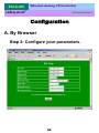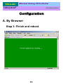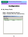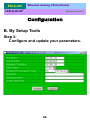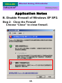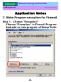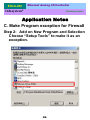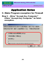
1
EIO-A-200
Ethernet Analog I/O
User Manual
Version 1.1
Infosystem Technology Corporation, Ltd.
EIO-A-200
Ethernet Analog I/O Controller
Infosystem®
(Preliminary Version)
Index
1. Disclaimers .......................... 1.
A. Warranty ......................... 2.
B. Trademark ........................ 2.
2. Product Information ....................... 3.
A. Introduction ........................ 3.
B. Features ......................... 4.
C. Applications ....................... 5.
3. Exterior ........................... 6.
A. Overview ......................... 6.
B. Front Panel ........................ 7.
C. Dimension ........................ 7.
4. Specifications ......................... 8.
A. Basic Specifications ..................... 8.
- Part 1 ....................... 8.
- Part 2 ....................... 9.
B. LED Indicator and Switch Description .............. 10.
- Top View ..................... 10.
- Description ..................... 11.
C. Wiring .......................... 12.
- Analog Input Channels ................. 12.
- DC 0.5A Digital Output x 2 (DO1, DO2) ........... 13.
D. ModBus Holding Register Definition .............. 14.
5. Software Installation ....................... 23.
A. Install ......................... 23.
- Step 1: Insert the CD and click the button ........... 23.
- Step 2: Click the Link of the Page ............. 24.
- Step 3: Press Next to Continue .............. 25.
- Step 4: Decide the Application Directory ........... 26.
- Step 5: Create the Directory if not existent .......... 27.
- Step 6: Create Program’s Shortcut ............. 28.
EIO-A-200
Infosystem®
Ethernet Analog I/O Controller
(Preliminary Version)
- Step 7: Decide if Desktop icon needed ............
- Step 8: Press Install to start installation ...........
- Step 9: Process Installations ...............
- Step 10: Finish Installation ...............
B. Uninstall .........................
- Step 1: Execute Uninstall Program .............
- Step 2: Click “Yes” to process ...............
- Step 3: Finished ....................
6. Configuration..........................
A. By Browser ........................
- Step 1: Ready to login .................
- Step 2: Configure your parameters .............
- Step 3: Finish and reboot ................
B. By Setup Tools ......................
- Step 1: Searching the devices ...............
- Step 2: Double click the selected item ............
- Step 3: Configure and update your parameters .........
C. By Direct Broadcast Commands ................
- Command List A ....................
- Command List B ...................
- Command List C ...................
7. Application Notes ........................
A. Description .......................
B. Disable Firewall of Windows XP SP2 ..............
- Step 1: Execute "Windows Firewall" .............
- Step 2: Close the Firewall ................
C. Make Program exception for Firewall ...............
- Step 1: Choose "Exception" ...............
- Step 2: Add on New Program ...............
- Step 3: Allow "Accept Any Computer" ............
- Step 3: Finished....................
29.
30.
31.
32.
33.
33.
34.
34.
35.
35.
35.
36.
37.
38.
38.
38.
39.
40.
40.
41.
42.
43.
43.
43.
43.
44.
45.
45.
46.
47.
48.
EIO-A-200
Ethernet Analog I/O Controller
Infosystem®
(Preliminary Version)
Disclaimers
The information in this manual has been carefully checked
and is believed to be accurate. Infosystem Technology
Corporation, Ltd. assumes no responsibility for any
infringements of patents or other rights of third parties,
which may result from its use.
Infosystem assumes no responsibility for any inaccuracies
that may be contained in this document. Infosystem makes
no commitment to update or to keep current the
information contained in this manual.
Infosystem reserves the right to make improvements to this
document and/or product at any time without notice.
No part of this publication may be reproduced, stored in a
retrieval system, or transmitted in any form of or by any
means, electronic, mechanical, photocopying, recording, or
otherwise, without the prior written permission of
Infosystem Technology Corporation, Ltd.
Copyright © 2006
Infosystem Technology Corporation, Ltd.
All rights reserved. Printed in Taiwan.
1.
EIO-A-200
Ethernet Analog I/O Controller
Infosystem®
(Preliminary Version)
Warranty
All products manufactured by Infosystem are warranted
against defective materials for a period of one year from the
date of delivery to the original purchaser.
Trademark
The names used for identification only maybe registered
trademark of their respective companies.
2.
EIO-A-200
Ethernet Analog I/O Controller
Infosystem®
(Preliminary Version)
Product Information
A. Introduction
EIO is an I/O controller product with Ethernet Port on
its data communication and makes data acquisition
easier through ModBus/TCP Protocol on Ethernet
network. For different conditions, EIO basically has
been designed into four models. EIO-R is Relay I/O
Controller. EIO-A is Analog I/O Controller. EIO-D is
Digital I/O Controller. And EIO-T is Thermocouple I/O
Controller. By using these products, the controlling and
monitoring of distributed control system can easily be
accomplished.
EIO-A-200 uses 8051’s family microprocessor for
implementing Ethernet functions. It uses the state
machine to handle TCP/IP stack with most but limited
functions because of the limited resources. EIO-A-200
supports ARP, ICMP, TCP, UDP, IP, DHCP-Client and
even HTTP protocols. You can use any browsers to set
the parameters, or just use the commands in console
mode. With no doubt, EIO-A-200 will bring you the
best integration in your applications.
3.
EIO-A-200
Ethernet Analog I/O Controller
Infosystem®
(Preliminary Version)
Product Information
B. Features
¾ Easy Configuration Setting
9 Use Setup Tools to Configure the Settings
9 Use HTTP, IE/Netscape Browser for Setting
¾ Good Security Concerned
9 Setup Login in Password Protect
9 Access Password Protect
¾ High Reliability
9 Stable and Robust
9 Working 24Hours per day
¾ Support Necessary Network Protocols
9 ARP, ICMP, TCP, UDP, IP, DHCP Client, HTTP
¾ Support ModBus Protocol
9 ModBus/TCP, ModBus/RTU, ModBus/ASCII
9 Easy integration with HMI/SCADA or OPC Server
¾ Multi-Channel and High Resolution
9 8 single-ended input channel with 16-bit resolution
¾ Support Four Operation Module
9
9
9
9
Voltage Inputs: 0~10V
Voltage Inputs: 1-5V
Current Inputs: 0~20mA
Current Inputs: 4~20mA
¾ Built-in high/low limitation detection capabilities
9 Users Engineering Limitations could be manually adjusted.
4.
EIO-A-200
Ethernet Analog I/O Controller
Infosystem®
(Preliminary Version)
Product Information
C. Applications
¾
¾
¾
¾
¾
¾
¾
¾
¾
¾
¾
¾
¾
¾
¾
¾
Data collection and Security Terminals
Access Control Terminals
Security Devices
Time Recorders
Warehouse Terminals
Shop floor automation Terminals
Remote Sensors and Meters
Power monitors
Power meters
Environmental monitors
Temperature monitors
Data loggers
Auto-ID Scanners
Barcode Scanners
Magnetic Card Readers
Basic Input/Output Operation
5.
EIO-A-200
Ethernet Analog I/O Controller
Infosystem®
(Preliminary Version)
Exterior
A. Overview
RJ-45 Ethernet Port
Analog Input
LED
Indicator
Discrete Output
LED
DC 24V
Power Input
Dip Switch
Analog Input
6.
Discrete Output
EIO-A-200
Ethernet Analog I/O Controller
Infosystem®
(Preliminary Version)
Exterior
B. Front Panel
a. Connector 1 (CONN1)
b. 10 BASE-T Ethernet
c. Discrete Output LED Indication
d. LED Indicator
e. Connector 2 (CONN2)
C. Dimension
94.0
80.0
33.0
50.0
102.0
4 xψ3.0
9.0
7.
(UNIT: mm)
Ethernet Analog I/O Controller
EIO-A-200
Infosystem®
(Preliminary Version)
Specifications
A. Basic Specifications
– Part 1 –
Entry
Network Interface
Protocol
Number of channels
Input ranges
Description
10BaseT, RJ-45
ARP, ICMP, TCP, UDP, IP, DHCP Client, HTTP,
Modbus/TCP
8 (differential input)
0-10V, 1-5V (input impedance 10MΩ)
0-20mA, 4~20mA (input impedance 250Ω)
Resolution
16 bit
Inaccuracy
±0.2% max at 25℃
Zero drift
+/-0.06 μV/℃
Span drift
+/-30 PPM/℃
Conversion speed
800 ms/8 channel
Channel isolation
Non-isolated (one common)
Power consumption
Range selection
0.2A
Dip switches
Number of output points 2 points
Insulation method
Photo coupler
Rated load voltage
24VDC
Type
NPN/Sink
8.
EIO-A-200
Ethernet Analog I/O Controller
Infosystem®
(Preliminary Version)
Specifications
A. Basic Specifications
– Part 2 –
Entry
Description
Max. load current
0.5A/pt
Leakage current at OFF circuit
0.1mA or less
Max. voltage drop at ON circuit
1.5V or less
Response time
OFF Æ ON
8 msec or less
ON Æ OFF
8 msec or less
Voltage
2 points/common
24VDC (21.6VDC~26.4VDC)
Current
100mA
Common terminal arrangement
External power supply
International current consumption
50 mA (type, all points on)
Operating temperature
0 ~60℃
Storage temperature
-20 ~ 80℃
Relative humidity
15 ~ 95 % RH (non-condensing)
Environment air
Voltage
No corrosive gases permitted
24Vdc (7Vdc~36Vdc)
Current
80mA
External power supply
International current consumption
9.
50 mA (type, all points on)
Ethernet Analog I/O Controller
EIO-A-200
Infosystem®
(Preliminary Version)
Specifications
B. LED Indicator and Switch Description
– Top View –
9
CONN1
1
Ethernet
DO1
DO2
SYS
TOP View
RX
TX
LINK
SW
1
CONN2
12
10.
13
Ethernet Analog I/O Controller
EIO-A-200
Infosystem®
(Preliminary Version)
Specifications
B. LED Indicator and Switch Description
– Description –
LED Indicator:
LED
Description
SYS
The SYS LED blinks at a rate of 1.5Hz and indicating normal work.
RX
Received data.
TX
Transmitted data.
LINK
DO1~DO2
If ON, the Ethernet connection is activated.
The DC outputs1~2.
Switch Description: Defining Operation Range
Users may set the positions of the dip switches which are located on the
bottom side of the module to choose one of the operation ranges
provided by the EIO-A-200 module.
SW1
SW2
EIO-A-200 OPERATION RANGE
ON
OFF
Voltage inputs: 0~10V
ON
ON
Voltage inputs: 1~5V
OFF
OFF
Current inputs: 0~20mA
OFF
ON
Current inputs: 4~20mA
11.
Ethernet Analog I/O Controller
EIO-A-200
Infosystem®
(Preliminary Version)
Specifications
C. Wiring
Users may refer to the following diagram to connect the
external wiring for the EIO-A-200 module. (Wires for analog
input signals are recommended to have the shielding
protection)
– Analog Input Channels–
CH1+
1
9
CONN1
1
CH1-
Ethernet
CH2+
CH2-
CONN1
CH3+
CH3-
DO1
CH4+
DO2
CH4AGND
9
CH5+
1
SYS
EIO-A-200
RX
TX
LINK
CH5CH6+
CH6CH7+
CONN2
CH7CH8+
CH8-
8
~~
~~
13
SW
1
12
12.
CONN2
13
EIO-A-200
Ethernet Analog I/O Controller
Infosystem®
(Preliminary Version)
Specifications
C. Wiring
– DC 0.5A Digital Output x 2 (DO1, DO2) –
13.
EIO-A-200
Ethernet Analog I/O Controller
Infosystem®
(Preliminary Version)
Specifications
D. ModBus Holding Register Definition
The EIO-A-200 module provides 11 registers (words) for users to access
the status of the module and read the data from the input channels or
write the data to the output register. These 11 registers are called scan
data registers. The definitions of the 11 registers are described as
follows:
EIO-A-200 Scan Data Address
(ModBus Holding Register
Address)
Description
40001
Digital Output Register
40003
Line Broken Detection Flags
40004
Status Register
40005
Channel 1 Input Register
40006
Channel 2 Input Register
40007
Channel 3 Input Register
40008
Channel 4 Input Register
40009
Channel 5 Input Register
40010
Channel 6 Input Register
40011
Channel 7 Input Register
40012
Channel 8 Input Register
14.
EIO-A-200
Ethernet Analog I/O Controller
Infosystem®
(Preliminary Version)
Specifications
D. ModBus Holding Register Definition
Digital output register: (40001)
Bit 1: DO1 output status
Bit 2: DO2 output status
Bit 3 to Bit 16 are reserved.
Line broken detection flags: (40003)
Bit1 ~ Bit8 are corresponding to the channel 1 ~ channel 8
Bit status = 1 (line broken)
= 0 (normal)
Status (flag) register: (40004)
Bit 1: low limitation flag of channel 1
Bit 2: high limitation flag of channel 1
Bit 3: low limitation flag of channel 2
Bit 4: high limitation flag of channel 2
Bit 5: low limitation flag of channel 3
Bit 6: high limitation flag of channel 3.
Bit 7: low limitation flag of channel 4
Bit 8: high limitation flag of channel 4
Bit 9: low limitation flag of channel 5
Bit 10: high limitation flag of channel 5
Bit 11: low limitation flag of channel 6
Bit 12: high limitation flag of channel 6
Bit 13: low limitation flag of channel 7
Bit 14: high limitation flag of channel 7
Bit 15: low limitation flag of channel 8
Bit 16: high limitation flag of channel 8
15.
EIO-A-200
Ethernet Analog I/O Controller
Infosystem®
(Preliminary Version)
Specifications
D. ModBus Holding Register Definition
Besides the scan data registers, the EIO-A-200 module also provides other
Modbus holding registers for users to fill in the high/low limit value and define
the conversion data type. High- and low-limit values will be used by the
module for comparing the channel’s input signal to detect if the input signal is
higher or lower than the limitation value set by the user. If the value of an input
channel is higher or lower than the corresponding data stored in these holding
registers, the corresponding flag bit of the status register in the scan data
registers will be set to ‘1’.
The conversion data for each channel may be represented by the raw
conversion data defined by the module or engineering data defined by users. If
users define the conversion data type to be an engineering data, users may set
the low engineering value and the high engineering value using the specified
holding registers from 40033~40048 for each of the input channel instead of
the raw data range defined by the module. The corresponding input signals will
be linearly converted to the engineering data corresponding to the defined
range of high/low engineering setting value to the corresponding channel input
registers in scan data registers.
Users will be requested to use the engineering data to define the high/low
limitation values for the corresponding channels if users select the conversion
data type with engineering data.
16.
EIO-A-200
Ethernet Analog I/O Controller
Infosystem®
(Preliminary Version)
Specifications
D. ModBus Holding Register Definition
Holding Register
Description
40013
Flags for control A/D conversion
40014
High/low limit control flags
40015
Low limitation value of CH1
40016
High limitation value of CH1
40017
Low limitation value of CH2
40018
High limitation value of CH2
40019
Low limitation value of CH3
40020
High limitation value of CH3
40021
Low limitation value of CH4
40022
High limitation value of CH4
40023
Low limitation value of CH5
40024
High limitation value of CH5
40025
Low limitation value of CH6
40026
High limitation value of CH6
40027
Low limitation value of CH7
40028
High limitation value of CH7
40029
Low limitation value of CH8
40030
High limitation value of CH8
40031
Reserved
17.
EIO-A-200
Ethernet Analog I/O Controller
Infosystem®
(Preliminary Version)
Specifications
D. ModBus Holding Register Definition
Holding Register
Description
40032
Conversion data type
(row data or engineering data)
40033
Low engineering setting value of CH1
40034
High engineering setting value of CH1
40035
Low engineering setting value of CH2
40036
High engineering setting value of CH2
40037
Low engineering setting value of CH3
40038
High engineering setting value of CH3
40039
Low engineering setting value of CH4
40040
High engineering setting value of CH4
40041
Low engineering setting value of CH5
40042
High engineering setting value of CH5
40043
Low engineering setting value of CH6
40044
High engineering setting value of CH6
40045
Low engineering setting value of CH7
40046
High engineering setting value of CH7
40047
Low engineering setting value of CH8
40048
High engineering setting value of CH8
18.
EIO-A-200
Ethernet Analog I/O Controller
Infosystem®
(Preliminary Version)
Specifications
D. ModBus Holding Register Definition
Conversion control/speed flags: (40013)
1. Bit 1 to Bit 8 are reserved.
2. Bit 9 to Bit 16 are A/D conversion control flags.
‘0’: enable A/D conversion (default)
‘1’: disable A/D conversion
19.
EIO-A-200
Ethernet Analog I/O Controller
Infosystem®
(Preliminary Version)
Specifications
D. ModBus Holding Register Definition
High/low limit control flags: (40014)
Bit 1: low limitation control bit for CH1
Bit 2: high limitation control bit for CH1
Bit 3: low limitation control bit for CH2
Bit 4: high limitation control bit for CH2
Bit 5: low limitation control bit for CH3
Bit 6: high limitation control bit for CH3
Bit 7: low limitation control bit for CH4
Bit 8: high limitation control bit for CH4
Bit 9: low limitation control bit for CH5
Bit 10: high limitation control bit for CH5
Bit 11: low limitation control bit for CH6
Bit 12: high limitation control bit for CH6
Bit 13: low limitation control bit for CH7
Bit 14: high limitation control bit for CH7
Bit 15: low limitation control bit for CH8
Bit 16: high limitation control bit for CH8
20.
EIO-A-200
Ethernet Analog I/O Controller
Infosystem®
(Preliminary Version)
Specifications
D. ModBus Holding Register Definition
Remarks:
1. If some bits of the high/low limit control flags are set to ‘1’, the input
Signals of corresponding channels will be compared with the corresponding
limitation values which were stored in the specified holding registers. If the
corresponding channel’s input value is higher or lower than the
corresponding limitation value stored in the specified holding register, the
corresponding flag bit of the status register (40004) will be set to ‘1’.
2. Users do not need to set the control bit or initiate the data to the specified
holding registers if high/low limit detection is not required in the
application.
Conversion data type: (40032)
Bit 1: CH1’s conversion data type
Bit 2: CH2’s conversion data type
Bit 3: CH3’s conversion data type
Bit 4: CH4’s conversion data type
Bit 5: CH5’s conversion data type
Bit 6: CH6’s conversion data type
Bit 7: CH7’s conversion data type
Bit 8: CH8’s conversion data type
21.
EIO-A-200
Ethernet Analog I/O Controller
Infosystem®
(Preliminary Version)
Specifications
D. ModBus Holding Register Definition
Remark:
1. The default status of the above bits is ‘0’. In other words, the default
conversion data type for each channel is raw data.
2. If some bits of the data conversion bits are set to ‘1’, the input signals of
corresponding channels will be converted to the corresponding engineering
data and stored to the channel input registers in scan data registers.
High/low engineering setting values: (40033~40048)
1. Users may fill in the low engineering values and high engineering values to
the corresponding holding registers from 40033 to 40048 for each of the
channel instead of the raw data range defined by the module. Users may
check the raw data conversion table in the following chapter.
2. If users set the module’s conversion data type to be an engineering data, the
module will use to the range of the high/low engineering setting values
defined by the users and linearly convert the input signal to the
corresponding engineering data to the corresponding channel input register
in the scan data register.
22.
EIO-A-200
Ethernet Analog I/O Controller
Infosystem®
(Preliminary Version)
Software Installation
A. Installation
Step 1: Insert the CD and click the button
The Software Installation CD that came with EIO-A-200 will
automatically be run after inserting it into the CD-ROM drive. Click
the “Ethernet converter Setup Utilities” button will bring the
installation page out,
Figure1. Software Install CD Auto-Run Screen Shot
23.
EIO-A-200
Ethernet Analog I/O Controller
Infosystem®
(Preliminary Version)
Software Installation
A. Installation
Step 2: Click the Link of the Page
Click the Link of the Page to run the Ethernet Converter Setup Tools
Installation Software.
Figure2. Ethernet Converter Setup Tools Page
24.
EIO-A-200
Ethernet Analog I/O Controller
Infosystem®
(Preliminary Version)
Software Installation
A. Installation
Step 3: Press Next to Continue
Figure3. Installation Welcome Message
25.
Ethernet Analog I/O Controller
EIO-A-200
Infosystem®
(Preliminary Version)
Software Installation
A. Installation
Step 4: Decide the Application Directory
Figure4. Decide the Application Directory
26.
EIO-A-200
Ethernet Analog I/O Controller
Infosystem®
(Preliminary Version)
Software Installation
A. Installation
Step 5: Create the Directory if not existent
Figure5. Create Application Directory
27.
EIO-A-200
Ethernet Analog I/O Controller
Infosystem®
(Preliminary Version)
Software Installation
A. Installation
Step 6: Create Program’s Shortcut
Figure6. Shortcut Creation
28.
EIO-A-200
Ethernet Analog I/O Controller
Infosystem®
(Preliminary Version)
Software Installation
A. Installation
Step 7: Decide if Desktop icon needed
Figure7. Desktop Icon Creation
29.
EIO-A-200
Ethernet Analog I/O Controller
Infosystem®
(Preliminary Version)
Software Installation
A. Installation
Step 8: Press Install to start installation
Figure8. Review the Installation Settings
30.
EIO-A-200
Ethernet Analog I/O Controller
Infosystem®
(Preliminary Version)
Software Installation
A. Installation
Step 9: Process Installations
Figure9. Installing
31.
EIO-A-200
Ethernet Analog I/O Controller
Infosystem®
(Preliminary Version)
Software Installation
A. Installation
Step 10: Finish Installation
Figure10. Installation Finished
32.
Ethernet Analog I/O Controller
EIO-A-200
Infosystem®
(Preliminary Version)
Software Installation
B. Uninstall
Step 1: Execute Uninstall Program
Uninstall Program is located at the application directory named
“Uninstall Ethernet Converter Setup”. Execution of it could let the
Ethernet Converter Setup Tools clearly be removed.
Figure11. Decide the Application Directory
33.
EIO-A-200
Ethernet Analog I/O Controller
Infosystem®
(Preliminary Version)
Software Installation
B. Uninstall
Step 2: Click “Yes” to process
Figure12. Process Uninstall
Step 3: Finished
Figure12. Process Uninstall
34.
EIO-A-200
Ethernet Analog I/O Controller
Infosystem®
(Preliminary Version)
Configuration
A.By Browser
Step 1: Ready to login.
35.
EIO-A-200
Ethernet Analog I/O Controller
Infosystem®
(Preliminary Version)
Configuration
A. By Browser
Step 2: Configure your parameters.
36.
EIO-A-200
Ethernet Analog I/O Controller
Infosystem®
(Preliminary Version)
Configuration
A. By Browser
Step 3: Finish and reboot.
37.
EIO-A-200
Ethernet Analog I/O Controller
Infosystem®
(Preliminary Version)
Configuration
B. By Setup Tools
Step 1: Searching the devices.
Step 2: Double click the selected item.
38.
EIO-A-200
Ethernet Analog I/O Controller
Infosystem®
(Preliminary Version)
Configuration
B. By Setup Tools
Step 3:
Configure and update your parameters.
39.
EIO-A-200
Ethernet Analog I/O Controller
Infosystem®
(Preliminary Version)
Configuration
C. By Direct Broadcast Commands
It needs broadcasting to handle all the
configurations and it allows users to code their
own application software.
– Command List A – User Level –
–
Command
X or x
Description
Notes
Purpose
Syntax
Magic code
Return
For Broadcast search
Example
G or g
Purpose
Syntax
Return
X <magic code>
99.130.83.99
AX <MAC>/<IP>/<Device ID>
Send
X 99.130.83.99
Back
AX 0.128.200.255.251.242/192.168.1.1/1
Get all the parameters of the WM-110
G <MAC>/<IP>/<Setup Password>
All the parameters of the WM-110
Send
Example
Back
G 0.128.200.255.251.242/192.168.1.1/123
CG for cancel
AG<All Messages>
40.
EIO-A-200
Ethernet Analog I/O Controller
Infosystem®
(Preliminary Version)
Configuration
C. By Direct Broadcast Commands
User Level:
Admin Level:
For General Users
For Factory Default Setting
– Command List B – User Level –
Command Description Notes
Purpose
Syntax
S
Return
Example
Purpose
Syntax
R
Return
Example
Set the parameters of WM-110
S <MAC>/<IP>/<Password>/<Parameter>/<Value>
A for accept
C for cancel
Send
S 0.128.200.255.251.242/192.168.1.1/123/IP/192.168.1.2
Back
A or C
Reboot WM-110
R <MAC>/<IP>/<Setup Password>
AR for accept
CR for cancel
Send
R 0.128.200.255.251.242/192.168.1.1/123
Back
AR or CR
41.
EIO-A-200
Ethernet Analog I/O Controller
Infosystem®
(Preliminary Version)
Configuration
C. By Direct Broadcast Commands
User Level:
Admin Level:
For General Users
For Factory Default Setting
– Command List C – Admin Level –
Command Description Notes
Purpose
Syntax
M
Return
Example
Purpose
Syntax
I
Return
Example
Set MAC address of WM-110 then reboot automatically
M <Old MAC>/<New MAC>/<Factory Password>
AM for accept
CM for cancel
Send
S 0.128.200.255.251.242/0.128.200.255.251.243/123
Back
‘A’ or ‘C’
Set IP for Factory settings
I <MAC>/<New IP>/<Factory Password>
AI for accept
CI for cancel
Send
I 0.128.200.255.251.242/192.168.1.1/123’
Back
AR or CR
42.
EIO-A-200
Ethernet Analog I/O Controller
Infosystem®
(Preliminary Version)
Application Notes
A. Description:
Firewall will make the program off normal, so
one might choose the following solutions to
Firewall program, “Disable” or “Exception”.
B. Disable Firewall of Windows XP SP2.
Step 1: Execute "Windows Firewall"
Execute “Windows Firewall” in Control
Panel.
43.
EIO-A-200
Ethernet Analog I/O Controller
Infosystem®
(Preliminary Version)
Application Notes
B. Disable Firewall of Windows XP SP2.
Step 2: Close the Firewall
Choose “Close” to close firewall.
44.
EIO-A-200
Ethernet Analog I/O Controller
Infosystem®
(Preliminary Version)
Application Notes
C. Make Program exception for Firewall
Step 1: Choose "Exception"
Choose “Exception” in Firewall Program.
And add on new program of Setup Tools.
45.
EIO-A-200
Ethernet Analog I/O Controller
Infosystem®
(Preliminary Version)
Application Notes
C. Make Program exception for Firewall
Step 2: Add on New Program and Selection
Choose “Setup Tools” to make it as an
exception.
46.
EIO-A-200
Ethernet Analog I/O Controller
Infosystem®
(Preliminary Version)
Application Notes
C. Make Program exception for Firewall
Step 3: Allow "Accept Any Computer"
Allow “Accept Any Computer” to finish
exception.
47.
EIO-A-200
Ethernet Analog I/O Controller
Infosystem®
(Preliminary Version)
Application Notes
C. Make Program exception for Firewall
Step 4: Finished
Finish Exception.
48.
Infosystem®
Copyright © 2006
Infosystem Technology Corporation, Ltd.
No. 45, Lane 167, Dongnan St.
Hsinchu, Taiwan 300, R.O.C.
TEL: +886-3-562-7187
FAX: +886-3-561-1435
Service E-mail: [email protected]
Web page URL:http://www.infosystem.com.tw