1
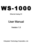
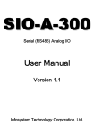
SIO-D-310
Serial (RS485) Digital I/O
User Manual
Version 1.1
Infosystem Technology Corporation, Ltd.
SIO-D-310M
Serial (RS485) Digital I/O Controller
Infosystem®
(Preliminary Version)
Index
1. Disclaimers .......................... 1.
A. Warranty ......................... 2.
B. Trademark ........................ 2.
2. Product Information ....................... 3.
A. Introduction ........................ 3.
B. Features ......................... 4.
3. Exterior ........................... 6.
A. Front View ........................ 6.
B. Back View ........................ 7.
C. Top View ........................ 8.
D. Front Panel ........................ 9.
E. Dimension ........................ 9.
4. Specifications ......................... 10.
A. Basic Specification ..................... 10.
B. Digital Input Specfication ................... 11.
C. Digital Output Specification .................. 12.
D. LED Indicator and Switch Description .............. 13.
- Top View ...................... 13.
- Led Indicator ..................... 14.
- Switch Description ................... 14.
E. PIN Definition and Wiring ................... 15.
- Panel PIN Definition .................. 15.
- PIN Description .................... 16.
- Equivalent Input Circuit ................. 17.
- Equivalent Output Circuit ................ 18.
F. ModBus Definitions ..................... 19.
- Output Status Definition ................. 19.
- Input Status Definition ................. 20.
- Input Register Definition ................. 21.
- Holding Register Definition ................ 22.
SIO-D-310M
Infosystem®
Serial (RS485) Digital I/O Controller
(Preliminary Version)
G. Modbus Definition Description.................
5. Configuration .........................
A. Console Mode Description ..................
- Step 1: Main Menu...................
- Step 2: Restore Default Factory Value ............
- Step 3: Show Device Configuration .............
- Step 4: Set Device Configuration ..............
- Step 5: Set Input Device ID ................
- Step 6: Setting Data bits, Parity Check and Stop Bit .......
- Step 7: Make sure to save the Configuration .........
- Step 8: Exit and Run System Program ............
23.
25.
25.
25.
26.
27.
28.
29.
30.
31.
32.
SIO-D-310M
Serial (RS485) Digital I/O Controller
Infosystem®
(Preliminary Version)
Disclaimers
The information in this manual has been carefully checked
and is believed to be accurate. Infosystem Technology
Corporation, Ltd. assumes no responsibility for any
infringements of patents or other rights of third parties,
which may result from its use.
Infosystem assumes no responsibility for any inaccuracies
that may be contained in this document. Infosystem makes
no commitment to update or to keep current the
information contained in this manual.
Infosystem reserves the right to make improvements to this
document and/or product at any time without notice.
No part of this publication may be reproduced, stored in a
retrieval system, or transmitted in any form of or by any
means, electronic, mechanical, photocopying, recording, or
otherwise, without the prior written permission of
Infosystem Technology Corporation, Ltd.
Copyright © 2006
Infosystem Technology Corporation, Ltd.
All rights reserved. Printed in Taiwan.
1.
SIO-D-310M
Serial (RS485) Digital I/O Controller
Infosystem®
(Preliminary Version)
Warranty
All products manufactured by Infosystem are warranted
against defective materials for a period of one year from the
date of delivery to the original purchaser.
Trademark
The names used for identification only maybe registered
trademark of their respective companies.
2.
SIO-D-310M
Serial (RS485) Digital I/O Controller
Infosystem®
(Preliminary Version)
Product Information
A. Introduction
SIO is an I/O controller product with Serial Port on its data
communication and makes data acquisition easier through
ModBus Protocol of RTU/ASCII mode on Serial Bus. For
different conditions, SIO basically has been design into
four models. SIO-R is Relay type I/O Controller. SIO-A is
Analog I/O. SIO-D is Digital I/O. And SIO-T is
Temperature I/O Controller. By using these products, the
controlling and monitoring of distributed control system
can easily be accomplished.
SIO-D-310M uses the MSP430 microprocessor family for
implementing the whole framework. Basically, it supports
up to 10 inputs, and 8 outputs. Moreover, it equips the
counter function in each input channels, and is also
designed for friendly use and convenience concerns. With
no doubt, SIO-D-310M will bring you the best integration
in your applications.
3.
SIO-D-310M
Serial (RS485) Digital I/O Controller
Infosystem®
(Preliminary Version)
B. Features
¾ Support ModBus Protocol
9 Auto Detect ModBus RTU and ASCII Mode
9 Modbus Function Supported:
-
0x01: Read Coil Status
0x02: Read Input Status
0x03: Read Holding Registers
0x04: Read Input Registers
0x05: Force Single Coil
0x06: Preset Single Register
0x0F: Force Multiple Coils
0x10: Preset Multiple Registers
¾ Configurable Parameters
9 Configurable Device ID
-
Configure by Hardware DIP Switch
Configure by Console or ModBus (When DIP Device ID = 0)
9 Configurable Serial Ports
-
Baud Rate:
300 ~ 115200 bps
(57600 bps with counter function enabled.)
Word Length: 7 or 8 bits
Parity Check: None, even or odd
Stop Bit:
1 or 2 bits
4.
SIO-D-310M
Serial (RS485) Digital I/O Controller
Infosystem®
(Preliminary Version)
B. Features
¾ High Reliability
9 Stable and Robust
9 Working 24-Hours per day
¾ Insulation Input and Output
9 DC 24V (50V option)Photo Couple Insulation Input x 10
9 DC 0.5A Photo Couple Insulation Output x 8
¾ Digital Counter Function
9 Use DIP Switch to enable/disable Counter Function.
9 Each Input will enable Counter Function simultaneously
when DIP Switch select to enable Counter Function.
¾ User Defined Registers
9 User Defined Registers for Customizations x 10
(Holding Register: 40011 ~ 40020)
9 Frequency Registers for each input with Counter Function.
(Holding Register: 40021 ~ 40030)
9 Counting Registers for each input with Counter Function.
(Holding Register: 40031 ~ 40050)
5.
Serial (RS485) Digital I/O Controller
SIO-D-310M
Infosystem®
(Preliminary Version)
Exterior
A. Front View
Connector 1
RS485
FRONT VIEW
Connector 2
ON
1
2
12
6.
SIO-D-310M
Serial (RS485) Digital I/O Controller
Infosystem®
(Preliminary Version)
Exterior
B. Back View
RS485
Connector 1
BACK VIEW
ON 1
2
3
4
5
6
7
8
87654321
Connector 2
ON 1
2
21
7.
SIO-D-310M
Serial (RS485) Digital I/O Controller
Infosystem®
(Preliminary Version)
Exterior
C. Top View
8.
Serial (RS485) Digital I/O Controller
SIO-D-310M
Infosystem®
(Preliminary Version)
Exterior
D. Front Panel
a
b
a. RS485 Port
b. CONN1 and Digital Input LED
c. Digital Output LED Indicator
d
d. System LED Indicators
c
e. Function DIP Switch
b
f
e
f. CONN2
E. Dimension
93.1
67.2
33.4
50.0
101.1
4 xψ3.0
(UNIT: mm)
9.0
9.
SIO-D-310M
Serial (RS485) Digital I/O Controller
Infosystem®
(Preliminary Version)
Specification
A. Basic Specification
Entry
Communication Interface
Protocol
Description
RS485
Modbus/RTU, Modbus/ASCII
Watch Dog
Auto Reset Function
Discrete I/O
10 points, DC 24V Input (DC 50V Input Option)
8 points, DC 0.5A Output
Led Indication
SYS x1 (Red), TX x 1 (Green), RX x 1 (Green)
Power Requirement
24V DC
Power consumption
< 1W
Temperature
Humidity
Dimension
Configuration
Operation: 0ºC~+55º C (32ºF~+131ºF)
Storage: -20ºC~+70ºC (-4ºF~+158ºF)
15% to 95% (non-condensing)
100mm x 68mm x 33mm
Through Console mode or Modbus
10.
SIO-D-310M
Serial (RS485) Digital I/O Controller
Infosystem®
(Preliminary Version)
Specification
B. Digital Input Specification
Entry
Description
10 points
Number of Input Points
Photo Couple
Isolated Method
Rated Input Voltage
24V DC (50V DC option)
Rated Input Current
7 mA
21.6V DC ~ 26.4V DC
Operation Voltage Range
Turn ON State
12V DC / 2 mA or higher
Turn OFF State
4V DC / 1 mA or lower
Approx. 3.9 KΩ
Input Impedance
Response Time
OFF Æ ON
8 msec or less (24 VDC)
ON Æ OFF
8 msec or less (24 VDC)
Common Terminal Arrangement
10 points / common
MAX. 100 mA (type, all points ON)
Internal Current Consumption
11.
SIO-D-310M
Serial (RS485) Digital I/O Controller
Infosystem®
(Preliminary Version)
Specification
C. Digital Output Specification
Entry
Description
8 points
Number of Input Points
Photo Couple
Isolated Method
24V DC
Rated Load Voltage
21.6V DC ~ 26.4V DC
Operation Voltage Range
NPN / Sink
Type
0.5 A/pt
Max. Load Current
Leakage Current at OFF Circuit
0.1 mA or less
Max. Voltage Drop at ON Circuit
1.5V or less
Response Time
OFF Æ ON
8 msec or less
ON Æ OFF
8 msec or less
Common Terminal Arrangement
External Power Supply
8 points / common
Voltage
24V DC (21.6V DC ~ 26.4V DC)
Current
100 mA
International Current Consumption
12.
Max. 100 mA (type, all points on)
SIO-D-310M
Serial (RS485) Digital I/O Controller
Infosystem®
(Preliminary Version)
Specification
D. LED Indicator and Switch Description
– Top View –
RS485
G – ﹢
IN1
IN2
IN3
1
IN4
IN5
IN6
IN7
CONN1
IN8
9
OUT1
OUT2
OUT3
SYS
OUT4
RX
OUT5
TX
OUT6
OUT7
SIO-D-310M
IN10
IN9
OUT8
SW
1
CONN2
12
13.
13
Serial (RS485) Digital I/O Controller
SIO-D-310M
Infosystem®
(Preliminary Version)
Specification
D. LED Indicator and Switch Description
– Led Indicator –
LED
SYS
RX
TX
DI1 ~ DI10
DO1 ~ DO8
Description
The SYS LED blinks at a rate of 2Hz at normal work.
And 4Hz at Console Mode. Red Light.
Blinks when receiving data.
Blinks when transmitting data.
Digital Input Indicator LED. ON status refers to high voltage input.
Digital Output Indicator LED. ON status refers to low voltage output.
– Switch Description –
2-PIN SWITCH: For Mode Selections
PIN \ Status
ON
OFF
SW-1
Console Mode
Operation / Modbus Mode
SW-2
Enable Counter
Disable Counter
8-PIN SWITCH: For Hardware Device ID
PIN Def.
PIN 1
PIN 2
PIN 3
PIN 4
PIN 5
PIN 6
PIN 7
PIN 8
1
1
1
1
1
1
1
1
Status Value
ON
OFF
Exp. Value
0
20
0
21
0
22
0
23
0
24
0
25
0
26
Device ID = Sum of Corresponded Entry Value (Status Value x Exp. Value).
Example: PIN1, PIN2 ON, PIN3~PIN8 OFF --> Device ID = 20x1+21x1 = 3
14.
0
27
SIO-D-310M
Serial (RS485) Digital I/O Controller
Infosystem®
(Preliminary Version)
Specification
E. PIN Definition and Wiring
Users may refer to the following diagram to connect the
external wiring for the SIO-R-310M module.
– Panel PIN Definition –
DI1
DI2
9
1
CONN1
1
RS485
G – ﹢
DI6
OUT2
9
IN1
IN2
IN3
SW8
OUT3
OUT4
DI9
IN4
OUT1
DI7
24G
IN5
CONN1
DI5
DI8
IN6
DI4
IN7
IN8
DI3
1
OUT5
DI10
DO1
OUT6
DO2
OUT7
DO3
OUT8
DO4
IN9
DO6
RX
TX
SIO-D-310M
IN10
CONN2
DO5
1 2 3 4 5 6 7 8
SYS
DO7
DO8
SW
24V
24G
FG
13
1
CONN2
12
15.
13
SIO-D-310M
Serial (RS485) Digital I/O Controller
Infosystem®
(Preliminary Version)
Specification
E. PIN Definition and Wiring
– PIN Description –
Entry
CONN1
DI1 ~ DI8
CONN1
GND
CONN2
DI9 ~ DI10
CONN2
DO1 ~ DO8
Description
Digital Input (DC 24V) Point 1~8
Use as 24V DC Ground.
Digital Input (DC 24V) Point 9~10
Digital Output (DC 24V) Point 1~8
24V
Input Power of DC 24V.
24G
Ground of Input Power of DC 24V
FG
Field Ground
16.
SIO-D-310M
Serial (RS485) Digital I/O Controller
Infosystem®
(Preliminary Version)
Specification
E. PIN Definition and Wiring
– Equivalent Input Circuit –
17.
SIO-D-310M
Serial (RS485) Digital I/O Controller
Infosystem®
(Preliminary Version)
Specification
E. PIN Definition and Wiring
– Equivalent Output Circuit –
18.
SIO-D-310M
Serial (RS485) Digital I/O Controller
Infosystem®
(Preliminary Version)
Specification
F. Modbus Definitions
The discrete I/O points of the SIO-D-310M can easily be controlled and
monitored through Modbus protocol. The Modbus address mapping with
discrete I/O is described as the followings.
– Output Status Definition –
Output Status (Coil Status, ON=1, OFF=0)
Address
Description
00001
00002
00003
00004
00005
00006
00007
00008
DO1, OUT1 Status
DO2, OUT2 Status
DO3, OUT3 Status
DO4, OUT4 Status
DO5, OUT5 Status
DO6, OUT6 Status
DO7, OUT7 Status
DO8, OUT8 Status
19.
SIO-D-310M
Serial (RS485) Digital I/O Controller
Infosystem®
(Preliminary Version)
Specification
F. Modbus Definitions
– Input Status Definition –
Output Status (Coil Status, ON=1, OFF=0)
Address
Description
10001
DI1, IN1 Status
10002
DI2, IN2 Status
10003
DI3, IN3 Status
10004
DI4, IN4 Status
10005
DI5, IN5 Status
10006
DI6, IN6 Status
10007
DI7, IN7 Status
10008
DI8, IN8 Status
10009
DI9, IN9 Status
10010
DI10, IN10 Status
20.
SIO-D-310M
Serial (RS485) Digital I/O Controller
Infosystem®
(Preliminary Version)
Specification
F. Modbus Definitions
– Input Register Definition –
Input Registers (For Counter Function)
Address
30001
30002
30003
30004
30005
30006
30007
30008
30009
30010
Definition
DI1 Pulse
Frequency
DI2 Pulse
Frequency
DI3 Pulse
Frequency
DI4 Pulse
Frequency
DI5 Pulse
Freq.
DI6 Pulse
Frequency
DI7 Pulse
Frequency
DI8 Pulse
Frequency
DI9 Pulse
Frequency
DI10 Pulse
Frequency
Address
30011
30012
30013
30014
30015
30016
30017
30018
30019
30020
Definition
DI1 Count
Low Byte
DI1 Count
High Byte
DI2 Count
Low Byte
DI2 Count
High Byte
DI3 Count
Low Byte
DI3 Count
High Byte
DI4 Count
Low Byte
DI4 Count
High Byte
DI5 Count
Low Byte
DI5 Count
High Byte
21.
Address
30021
30022
30023
30024
30025
30026
30027
30028
30029
30030
Definition
DI6 Count
Low Byte
DI6 Count
High Byte
DI7 Count
Low Byte
DI7 Count
High Byte
DI8 Count
Low Byte
DI8 Count
High Byte
DI9 Count
Low Byte
DI9 Count
High Byte
DI10 Count
Low Byte
DI10 Count
High Byte
SIO-D-310M
Serial (RS485) Digital I/O Controller
Infosystem®
(Preliminary Version)
Specification
F. Modbus Definitions
– Holding Register Definition –
Address
40001
40002
40003
40004
40005
40006
40007
40008
40009
40010
40011
40012
40013
40014
40015
40016
40017
40018
40019
40020
40021
40022
40023
40024
40025
Holding Register Definition
Definition
Address
Output Register
40026
Input Register
40027
Device ID
40028
Baud Rate
40029
Word Length
40030
Parity Check
40031
Stop Bit
40032
Write Data Command
40033
Write Data Status
40034
RS485 Change on-line
40035
User Defined Register
40036
User Defined Register
40037
User Defined Register
40038
User Defined Register
40039
User Defined Register
40040
User Defined Register
40041
User Defined Register
40042
User Defined Register
40043
User Defined Register
40044
User Defined Register
40045
DI1 Input Frequency
40046
DI2 Input Frequency
40047
DI3 Input Frequency
40048
DI4 Input Frequency
40049
DI5 Input Frequency
40050
22.
Definition
DI6 Input Frequency
DI7 Input Frequency
DI8 Input Frequency
DI9 Input Frequency
DI10 Input Frequency
DI1 Count (Low Byte)
DI1 Count (High Byte)
DI2 Count (Low Byte)
DI2 Count (High Byte)
DI3 Count (Low Byte)
DI3 Count (High Byte)
DI4 Count (Low Byte)
DI4 Count (High Byte)
DI5 Count (Low Byte)
DI5 Count (High Byte)
DI6 Count (Low Byte)
DI6 Count (High Byte)
DI7 Count (Low Byte)
DI7 Count (High Byte)
DI8 Count (Low Byte)
DI8 Count (High Byte)
DI9 Count (Low Byte)
DI9 Count (High Byte)
DI10 Count (Low Byte)
DI10 Count (High Byte)
SIO-D-310M
Serial (RS485) Digital I/O Controller
Infosystem®
(Preliminary Version)
Specification
G. Modbus Definition Description
Addr.
00001
~
00006
10001
~
10008
30001
~
30010
30011
~
30030
40001
40002
Att.
Functions
Description
0x01 Read Coil Status
R/W
0x05 Force Single Coil
0x0F Force Multiple Coil
Read
Only
0x02 Read Input Status
Read
Only
0x04 Read Input Registers
Read
Only
0x04 Read Input Registers
R/W
Read
Only
Note
DO1 ~ DO6 ON / OFF
ON=1, OFF=0
Status and Control
No of Point <= 8
DI1 ~ DI10 High / Low
High=1, Low=0
Status
No of Point <= 10
Detect the Frequency of Input
Frequency Upper
Pulse
Bound at 250 Hz.
Counter Value for DI
Odd Address (Low Byte)
Count for 32 bit
Even Address (High Byte)
0x03 Read Holding Registers
DO1 ~ DO6 ON / OFF
ON=1, OFF=0
0x06 Preset Single Register
Status and Control
BIT0=DO1,…BIT8=D
0x10 Preset Multiple Registers
In Bit Level
O8
DI1 ~ DI10 High / Low
ON=1, OFF=0
Status
BIT0=DI1,…BIT10=D
In Bit Level
O10
0x03 Read Holding Registers
23.
SIO-D-310M
Serial (RS485) Digital I/O Controller
Infosystem®
(Preliminary Version)
Specification
G. Modbus Definition Description
Addr.
Att.
Functions
Description
40003
R/W
Enable while:
40004
R/W
RS485 Baud Rate x 100
Hardware Device ID = 0
Note
0 < Device ID < 256
Accept: 3, 12, 24, 48,
96, 192, 384, 576,
1152
40005
R/W
RS485 Word Length
40006
R/W
RS485 Parity Check
R/W
(8bit and 7bit)
Accept: 0, 1, 2
0x03 Read Holding Registers
0x10 Preset Multiple Registers
0: None, 1: Odd
2: Even
0x06 Preset Single Register
40007
Accept: 8, 7
Accept: 1, 2
RS485 Stop Bit
1: 1 stop bit
2: 2 stop bits
0xAAAA: Save Device ID and RS485
40008
R/W
Configuration Setting.
Accept:
0xBBBB: Save User Defined
0xAAAA,
Registers
0xBBBB,
0xCCCC: Save DI Counter Registers
0xCCCC
0xFFFF: Restore the Default
0xFFFF
Value(40009=0)
40009
40010
40011
~
40020
40021
~
40030
40031
~
40050
Read
Only
R/W
Display: 0x0000,
0x03 Read Holding Registers
Show Status of 40008
0xAAAA, 0xBBBB,
and 0xCCCC
Change RS485 Setting right away
0x03 Read Holding Registers
when 0xFFFF
0x06 Preset Single Register
R/W
0x10 Preset Multiple Registers
User Defined Registers
Read
Only
0x03 Read Holding Registers
Detect Input Pulse Freq.
0x03 Read Holding Registers
Counter Value for DI
0x06 Preset Single Register
Odd Address (Low Byte)
0x10 Preset Multiple Registers
Even Address (High Byte)
R/W
24.
For Customization
Upper Bound at 250
Hz
Count for 32 bit
SIO-D-310M
Serial (RS485) Digital I/O Controller
Infosystem®
(Preliminary Version)
Configuration
A. Console Mode Description
– HyperTerminal Connection Screen Shot 1 –
Note:
Console Mode is statically configured as 38400, 8, N, 1, and Flow Control is none.
The Connection of HyperTerminal is as the following:
[Figure. Main Menu]
25.
SIO-D-310M
Serial (RS485) Digital I/O Controller
Infosystem®
(Preliminary Version)
Configuration
– HyperTerminal Connection Screen Shot 2 –
[Figure. Restore Default Factory Value.]
26.
SIO-D-310M
Serial (RS485) Digital I/O Controller
Infosystem®
(Preliminary Version)
Configuration
– HyperTerminal Connection Screen Shot 3 –
[Figure. Show Device Configuration.]
27.
SIO-D-310M
Serial (RS485) Digital I/O Controller
Infosystem®
(Preliminary Version)
Configuration
– HyperTerminal Connection Screen Shot 4 –
[Figure. Set Device Configurations.]
28.
SIO-D-310M
Serial (RS485) Digital I/O Controller
Infosystem®
(Preliminary Version)
Configuration
– HyperTerminal Connection Screen Shot 5 –
[Figure. Set Input Device ID]
29.
SIO-D-310M
Serial (RS485) Digital I/O Controller
Infosystem®
(Preliminary Version)
Configuration
– HyperTerminal Connection Screen Shot 6 –
[Figure.
Setting Data bits, Parity Check and Stop Bit]
30.
SIO-D-310M
Serial (RS485) Digital I/O Controller
Infosystem®
(Preliminary Version)
Configuration
– HyperTerminal Connection Screen Shot 7 –
[Figure. Make sure to save the Configurations.]
31.
SIO-D-310M
Serial (RS485) Digital I/O Controller
Infosystem®
(Preliminary Version)
Configuration
– HyperTerminal Connection Screen Shot 8 –
[Figure. Exit and Run System Program.]
32.
Infosystem®
Copyright © 2006
Infosystem Technology Corporation, Ltd.
No. 45, Lane 167, Dongnan St.
Hsinchu, Taiwan 300, R.O.C.
TEL: +886-3-562-7187
FAX: +886-3-561-1435
Service E-mail: [email protected]
Web page URL:http://www.infosystem.com.tw