1
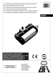
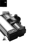
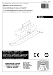
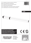
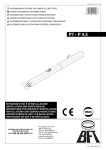
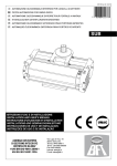
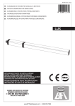
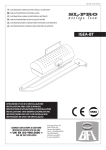
D811036 ver. 04 18-07-06 I AUTOMAZIONE OLEODINAMICA INTERRATA PER CANCELLI A BATTENTE GB PISTON AUTOMATIONS FOR SWING GATES F AUTOMATISME OLÉODYNAMIQUE ENTERRÉ POUR PORTAILS A VANTAUX D HYDRAULISCHER UNTERFLURDREHTORANTRIEB E AUTOMATISMO OLEODINÁMICO SOTERRADO PARA PORTONES BATIENTES P AUTOMAÇÃO ÓLEODINÂMICA ENTERRADA PARA PORTÕES DE BATENTE 8 027908 1 1 1 7 7 7 SUB ISTRUZIONI D’USO E DI INSTALLAZIONE INSTALLATION AND USER’S MANUAL INSTRUCTIONS D’UTILISATION ET D’INSTALLATION INSTALLATIONS-UND GEBRAUCHSANLEITUNG INSTRUCCIONES DE USO Y DE INSTALACION INSTRUÇÕES DE USO E DE INSTALAÇÃO Via Lago di Vico, 44 36015 Schio (VI) Tel.naz. 0445 696511 Tel.int. +39 0445 696533 Fax 0445 696522 Internet: www.bft.it E-mail: [email protected] D811036_04 INSTALLATION MANUAL Thank you for buying this product, our company is sure that you will be more than satisfied with its performance. This product is supplied with a “WARNINGS” leaflet and an “INSTRUCTION MANUAL”. These should both be read carefully as they provide important information about safety, installation, operation and maintenance. This product complies with recognised technical standards and safety regulations. We declare that this product is in conformity with the following European Directives: 89/336/EEC, 73/23/EEC and subsequent amendments. 1) GENERAL OUTLINE The SUB hydraulic controller provides the ideal solution for underground hinge-pivot installations, as it brilliantly solves aesthetic automation problems. The SUB actuator consists of a perfectly sealed single block, containing a hydraulic control unit and a jack, which provides a hidden underground installation without any hydraulic connections. The gate is kept closed by an electric lock, or by a hydraulic lock on the SUB versions supplied with it. The versions with slow-down functions avoid unpleasant slamming noise when the gate is brought to the final opening and closing stages. The pushing force can be adjusted with extreme precision by means of two by-pass valves which provide antisquash safety. The end-of-stroke operation is electronically set by a timer on the control panel. The emergency release, activated by the proper key supplied, can be easily reached after removing the appropriate cap found on the cover. 2) GENERAL SAFETY WARNING! An incorrect installation or improper use of the product can cause damage to persons, animals or things. • The “Warnings” leaflet and “Instruction booklet” supplied with this product should be read carefully as they provide important information about safety, installation, use and maintenance. • Scrap packing materials (plastic, cardboard, polystyrene etc) according to the provisions set out by current standards. Keep nylon or polystyrene bags out of children’s reach. • Keep the instructions together with the technical brochure for future reference. • This product was exclusively designed and manufactured for the use specified in the present documentation. Any other use not specified in this documentation could damage the product and be dangerous. • The Company declines all responsibility for any consequences resulting from improper use of the product, or use which is different from that expected and specified in the present documentation. • Do not install the product in explosive atmosphere. • The construction components of this product must comply with the following European Directives: 89/336/EEC, 73/23/EEC and subsequent amendments. As for all non-EEC countries, the above-mentioned standards as well as the current national standards should be respected in order to achieve a good safety level. • The Company declines all responsibility for any consequences resulting from failure to observe Good Technical Practice when constructing closing structures (door, gates etc.), as well as from any deformation which might occur during use. • The installation must comply with the provisions set out by the following European Directives: 89/336/EEC, 73/23/EEC and subsequent amendments. • Disconnect the electrical power supply before carrying out any work on the installation. Also disconnect any buffer batteries, if fitted. • Fit an omnipolar or magnetothermal switch on the mains power supply, having a contact opening distance equal to or greater than 3,5 mm. • Check that a differential switch with a 0.03A threshold is fitted just before the power supply mains. • Check that earthing is carried out correctly: connect all metal parts for closure (doors, gates etc.) and all system components provided with an earth terminal. • Fit all the safety devices (photocells, electric edges etc.) which are needed to protect the area from any danger caused by squashing, conveying and shearing. • Position at least one luminous signal indication device (blinker) where it can be easily seen, and fix a Warning sign to the structure. • The Company declines all responsibility with respect to the automation safety and correct operation when other manufacturers’ components are used. • Only use original parts for any maintenance or repair operation. • Do not modify the automation components, unless explicitly authorised by the company. • Instruct the product user about the control systems provided and the manual opening operation in case of emergency. ENGLISH • Do not allow persons or children to remain in the automation operation area. • Keep radio control or other control devices out of children’s reach, in order to avoid unintentional automation activation. • The user must avoid any attempt to carry out work or repair on the automation system, and always request the assistance of qualified personnel. • Anything which is not expressly provided for in the present instructions, is not allowed. • Installation must be carried out using the safety devices and controls prescribed by the EN 12978 Standard. • The motor cannot be installed on gates which incorporate doors (unless the motor drive can work with the door open). • Take care to avoid possible crushing, due to door movement, between the guided part and surrounding fixed parts. • If present, the holding device (hold-to-run control) must be fitted within sight of the guided part and well away from the operator working area. Unless it is activated by means of a key, it should be positioned at least 1.5 m high and should not be accessible to the public. • Make sure that persons are kept well away from the operator, in particular whenever the motor is used in «hold-to-run» mode. • Check that the range of temperature indicated is compatible with the place of installation. 3) MAIN AUTOMATION PARTS Single-block hydraulic actuator (fig.1) consisting of: M) 2-pole single-phase motor protected by thermal circuit-breaker. P) Hydraulic lobe pump. D) Distributor with adjustment valves. PC) Rack - pinion jack. Components supplied as standard: by-pass release and adjustment key, capacitor, grooved bush and instruction manual. WARNING: An actuator can be mounted on the left or right-hand side, as identified by looking at the gate from the inside (opening direction). An actuator can be recognised as left or right-handed by observing the position of release pivot “PST”. Fig.1 shows an actuator to be mounted on the left. 4) ACCESSORIES - CPS Bearing foundation case (provided for automation). - CID Non-bearing foundation case. - BSC Slide arm (for mounting to one side of the hinge-pivot). 5) TECHNICAL SPECIFICATIONS Single-phase power supply ..................................... 230V~ ±10% 50/60 Hz Motor revolutions .........................................................................2800 min-1 Output shaft revolutions . ...........................................................See Table 1 Absorbed power ................................................................................ 250 W Capacitor............................................................................................ 6.3 µF Absorbed current ................................................................................. 1.4 A Max torque ......................................................................................400 Nm Pressure ........................................................................3MPa (30 bar) max Pump capacity ...........................................................................See Table 1 Impact reaction ................................................................... Hydraulic clutch Manual manoeuvre . .................................................................Release key Max no. manoeuvres ............................................................. 500 / 24hours Thermal protection ........................................................................... 160 °C Environmental conditions .................................................. -10 °C to +60 C° Degree of protection ........................................................................... IP 67 Controller weight ....................SUB 220N (~22 kg) - SUB G 240N (~24 kg) Oil..................................................................................................IDROLUX Dimensions . .................................................................................. See fig.2 (*) Special voltages available on request. 6) ACTUATOR INSTALLATION 6.1) Preliminary checks Check that: - The leaf structure is sturdy and rigid. - The upper hinge is in working order and possibly adjustable. - A hole can be dug to lay the case under the hinge-pivot, or to one side of the hinge-pivot for slide arm installation. - The leaf ground stop plates are fitted. - Repair or replace all faulty or worn components. Fig.3 illustrates an exploded view of the installation. Automation reliability and safety are directly affected by the condition of the gate structure. 6.2) Electrical installation setup Set up the electrical installation as shown in fig.4, making reference to the current standards for electrical installations. Keep the mains supply connecSUB - Ver. 04 - 13 INSTALLATION MANUAL tions definitely separate from the service connections (photocells, electric edges, control devices, etc.). WARNING: For connection to the mains, use a multipolar cable of the type provided for by the previously mentioned standards (for example, if the cable is not protected, it must be at least equal to H07 RN-F, whereas if it is protected it must be at least equal to H07 VV-F with a 4x1.5 mm2 cross section). Connect the control and safety devices in compliance with the previously mentioned installation standards. Fig.4 shows the number of connections and the cross section for power supply cables about 100-m long; for greater lengths, calculate the cross section needed for the true automation load. 6.3) Main automation parts (Fig.4): I) Type-approved adequately rated omnipolar circuit-breaker with at least 3,5 mm contact opening, provided with protection against overloads and short circuits, suitable for cutting out automation from the mains. If not already installed, place a type-approved omnipolar circuit-breaker with a 0.03A threshold just before the automation system. Qr) Control panel and incorporated receiver. SPL) Preheating board for operation with temperature lower than 5°C (optional). S) Key selector. AL) Blinker with tuned antenna. M) Controller. E) Electric lock. Fte) External photocells (emitting section). Fre) External photocells (receiving section). Fti) Internal photocells with CF posts (emitting section). Fri) nternal photocells with CF posts (receiving section). T) 1-2-4 channel transmitter. RG58) Cable for antenna. D) Connector block. The connector block (fig. 6) must always be positioned higher than the motor. In fact, as the controller is perfectly sealed, the tank is made to breathe through the actuator supply cable. 6.4) Cementation of the foundation case (under the hinge-pivot) The case must be cemented under the hinge-pivot, keeping in mind that the actuator bearing shaft must be perfectly aligned to the leaf rotation axis. If the gate is provided with fixed hinges, disassemble it and remove the lower hinge. If the leaf is high enough from the ground and cannot be removed, proceed to supporting it by means of a shim placed between the ground and the leaf during installation. If the gate is provided with adjustable hinges, remove the lower hinge, loosen the upper one and move the leaf to the side. If the gate has been newly manufactured, fit an upper hinge which can be adjusted. - Dig a foundation hole having the dimensions shown in fig.5. - Provide a drainage pipe (fig.6) for rainwater in order to prevent stagnation inside the foundation case. Lay a raceway for the power supply cable as far as connector block “D” - Lay a strong foundation on the bottom (fig.5) where to bury the hooks of foundation case “P”. The dimensions for positioning plate “P” are defined in fig.5. Let the cement harden for the time needed. - Rest the actuator on base “P”, with its shaft perfectly aligned to the leaf axis (fig.7), and weld four angle bars “A” in correspondence with the four corners of the actuator centring base. The minimum dimension between the pillar and rotation shaft axis is shown in fig.6. - Assemble the foundation case by fixing its two half sections together by means of the screws supplied (fig.8), and fixing small plate “PI” to the back. Position the box around the actuator, so that small plate “PI” (fig. 8) fits around the shaft, and the edge of the box protrudes above the ground by about 10mm (fig.6). Position cover “CE” (fig.3) on the box and fix its corners with 2 screws. - Fill the rest of the hole with concrete. 6.5) Cementation of the foundation case (to one side of the hinge-pivot) Installation with slide arm (to one side of the hinge pivot). This is advisable when you want to avoid disassembling the existing gate leaf. Area “A” highlighted in fig.9 corresponds to a right-angled triangle having a side of approximately 200mm, where the actuator axis can be laid in order to allow the leaf to open by at least 90°. - The drive arm provides a distance between centres between grooved bush “B” and sliding roller “R” of up to 380mm. - Bush “B” must be welded to the drive arm with the leaf completely closed, the roller must be inserted into slide “S” taking into account the safety 14 - SUB - Ver. 04 degrees shown on small card “CA” (fig.11). For slowed-down versions, also take into account the slow-down degrees (fig.13). - Slide “S” (fig.9) can be welded or fixed with screws both underneath and to the side of the leaf. The position of the slide is to be identified by marking on the leaf the spots reached by sliding roller “R” both during closing and opening, Having identified the mid-point between the two markings made previously, align the mid-point of slide “S” and fix it tightly. If slide “S” is shorter than the distance between the two markings on the leaf, this type of installation is not possible. Keep in mind that, the nearer slide “S” is to the leaf rotation pivot, the greater will the leaf speed be. Having identified the actuator position, proceed to cementing the foundation case as described in paragraph 6.4. 7) BEARING FOUNDATION CASE Two bearing foundation case models - CPS for SUB and CPS G for SUB G (fig.10) - are available. Having installed the bearing case, the gate becomes operational even without mounting the actuator, which can be inserted later. In case of any maintenance needed, this type of case allows the actuator to be removed without disassembling the gate leaf. Should the CPS mod. bearing foundation case be used, refer to the respective manual for the positioning procedure. 8) LEAF MOUNTING With the actuator in its final position, proceed as follows. - Prepare a U-shaped shoe (fig.3) where the leaf is to be inserted and then fastened in its correct position by welding small plate “PS” to it. - Position grooved bush “B” in the actuator shaft. - Temporarily fasten the shoe to the leaf: mount the leaf in its completely closed position, placed over the actuator shaft and perfectly aligned to the rotation axis. - Before welding bush “B” to the U-shaped shoe, the right fixing point must be found. To determine the correct point, proceed as described below. WARNING: Do not weld bush “B” directly to the leaf. Do not weld the grooved bush to the actuator output shaft. 8.1) Version without slow-down function -Release the jack with key “CS” supplied, in the way shown in fig.18. -With the help of pliers, completely rotate the output shaft in the direction of gate closing along its entire stroke. -Arrange small card “CA” (fig.11) by positioning point “M” in correspondence with the arrow in the casting. -Rotate the shaft and bring point “G” (right-r.h. or left-l.h.) in correspondence with the arrow. -Protect the actuator from any metal spots during the subsequent welding phase. -The bush can now be welded to the shoe with the leaf mounted in the gate closed and stopped position. Disassemble the shoe to weld bush “B” all the way around its circumference. -Any small defects in levelling foundation plate “P” can be corrected by means of adjustment dowels “GR” (fig.3). -Place the gate stop on opening in the required position; however, the gate stop must maintain an extra rotation of at least 5° for safety, in order to prevent the rack from reaching its end of travel. NOTE: The rotation degrees of the SUB R versions are highlighted in fig. 12; in the case of versions without slow-down function, consider the slow-down angles (25°+25°) as normal speed. For the SUB G versions, take into account a total rotation of 185°. For effective 180° openings, the safety margin is 2.5° both on closing and on opening. 8.2) Version with slow-down function The versions provided with slow-down function need particular attention in identifying the fixing point of grooved bush “B” (fig.3). It is advisable to use the actuator in a symmetrical way; fig.12 shows the 130 degrees of total rotation of an ordinary actuator, divided into the various phases. By way of example, fig.13 shows the correct operation method for an actuator carrying out a leaf opening manoeuvre of 90°, that is 20°+ 20° for safety, 70° for normal stroke and 10°+ 10° for slow-down. In order to obtain the angles described, use small card “CA” on the “SUB R mod.” side (fig.11). WARNING: For effective opening manoeuvres of less than 90°, slow-down cannot be obtained in both directions.You need to decide beforehand whether to have slow-down on closing or opening, taking into account that slow-down begins to happen in the last 25°- 30° of shaft rotation, both on opening and closing (fig.14). Having determined the correct angle for fixing the grooved bush, fix it in the way described in paragraphs 8 - 8.1. NOTE: For the SUB GR versions, take into account a total rotation of 185°, out of which: 2.5°+ 2.5° for safety, 25°+ 25° for slow-down and 125° for stroke at normal speed. This provides a maximum rotation of 180°. D811036_04 ENGLISH D811036_04 INSTALLATION MANUAL 8.3) Slow-down adjustment (R versions only) Slow-down adjustment screws “VR” are highlighted in fig.15, and can be adjusted by means of a 3-mm Allen wrench. This must be turned clockwise to make the movement slower and anticlockwise to make is less slow. Adjust the slow-down speed so as to prevent the leaf from slamming when it stops. 8.4) Installation with slide arm (to one side of the hinge-pivot) This type of installation is illustrated in fig.9.The installation method is described in paragraph 6.5. Furthermore, the actuator support base must be tightly secured to the foundation base by means of screws, and not just fastened by the four angle bars as in the case of installation under the hinge-pivot. 9) STOP PLATES The use of ground stop plates “F” (fig.20) is compulsory both on opening and closing. The stop plates must lock the leaf while maintaining a safety extra-stroke of 5° at least (fig.12). 10) LEAF PHASE DIFFERENCE In the case where the leaves overlap during the closing manoeuvre, the phase difference on closing is set by means of the appropriate trimmer included in the electronic control unit. The motor of the delayed leaf must be connected to the terminals of the control unit, which are identified by the “Mr” symbol as illustrated in the control unit wiring diagram. 11) ELECTRIC LOCK FITTING This is only needed for models without hydraulic lock on closing (Table 1). The EBP mod. electric lock (fig.16) consists of a continuous- service electromagnet hooked to the ground. This device remains energised during the whole gearmotor operation time, allowing catch “D” to reach the closing stop point without opposing any resistance; this factor allows the pushing load to be reduced on closing, thus improving antisquash safety. 12) PUSHING FORCE ADJUSTMENT (Fig.1) This is obtained by means of two valves, marked by the writing “close” and “open” respectively, used to adjust the pushing force on closing and opening. If the valves are turned towards the “+” sign the force is increased, if they are turned towards the “-” sign it is decreased. To obtain good antisquash safety, the pushing force must be slightly greater than that needed to move the leaf, both on closing and opening; however, the force, measured at the leaf edge, must not exceed the limits set out by the current national standards. The actuator is not provided with electrical limit switches. Therefore the motors are switched off at the end of the operation time set in the control unit. Such operation time must exceed by about 2-3 seconds the moment where the leaves meet the ground stop plates. For this reason as well as for safety reasons, under no circumstances must the by-pass valves be completely closed. 13) MANUAL OPENING In case of emergency, for instance when there is no power available, the gate must be opened by hand. 13.1) Versions without hydraulic locks (electric lock) As these models are irreversible, in order to move the gate by hand you only need to open the electric lock by means of the appropriate key, and push the leaves with a force strong enough to win that adjusted with the by-pass valves (approximately 15 kg/150N). In order to make the manoeuvre easier, it may also be helpful to activate the hydraulic lock in the way described below. 13.2) Versions with hydraulic locks (Fig.17) - Unscrew cap “T” which is found on the cover of each actuator (usually on the inside). - Insert the release key supplied in triangular release pivot PST and rotate it anticlockwise by a few turns (CS in fig.18). - Push the leaf by hand at a speed similar to that of motorised operation. - To restore motorised operation, turn the key clockwise until it is completely tightened, screw the release cap onto the cover and put the key in a place which is known to all users. NOTE: In order to avoid oxidation of the release device, it is helpful to fill its triangular seat with grease. 14) AUTOMATION CHECK Before finally making the automation fully operative, carefully carry out the following procedure: - Check that all components are tightly secured. - Check the correct functioning of all safety devices (photocells, pneumatic edge etc.). ENGLISH - Check the emergency manoeuvre command. - Check the opening and closing operations with the control devices in use. - Check the standard (or customised) electronic function logic in the control unit. 15) AUTOMATION OPERATION As automation can be remotely controlled by means of a radio control or start button, it is essential to frequently check that all safety devices are perfectly efficient. In case of any operational malfunction, take immediate action and request the assistance of qualified personnel. It is recommended to keep children at a safe distance from the automation field of action. 16) CONTROL The automation system is used to obtain motorised gate opening and closing. There are different types of control (manual, radio, magnetic badge access control, etc.) depending on the installation requirements and characteristics. For the various control systems, see the relevant instructions. All automation users must be instructed on proper control and use. 17) MAINTENANCE All maintenance on the controller must be performed with the systems power supply shut off. Check periodically for oil leaks.When topping-up the oil, always use oil of the same type (see data table) and proceed as follows: a) Remove the cap “P” (fig.3). b) Top-up with oil until it reaches 1.5 mm on the oil cap hole. c) Reassemble all of the unit. ATTENTION: The oil of each actuator must be replaced completely every two years. Only use oil of the same type (see data table). - Check the safety devices of the automation. - When any operational malfunction is not resolved, disconnect the power supply from the system and request the assistance of qualified personnel. - If the leaves move jerkily, or if excessive noise is noticed during manoeuvring, this could be due to air being trapped in the hydraulic circuit, and therefore a bleed operation may be required. 17.1) Oil bleed NOTE: The actuator is supplied without air in the hydraulic circuit. If a bleed operation is required, proceed as described below. a) Remove the cover from the actuator. b) Activate the opening command and loosen the bleed screw (S) for opening (fig.19-20) during leaf movement. c) Let the air out until non-emulsified oil appears (if possible, try to prevent the oil leaking out of the bleed screw from falling into the foundation case). d) Tighten the bleed screw before the actuator runs out of operation time. e) Activate the closing command and loosen the bleed screw for closing (which can be seen in fig.20) during leaf movement. f) Let the air out until non-emulsified oil appears. g) Tighten the bleed screw before the actuator operation time runs out. h) Repeat this operation several times for both bleed screws. i) Restore the oil level, checking that it just reaches below cap “O” (fig.19). Top up with IDROLUX oil of the same type. 18) NOISE LEVEL The aerial noise level produced by the gearmotor under normal operating conditions is constant and does not exceed 70 dB (A). 19) SCRAPPING Materials must be disposed of in conformity with the current regulations. In case of scrapping, the automation components do not entail any particular risks or danger. In case of recovered materials, these should be sorted out by type (electrical components, copper, aluminium, plastic etc.). 20) DISMANTLING When the automation system is disassembled to be reassembled on another site, proceed as follows: - Disconnect the power supply and the entire electrical installation. - Remove the gearmotor from its fixing base. - Disassemble the control panel, if separate, and all the installation components. - In the case where some of the components cannot be removed or are damaged, they must be replaced. 21) MALFUNCTION: CAUSES and REMEDIES When any operational malfunction is found, and not resolved, disconnect the power supply from the system and request the assistance of qualified personnel (installer). When automation is out of order, activate the manual release to allow opening and closing manoeuvres to be carried out by hand. SUB - Ver. 04 - 15 ENGLISH D811036_04 INSTALLATION MANUAL 21.1) The gate does not open. The motor does not turn. 1) Check that the photocells or electric edges are not dirty, or engaged, or not aligned. Proceed accordingly. 2) Check that the electronic equipment is correctly supplied with power. Check the integrity of the fuses. 3) Check that the functions are correct by means of the control unit diagnosing leds (see relevant instructions). Identify any causes for faults. If the leds show a persistent start command, check that no radio controls, start buttons or other control devices keep the start contact activated (closed). 4) If the control unit does not work, it must be replaced. Should the checks listed above be satisfactory, replace the actuator. 21.2) The gate does not open. The actuator vibrates but there is no movement. 1) The manual release was left engaged. Reset motorised operation. Should an electric lock be fitted, check that it opens correctly after the start command. 2) Check that the capacitor is connected to the motor drive terminals. 3) Check that the motor common (light blue wire) is properly connected. 4) Disconnect and reconnect the power supply to the system. The first start command must open. Should the actuator close, reverse the respective drive connections to the actuator. 5) Help the leaf to open by hand. If the leaf opens, check if there are any mechanical problems with the leaf or, if necessary, adjust the by-pass valves as described in the relevant item 12. Should the checks listed above be satisfactory, replace the actuator. WARNINGS Correct controller operation is only ensured when the data contained in the present manual are observed. The company is not to be held responsible for any damage resulting from failure to observe the installation standards and the instructions contained in the present manual. The descriptions and illustrations contained in the present manual are not binding. The Company reserves the right to make any alterations deemed appropriate for the technical, manufacturing and commercial improvement of the product, while leaving the essential product features unchanged, at any time and without undertaking to update the present publication. TABLE 1 Mod. Block type Pump flow rate l/min Opening angle (degrees) Max. leaf length (mt) Max. leaf weight (kg) Speed (degrees/sec.) SUB EL SUB SUB R SUB E SUB ER SUB G SUB GR SUB GE SUB GER electric lock hydraulic blocks hydraulic blocks electric lock electric lock hydraulic blocks hydraulic blocks electric lock electric lock 0.4 (V0) 0.6 (V1) 0.9 (V2) 0.6 (V1) 0.9 (V2) 0.6 (V1) 0.9 (V2) 0.6 (V1) 0.9 (V2) 130° 130° 130° 130° 130° 180° 180° 180° 180° 3.5 1,8 1,8 2,5 2,5 1,8 1,8 2,5 2,5 8000N (~800 Kg) 8000N (~800 Kg) 8000N (~800 Kg) 8000N (~800 Kg) 8000N (~800 Kg) 8000N (~800 Kg) 8000N (~800 Kg) 8000N (~800 Kg) 8000N (~800 Kg) 16 - SUB - Ver. 04 3,9° 5,4° 9° 5,4° 9° 5,4° 9° 5,4° 9° D811036_04 Fig. 1 C PC OPEN CLOSE OPEN CLOSE PST P D M Fig. 2 Fig. 3 65 0 40 290 B SU PS G UB 0S 47 S B S CS CE MS M 0 20 GR P 60 A ~ 120 B 32 0 0 46 SU 0 53 B SU P 152 ÷ 158 125 40 B G SUB - Ver. 04 - 33 D811036_04 Fig. 4 AL Fre D S 2 2 m m 2x1 mm 2 4x1 m .5m 4x1 M Fti 3X1m RG5 8 Q R 2X1. Fte E CF m2 5mm2 2x1m m2 M D I 2X1 .5m m2 LINE 2 m .5m 4x1 T Fri m 4x1 3x1. 5mm 2 m CF Fig. 5 Fig. 6 P 110 10 min. 60mm mi 10 n. 60 = = 35 0 34 - SUB - Ver. 04 0 46 B 550 U G S B SU min. 50mm D 2 D811036_04 Fig. 7 Fig. 8 V PI A A P A CP Fig. 9 0 20 A 50 R S 20 0 Fig. 10 SUB - Ver. 04 - 35 D811036_04 Fig. 11 5° 5° G GM CA Fig. 12 - 13 - 14 25° 20° 10° 20° 10° 90° SUB 70° SUBG 125° 80° CLOSE SUB 5° SUBG 2,5° 70° 70° 10° OPEN 25° 25° 20° 5° 12 SUB 5° SUBG 2,5° 13 14 Fig. 15 VR Vite di regolazione Adjustment screw Vis de réglage Stellschraube Tornillo de regulación Parafuso de regulação 36 - SUB - Ver. 04 D811036_04 Fig. 17 Fig. 16 OPEN D Fig. 18 Fig. 19 O CS CLOSE OPEN S Fig. 20 1 • SFIATO APERTURA 1 • OPENING BREATHER 1 • PURGE OUVERTURE 1 • ENTLÜFTUNG ÖFFNUNG 1 • PURGADOR APERTURA 1 • SANGRIA DE ABERTURA 1 S 1 F SX 2 • SFIATO CHIUSURA 2 • CLOSING BREATHER 2 • PURGE FERMETURE 2 • ENTLÜFTUNG SCHLIEßUNG 2 • PURGADOR CIERRE 2 • SANGRIA DE FECHO F DX 2 S 2 F SUB - Ver. 04 - 37 D811036_04 38 - SUB - Ver. 04 D811036_04 SUB - Ver. 04 - 39