1
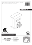
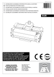
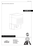
D811290 ver. 02 14-03-02 I AUTOMAZIONE OLEODINAMICA INTERRATA PER CANCELLI A BATTENTE GB PISTON AUTOMATIONS FOR SWING GATES 8 027908 171528 SUB- ISTRUZIONI D'USO E DI INSTALLAZIONE INSTALLATION AND USER'S MANUAL Via Lago di Vico, 44 36015 Schio (VI) Tel.naz. 0445 696511 Tel.int. +39 0445 696533 Fax 0445 696522 Internet: www.bft.it E-mail: [email protected] D811290_02 2 - SUB-UL - Ver. 02 D811290_02 MANUALE D’USO ITALIANO Nel ringraziarVi per la preferenza accordata a questo prodotto, la ditta è certa che da esso otterrete le prestazioni necessarie al Vostro uso. Leggete attentamente l’opuscolo “AVVERTENZE” ed il “LIBRETTO ISTRUZIONI” che accompagnano questo prodotto, in quanto forniscono importanti indicazioni riguardanti la sicurezza, l’installazione, l’uso e la manutenzione. Questo prodotto risponde alle norme riconosciute della tecnica e delle disposizioni relative alla sicurezza. Confermiamo che è conforme alle seguenti norme: CAN/CSA-C22.2 No. 247-92 UL Std. No. 325 (Certificato 1002906 in data 16 ottobre 2000). 1) GENERALITÀ L’operatore oleodinamico SUB è la soluzione ideale per applicazioni interrate sottocardine. Risolve brillantemente i problemi di estetica dell’automazione. L’attuatore SUB è realizzato con un unico monoblocco a tenuta stagna contenente la centralina idraulica - martinetto, che permette di ottenere un’installazione completamente interrata e priva di qualsiasi collegamento idraulico. La chiusura del cancello è mantenuta da un’elettroserratura oppure dal blocco idraulico nelle versioni SUB munite di tale dispositivo. Le versioni dotate di rallentamenti permettono un accostamento in apertura e chiusura senza fastidiosi sbattimenti. La forza di spinta si regola con estrema precisione mediante due valvole by-pass che costituiscono la sicurezza antischiacciamento. Il funzionamento a fine corsa è regolato elettronicamente nel quadro di comando mediante temporizzatore. Rimuovendo un apposito tappo sulla copertura si può accedere facilmente allo sblocco d’emergenza, che si attiva con l’apposita chiave in dotazione. 2) PARTI PRINCIPALI DELL’AUTOMAZIONE Attuatore oleodinamico monoblocco (fig.1) costituito da: M) Motore monofase 2 poli protetto da disgiuntore termico. P) Pompa idraulica a lobi. D) Distributore con valvole di regolazione. PC) Martinetto - cremagliera - pignone. Componenti in dotazione: chiave di sblocco e regolazione by-pass - condensatore - boccola scanalata - manuale istruzione. ATTENZIONE: L’attuatore può essere destro o sinistro e per convenzione si osserva il cancello dal lato interno (verso di apertura). L’attuatore destro o sinistro, è identificabile dalla posizione del perno di sblocco “PST”. In fig.1 è rappresentato un attuatore sinistro. 3) ACCESSORI - Cassa di fondazione portante CPS (predispone all’automazione). - Cassa di fondazione non portante CID. - Braccio a slitta BSC (per montaggio fuoricardine). 4) APERTURA MANUALE Nei casi di emergenza, per esempio in mancanza di energia elettrica, si rende necessaria l’apertura manuale del cancello. 5) USO DELL’AUTOMAZIONE Poiché l’automazione può essere comandata a distanza mediante radiocomando o pulsante di Start, è indispensabile controllare frequentemente la perfetta efficienza di tutti i dispositivi di sicurezza. Per qualsiasi anomalia di funzionamento, intervenire rapidamente avvalendosi di personale qualificato. Si raccomanda di tenere i bambini a debita distanza dal raggio d’azione dell’automazione. 6) MANUTENZIONE ATTENZIONE: Ogni due anni sostituire completamente l’olio di ogni attuatore. L’olio deve essere assolutamente dello stesso tipo (IDROLUX). 7) DEMOLIZIONE L’eliminazione dei materiali va fatta rispettando le norme vigenti. Nel caso di demolizione dell’automazione non esistono particolari pericoli o rischi derivanti dall’automazione stessa. È opportuno, in caso di recupero dei materiali, che vengano separati per tipologia (parti elettriche - rame - alluminio - plastica - ecc.). 8) SMANTELLAMENTO Nel caso l’automazione venga smontata per essere poi rimontata in altro sito bisogna: - Togliere l’alimentazione e scollegare tutto l’impianto elettrico. - Togliere il motoriduttore dalla base di fissaggio. - Smontare il quadro di comando se separato e tutti i componenti dell’installazione. - Nel caso alcuni componenti non possano essere rimossi o risultino danneggiati, provvedere alla loro sostituzione. 9) MALFUNZIONAMENTO. CAUSE e RIMEDI Per qualsiasi anomalia di funzionamento non risolta, togliere l’alimentazione al sistema e chiedere l’intervento di personale qualificato (installatore). Nel periodo di fuori servizio, attivare lo sblocco manuale per consentire l’apertura e la chiusura manuale. Fig. 1 C PC OPEN CLOSE OPEN CLOSE PST D P M SUB-UL - Ver. 02- 3 USER’S MANUAL Thank you for buying this product, our company is sure that you will be more than satisfied with its performance. This product is supplied with a “WARNINGS” leaflet and an “INSTRUCTION MANUAL”. These should both be read carefully as they provide important information about safety, installation, operation and maintenance. This product complies with recognised technical standards and safety regulations. We declare that this product is in conformity with the following directives: CAN/CSA-C22.2 No. 247-92 UL Std. No. 325 (Certificate: 1002906 Date Issued: October 16, 2000). 1) GENERAL OUTLINE The SUB hydraulic controller provides the ideal solution for underground hinge-pivot installations, as it brilliantly solves aesthetic automation problems. The SUB actuator consists of a perfectly sealed single block, containing a hydraulic control unit and a jack, which provides a hidden underground installation without any hydraulic connections. The gate is kept closed by an electric lock, or by a hydraulic lock on the SUB versions supplied with it. The versions with slow-down functions avoid unpleasant slamming noise when the gate is brought to the final opening and closing stages. The pushing force can be adjusted with extreme precision by means of two by-pass valves which provide antisquash safety. The end-of-stroke operation is electronically set by a timer on the control panel. The emergency release, activated by the proper key supplied, can be easily reached after removing the appropriate cap found on the cover. 2) MAIN AUTOMATION PARTS Single-block hydraulic actuator (fig.1) consisting of: M) 2-pole single-phase motor protected by thermal circuit-breaker. P) Hydraulic lobe pump. D) Distributor with adjustment valves. PC) Rack - pinion jack. Components supplied as standard: by-pass release and adjustment key, capacitor, grooved bush and instruction manual. WARNING: An actuator can be mounted on the left or right-hand side, as identified by looking at the gate from the inside (opening direction). An actuator can be recognised as left or right-handed by observing the position of release pivot “PST”. Fig.1 shows an actuator to be mounted on the left. 3) ACCESSORIES - CPS Bearing foundation case (provided for automation). - CID Non-bearing foundation case. - BSC Slide arm (for mounting to one side of the hinge-pivot). 4) MANUAL OPENING In case of emergency, for instance when there is no power available, the gate must be opened by hand. 5) AUTOMATION OPERATION As automation can be remotely controlled by means of a radio control or start button, it is essential to frequently check that all safety devices are perfectly efficient. In case of any operational malfunction, take immediate action and request the assistance of qualified personnel. It is recommended to keep children at a safe distance from the automation field of action. 6) MAINTENANCE ATTENTION: The oil of each actuator must be replaced completely every two years. Only use oil of the same type (IDROLUX). 7) SCRAPPING Materials must be disposed of in conformity with the current regulations. In case of scrapping, the automation components do not entail any particular risks or danger. In case of recovered materials, these should be sorted out by type (electrical components, copper, aluminium, plastic etc.). 8) DISMANTLING When the automation system is disassembled to be reassembled on another site, proceed as follows: - Disconnect the power supply and the entire electrical installation. - Remove the gearmotor from its fixing base. - Disassemble the control panel, if separate, and all the installation components. - In the case where some of the components cannot be removed or are damaged, they must be replaced. 9) MALFUNCTION: CAUSES and REMEDIES When any operational malfunction is found, and not resolved, disconnect the power supply from the system and request the assistance of qualified personnel (installer). When automation is out of order, activate the manual release to allow opening and closing manoeuvres to be carried out by hand. Fig. 1 C PC OPEN CLOSE OPEN CLOSE PST D 4 - SUB-UL - Ver. 02 P M D811290_02 ENGLISH D811290_02 MANUALE PER L’INSTALLAZIONE Nel ringraziarVi per la preferenza accordata a questo prodotto, la ditta è certa che da esso otterrete le prestazioni necessarie al Vostro uso. Leggete attentamente l’opuscolo “AVVERTENZE” ed il “LIBRETTO ISTRUZIONI” che accompagnano questo prodotto, in quanto forniscono importanti indicazioni riguardanti la sicurezza, l’installazione, l’uso e la manutenzione. Questo prodotto risponde alle norme riconosciute della tecnica e delle disposizioni relative alla sicurezza. Confermiamo che è conforme alle seguenti norme: CAN/CSA-C22.2 No. 247-92 UL Std. No. 325 (Certificato 1002906 in data 16 ottobre 2000). • • • • • 1) GENERALITÀ L’operatore oleodinamico SUB è la soluzione ideale per applicazioni interrate sottocardine. Risolve brillantemente i problemi di estetica dell’automazione. L’attuatore SUB è realizzato con un unico monoblocco a tenuta stagna contenente la centralina idraulica - martinetto, che permette di ottenere un’installazione completamente interrata e priva di qualsiasi collegamento idraulico. La chiusura del cancello è mantenuta da un’elettroserratura oppure dal blocco idraulico nelle versioni SUB munite di tale dispositivo. Le versioni dotate di rallentamenti permettono un accostamento in apertura e chiusura senza fastidiosi sbattimenti. La forza di spinta si regola con estrema precisione mediante due valvole by-pass che costituiscono la sicurezza antischiacciamento. Il funzionamento a fine corsa è regolato elettronicamente nel quadro di comando mediante temporizzatore. Rimuovendo un apposito tappo sulla copertura si può accedere facilmente allo sblocco d’emergenza, che si attiva con l’apposita chiave in dotazione. 2) SICUREZZA GENERALE ATTENZIONE! Una installazione errata o un uso improprio del prodotto, può creare danni a persone, animali o cose. • Leggete attentamente l’opuscolo ”Avvertenze” ed il ”Libretto istruzioni” che accompagnano questo prodotto, in quanto forniscono Importanti indicazioni riguardanti la sicurezza, l’installazione, l’uso e la manutenzione. • Smaltire i materiali di imballo (plastica, cartone, polistirolo, ecc.) secondo quanto previsto dalle norme vigenti. Non lasciare buste di nylon e polistirolo a portata dei bambini. • Conservare le istruzioni per allegarle al fascicolo tecnico e per consultazioni future. • Questo prodotto è stato progettato e costruito esclusivamente per l’utilizzo indicato in questa documentazione. Usi non indicati in questa documentazione potrebbero essere fonte di danni al prodotto e fonte di pericolo. • La Ditta declina qualsiasi responsabilità derivante dall’uso improprio o diverso da quello per cui è destinato ed indicato nella presente documentazione. • Non installare il prodotto in atmosfera esplosiva. • La Ditta declina qualsiasi responsabilità dall’inosservanza della Buona Tecnica nella costruzione delle chiusure (porte, cancelli, ecc.), nonché dalle deformazioni che potrebbero verificarsi durante l’uso. • Togliere l’alimentazione elettrica, prima di qualsiasi intervento sull’impianto. Scollegare anche eventuali batterie tampone se presenti. • Prevedere sulla rete di alimentazione dell’automazione, un interruttore o un magnetotermico onnipolare con distanza di apertura dei contatti uguale o superiore a 0.11 in (3mm). • Verificare che a monte della rete di alimentazione, vi sia un interruttore differenziale con soglia da 0.03A. • Verificare se l’impianto di terra è realizzato correttamente: collegare tutte le parti metalliche della chiusura (porte, cancelli, ecc.) e tutti i componenti dell’impianto provvisti di morsetto di terra. • Applicare tutti i dispositivi di sicurezza (fotocellule, coste sensibili, ecc.) necessari a proteggere l’area da pericoli di schiacciamento, convogliamento, cesoiamento, secondo ed in conformità alle direttive e norme tecniche applicabili. • Applicare almeno un dispositivo di segnalazione luminosa (lampeggiante) in posizione visibile, fissare alla struttura un cartello di Attenzione. • La Ditta declina ogni responsabilità ai fini della sicurezza e del buon funzionamento dell’automazione se vengono impiegati componenti di altri produttori. • Usare esclusivamente parti originali per qualsiasi manutenzione o • ITALIANO riparazione. Non eseguire alcuna modifica ai componenti dell’automazione se non espressamente autorizzata dalla Ditta. Istruire l’utilizzatore dell’impianto per quanto riguarda i sistemi di comando applicati e l’esecuzione dell’apertura manuale in caso di emergenza. Non permettere a persone e bambini di sostare nell’area d’azione dell’automazione. Non lasciare radiocomandi o altri dispositivi di comando alla portata dei bambini onde evitare azionamenti involontari dell’automazione. L’utilizzatore deve evitare qualsiasi tentativo di intervento o riparazione dell’automazione e rivolgersi solo a personale qualificato. Tutto quello che non è espressamente previsto in queste istruzioni, non è permesso. INSTALLARE L’APRICANCELLO SOLO QUANDO: • L’attuatore risulta idoneo per la tipologia costruttiva del cancello e per la classe di utilizzo del cancello. • Tutti i punti di schiacciamento evidenti sono protetti o schermati. • L’apricancello è concepito per essere installato solo su cancelli utilizzati per il passaggio di veicoli. Per i pedoni devono essere previsti accessi separati. • Il cancello deve essere installato in una posizione tale da garantire una distanza sufficiente tra il cancello e le strutture adiacenti durante l’apertura e la chiusura, al fine di ridurre il rischio di intrappolamento. I cancelli a battente non potranno essere aperti in aree di pubblico accesso. • Il cancello deve essere installato correttamente e deve funzionare liberamente in entrambe le direzioni prima dell’installazione dell’apricancello. Non serrare eccessivamente la frizione dell’attuatore o la valvola di sfiato della pressione per rimediare ad un cancello danneggiato. IN CASO DI APRICANCELLI CON COMANDO UOMO PRESENTE: • I comandi dell’apricancello devono essere posizionati in modo tale che l’utilizzatore abbia una visuale completa dell’area del cancello quando il cancello è in movimento. • Dovrà essere posizionato vicino ai comandi un cartello recante la scritta “AVVERTENZA” dalle lettere alte almeno 6,4 mm. e la seguente dichiarazione: “ Il cancello in movimento è in grado di causare lesioni o morte - non azionate il cancello quando il percorso non è libero”. • Non dovranno essere utilizzati dispositivi di chiusura automatici (quali temporizzatori, rilevatori di spira o dispositivi similari). • Non dovrà essere collegato nessun altro dispositivo di attivazione. I comandi devono essere sufficientemente lontani dal cancello in modo che l’utente non possa venire a contatto con il cancello quando utilizza tali comandi. I comandi previsti per il resettaggio dell’attuatore dopo due attivazioni successive del dispositivo/i contro l’intrappolamento devono essere posizionati sulla linea visiva del cancello. I comandi esterni o facilmente accessibili dovranno essere dotati di protezione al fine di impedirne l’utilizzo non autorizzato. I segnali di avvertenza e i cartelli devono essere installati in una posizione visibile nell’area del cancello. IN CASO DI ATTUATORI CHE UTILIZZANO UN SENSORE CON RILEVAMENTO SENZA CONTATTO: • Leggere le istruzioni sul posizionamento dei sensori senza contatto per ogni tipo di applicazione. • Provvedere affinché venga ridotto al minimo il rischio di intervento di disturbi come quando, ad esempio, il veicolo fa scattare il sensore mentre il cancello è ancora in movimento. • Posizionare uno o più sensori senza contatto dove esiste il rischio di intrappolamento o ostruzione, ad esempio lungo il perimetro raggiunto dal cancello in movimento. IN CASO DI ATTUATORI CHE UTILIZZANO UN SENSORE CON RILEVAMENTO A CONTATTO (COSTA SENSIBILE O EQUIVALENTE): • Dovranno essere installati uno o più sensori di contatto sul punto di serraggio di cancelli verticali a cardine per passaggio veicolare. SUB-UL - Ver. 02- 5 • • MANUALE PER L’INSTALLAZIONE Dovrà essere installato un sensore con contatto a circuito permanente i cui cablaggi dovranno essere disposti in modo tale che la comunicazione tra il sensore e l’apricancello non sia soggetta a danni meccanici. Dovrà essere installato un sensore con contatto senza fili quale ad esempio un sensore che trasmette segnali di frequenze radio (RF) all’apricancello per le funzioni di protezione contro l’intrappolamento nei casi in cui la trasmissione dei segnali non sia ostacolata o impedita dalla struttura dell’edificio, dal paesaggio naturale o da ostacoli similari. Il sensore con contatto senza fili dovrà funzionare conformemente alle condizioni per l’utilizzo finale previste. IMPORTANTI PRESCRIZIONI DI SICUREZZA ATTENZIONE: al fine di ridurre il rischio di danni fisici o morte: • Leggere e osservare tutte le istruzioni. • Non permettere ai bambini di utilizzare o giocare con i comandi del cancello. Tenere il telecomando fuori dalla portata dei bambini. • Tenere lontani oggetti e persone dal cancello. NON E’ PERMESSO ATTRAVERSARE IL PERCORSO ESEGUITO DAL CANCELLO IN MOVIMENTO. • Controllare mensilmente il corretto funzionamento del cancello. Il cancello DEVE invertire marcia in caso di contatto con oggetti rigidi e deve fermarsi quando un oggetto attiva i sensori senza contatto. Dopo aver regolato la forza o il finecorsa, ricontrollare l’apricancello. La mancata regolazione e l’omissione del successivo controllo dell’apricancello possono aumentare il rischio di danni fisici e di morte. • Utilizzare lo sblocco di emergenza solo a cancello fermo. • ESEGUIRE UNA MANUTENZIONE REGOLARE DEL CANCELLO. Leggere il manuale dell’utilizzatore. Eventuali riparazioni alle parti meccaniche del cancello devono essere eseguite da personale qualificato. • L’entrata è riservata ai veicoli. Prevedere un’entrata separata per i pedoni. • Conservare le presenti istruzioni. 3) PARTI PRINCIPALI DELL’AUTOMAZIONE Attuatore oleodinamico monoblocco (fig.1) costituito da : M) Motore monofase 2 poli protetto da disgiuntore termico. P) Pompa idraulica a lobi. D) Distributore con valvole di regolazione. PC) Martinetto - cremagliera - pignone. Componenti in dotazione: chiave di sblocco e regolazione by-pass condensatore - boccola scanalata - manuale istruzione. ATTENZIONE: L’attuatore può essere destro o sinistro e per convenzione si osserva il cancello dal lato interno (verso di apertura). L’attuatore destro o sinistro, è identificabile dalla posizione del perno di sblocco “PST”. In fig.1 è rappresentato un attuatore sinistro. 4) ACCESSORI - Cassa di fondazione portante CPS (predispone all’automazione). - Cassa di fondazione non portante CID. - Braccio a slitta BSC (per montaggio fuoricardine). 5) DATI TECNICI Alimentazione monofase ....................................... 120V~ ±10% 50/60 Hz Giri motore ................................................................................. 2800 min-1 Giri albero uscita ............................................................. Vedere Tabella1 Potenza assorbita ............................................................................ 250 W Condensatore ................................................................................... 6.3 µF Corrente assorbita ............................................................................. 1.4 A Coppia max .................................................. 400 Nm..............295.02 lbf/ft Pressione .................................... max 3MPa (30 bar)..........62656.3 lb/ft2 Portata pompa ................................................................. Vedere Tabella1 Reazione all’urto ............................................................. Frizione idraulica Manovra manuale .......................................................... Chiave di sblocco Max n° manovre ......................................................................... 24ore 500 Protezione termica ...................................... 160° C........................320° F Condizioni ambiente ................ da -10 °C a +60° C..........da 14° a 140° F Grado di protezione ........................................................................... IP 67 Peso operatore: SUB 220N ................................................... (~22 kg)...................~48.50 lb 6 - SUB-UL - Ver. 02 SUB G 240N ............................................... (~24 kg)...................~52.91 lb Olio .............................................................................................. IDROLUX Dimensioni ................................................................................... Vedi fig.2 (*) Tensioni speciali a richiesta. 6) INSTALLAZIONE DELL’ATTUATORE 6.1) Verifiche preliminari Controllare: - Che la struttura delle ante sia robusta e rigida. - Che la cerniera superiore sia in buono stato e possibilmente del tipo regolabile. - Che sia possibile eseguire lo scavo per l’interramento della cassa sotto il cardine oppure fuori cardine per applicazioni con braccio a slitta. - Che siano installate le battute d’arresto delle ante. - Sistemare o sostituire le parti difettose o usurate. In fig.3, è riportato un esploso dell’installazione. L’affidabilità e la sicurezza dell’automazione è direttamente influenzata dallo stato della struttura del cancello. 6.2) Predisposizione impianto elettrico Predisporre l’impianto elettrico come indicato in fig.4 facendo riferimento alle norme vigenti per gli impianti elettrici. Tenere nettamente separati i collegamenti di alimentazione di rete dai collegamenti di servizio (fotocellule, coste sensibili, dispositivi di comando ecc.). ATTENZIONE: Per il collegamento alla rete, utilizzare cavo multipolare del tipo previsto dalle normative (UL 1025). Realizzare i collegamenti dei dispositivi di comando e di sicurezza in armonia con le norme per l’impiantistica precedentemente citate. In fig.4 è riportato il numero di collegamenti e la sezione per una lunghezza dei conduttori di circa 100 metri; per lunghezze superiori, calcolare la sezione per il carico reale dell’automazione. 6.3) Componenti principali per una automazione sono (Fig.4): I) Interruttore onnipolare omologato di adeguata portata con apertura contatti di almeno 0.11 in (3mm) provvisto di protezione contro isovraccarichi ed i corti circuiti, atto a sezionare l’automazione dalla rete. Installare a monte dell'automazione, se non già presente, un interruttore onnipolare omologato con soglia 0,03A. Qr) Quadro comando e ricevente incorporata. SPL) Scheda di preriscaldamento per funzionamento a temperature inferiori ai 41°F (5°C) (optional). S) Selettore a chiave. AL) Lampeggiante con antenna accordata. M) Operatore. E) Elettroserratura. Fte) Fotocellule esterne (parte emittente). Fre) Fotocellule esterne (parte ricevente). Fti) Fotocellule interne con colonnine CF (parte emittente). Fri) Fotocellule interne con colonnine CF (parte ricevente). T) Trasmittente 1-2-4 canali. RG58) Cavo per antenna. D) Scatola di derivazione. La scatola di derivazione (fig.6) deve essere sempre posta in posizione elevata rispetto al motore. Infatti, essendo l’operatore stagno, lo sfiato del serbatoio avviene attraverso il cavo di alimentazione dell’attuatore. 6.4) Cementazione della cassa di fondazione (sotto cardine) Deve essere cementata in posizione sottocardine considerando che l’albero portante dell’attuatore deve risultare perfettamente allineato all’asse di rotazione dell’anta. Se il cancello è del tipo a cerniere fisse, rimuovere il cancello e togliere la cerniera inferiore. Se l’anta è sufficientemente alta dal suolo e non si può rimuovere, provvedere al suo sostegno tramite uno spessore tra suolo ed anta stessa durante la messa in opera. Se il cancello è del tipo a cerniere regolabili, togliere quella inferiore, allentare la cerniera superiore e spostare lateralmente l’anta. Se il cancello è di nuova realizzazione, prevedere una cerniera superiore del tipo regolabile. - Eseguire uno scavo di fondazione delle dimensioni indicate in fig.5. - Prevedere un tubo di scarico (fig.6) per l’acqua piovana in modo da evitare ristagni all’interno della cassa di fondazione. Predisporre la canaletta per il cavo di alimentazione fino alla vicina scatola di derivazione “D”. - Realizzare sul fondo, una solida fondazione (fig.5) dove annegare le D811290_02 ITALIANO D811290_02 MANUALE PER L’INSTALLAZIONE - - - zanche della piastra di fondazione “P”. Le quote di posizionamento della piastra “P” si determinano in fig.5. Lasciare rapprendere il cemento per il tempo necessario. Appoggiare l’attuatore sulla base “P” con l’albero perfettamente allineato all’asse dell’anta (fig.7) e saldare quattro angolari “A” in corrispondenza dei quattro angoli della base di centraggio dell’attuatore. La quota minima fra pilastro ed asse dell’albero di rotazione è rappresenta in fig.6. Comporre la cassa di fondazione fissando le due semiscatole con le viti in dotazione (fig.8), fissando la placchetta “PI” nella parte posteriore. Posizionare la scatola attorno all’attuatore in modo che la placchetta ”PI” (fig.8) contorni l’albero e che il bordo della scatola sporga dal pavimento di circa 0.39 in (10mm) (fig.6). Posizionare il coperchio ”CE” (fig.3) della scatola e fissarne gli angoli con 2 viti. Riempire con calcestruzzo lo scavo restante. 6.5) Cementazione della cassa di fondazione (fuoricardine) Installazione con braccio a slitta (fuoricardine). É consigliata quando si vuole evitare di smontare l’anta del cancello esistente. In fig.9 è evidenziata l’area “A”, corrispondente ad un triangolo rettangolo di circa 7.87 in (200mm) di lato, nella quale può giacere l’asse dell’attuatore per consentire una apertura dell’anta di almeno 90°. - Il braccio di comando permette un interasse fra boccola scanalata “B” e rullino di scorrimento “R” di 14.96 in (380mm) massimo. - La boccola “B” deve essere saldata al braccio di comando ad anta completamente chiusa, il rullino inserito nella slitta “S” e considerando i gradi di sicurezza riportati nel cartoncino “CA” (fig.11). Per le versioni rallentate, considerare anche i gradi di ralentamento (fig.13). - La slitta “S” (fig.9), può essere saldata o fissata con viti sia sotto che a fianco dell’anta. La posizione della slitta va individuata segnando sull’anta i punti dove arriva il rullino di scorrimento “R” sia in chiusura che in apertura. Individuata la mezzeria fra i due punti precedentemente segnati, allineare la mezzeria della slitta “S” e fissarla saldamente. Se la slitta “S” è più corta della distanza fra i due punti segnati nell”anta, non è possibile questo tipo di installazione. Tenere presente che, più la slitta “S” è vicina al perno di rotazione dell’anta, maggiore è la velocità dell’anta. Individuato il posizionamento dell’attuatore, procedere alla cementazione della cassa di fondazione come descritto al paragrafo 6.4. 7) CASSA DI FONDAZIONE PORTANTE É disponibile la cassa di fondazione portante mod. CPS per SUB e mod. CPS G per SUB G (fig.10). Installata la cassa portante, il cancello è operativo anche senza montare l’attuatore che può essere inserito successivamente. In caso di manutenzione, questo tipo di cassa consente di togliere l’attuatore senza smontare l’anta del cancello. Nel caso si usi la cassa di fondazione portante mod. CPS, per la procedura di posizionamento fare riferimento al rispettivo manuale). 8) MONTAGGIO DELL’ANTA - Con l’attuatore in posizione definitiva, procedere come segue. - Preparare una scarpetta ad “U” (fig.3) nella quale si incastra l’anta che poi verrà bloccata nella posizione corretta saldando la piastrina “PS”. - Posizionare la boccola “B” scanalata nell’albero dell’attuatore. - Bloccare provvisoriamente la scarpetta all’anta: montare l’anta in posizione di chiusura completa, posizionata sopra l’albero dell’attuatore e perfettamente allineata all’asse di rotazione. - Prima di saldare la boccola “B” alla scarpetta ad “U” realizzata, necessita trovare il giusto punto di fissaggio. Per determinare il punto corretto, procedere come segue. ATTENZIONE: Non saldare la boccola “B” direttamente all’anta. Non saldare la boccola scanalata all’albero di uscita dell’attuatore. 8.1) Versione senza rallentamento - Sbloccare il martinetto con la chiave “CS” in dotazione e nel modo indicato in fig.18. - Con l’aiuto di una pinza, ruotare completamente l’albero di uscita nel verso di chiusura del cancello per tutta la sua corsa. - Regolare il cartoncino “CA” (fig.11) posizionando il punto “M” in corrispondenza della freccia presente nella fusione. - Ruotare l’albero portando il punto “G” (destro-dx o sinistro-sx) in corrispondenza della freccia. - Proteggere l’attuatore dalle proiezioni di metallo durante la successiva ITALIANO fase di saldatura. È ora possibile saldare la boccola alla scarpetta con l’anta montata in posizione di chiusura ed in battuta d’arresto. Smontare la scarpetta per saldare completamente lungo tutta la sua circonferenza, la boccola “B”. - Eventuali piccoli difetti di messa in piano della piastra di fondazione “P”, possono essere corretti con i grani di regolazione “GR” (fig.3). - Posizionare la battuta d’arresto in apertura nella posizione desiderata; comunque, la battuta d’arresto deve mantenere una extrarotozione di almeno 5° di sicurezza per evitare che la cremagliera interna vada a finecorsa. NOTE: I gradi di rotazione delle versioni SUB R, sono evidenziati in fig.12; nel caso di versioni senza rallentamento, considerare gli angoli di rallentamento (25°+25°) come velocità normale. Per le versioni SUB G, va considerata una rotazione totale di 185°. Per aperture effettive di 180°, il margine di sicurezza è di 2.5° sia in chiusura che in apertura. - 8.2) Versione con rallentamenti Per le versioni con rallentamento necessita una particolare attenzione nell’individuare il punto di fissaggio della boccola scanalata “B” (fig.3). Si consiglia di utilizzare l’attuatore in modo simmetrico; in fig.12 sono rappresentati i 130 gradi di rotazione totale di un attuatore normale suddivisi nelle varie fasi. A titolo di esempio, in fig.13 è rappresentato il modo corretto di funzionamento di un attuatore che esegue una apertura di 90° dell’anta, ossia: 20°+ 20° di sicurezza, 70° di corsa normale, 10°+ 10° di rallentamento. Per realizzare gli angoli descritti, utilizzare il cartoncino “CA” dal lato “mod. SUB R” (fig.11). ATTENZIONE: Per aperture effettive, inferiori ai 90° non è possibile ottenere il rallentamento in entrambi i versi. Necessita decidere a priori se avere il rallentamento in chiusura o in apertura considerando che il rallentamento comincia ad agire negli ultimi 25°- 30° di rotazione dell’albero, sia in apertura che in chiusura (fig.14). Determinato l’angolo corretto per il fissaggio della boccola scanalata, per il fissaggio, eseguire quanto previsto al paragrafo 8 - 8.1 . NOTE: Per le versioni SUB GR, va considerata una rotazione totale di 185° di cui: 2.5°+ 2.5° di sicurezza, 25°+ 25° di rallentamento, 125° di corsa a velocità normale. Il tutto, consente un utilizzo max di 180°. 8.3) Regolazione rallentamento (solo versioni R) Le viti di regolazione del rallentamento “VR” sono evidenziate in fig.15 e si regolano utilizzando una chiave esagonale da 3mm. Ruotando in senso orario il moto è più rallentato, ruotando in senso antiorario è meno rallentato. Regolare la velocità di rallentamento in modo da evitare lo sbattimento dell’anta nelle battute d’arresto. 8.4) Installazione con braccio a slitta (fuori cardine) L’installazione è rappresentata in fig.9. Il modo di installazione è descritto al paragrafo 6.5. Inoltre, la base di appoggio dell’attuatore deve essere saldamente fissata con viti alla base di fondazione e non solamente incastrata nei quattro angolari come nell’installazione sottocardine. 9) BATTUTE D’ARRESTO É obbligatorio l’uso delle battute d’arresto al suolo “F” (fig.20) sia in apertura che in chiusura. Le battute d’arresto devono bloccare l’anta mantenendo una rotazione extra-corsa di sicurezza di almeno 5° (fig.12). 10) SFASAMENTO DELLE ANTE Nel caso di ante con sovrapposizione in chiusura, lo sfasamento in chiusura, viene regolato con l’apposito trimmer previsto nella centralina elettronica di comando. Il motore dell’anta in ritardo deve essere collegato ai morsetti della centralina identificati dal simbolo “Mr” rappresentati nello schema di collegamento della centralina. 11) APPLICAZIONE DELL’ELETTROSERRATURA É necessaria solo nei modelli senza blocco idraulico in chiusura (Tabella 1). L’elettroserratura mod. EBP (fig.16) è costituita da un elettromagnete a servizio continuo con aggancio al suolo. In questo dispositivo l’eccitazione rimane per tutto il tempo di lavoro del motoriduttore consentendo al dente di aggancio “D” di arrivare in battuta di chiusura sollevato senza opporre la minima resistenza; tale proprietà permette di diminuire il carica di spinta in chiusura migliorando la sicurezza antischiacciamento. SUB-UL - Ver. 02- 7 MANUALE PER L’INSTALLAZIONE 12) REGOLAZIONE DELLA FORZA DI SPINTA (Fig.1) È regolata da due valvole contraddistinte dalla scritta “close” e “open” rispettivamente per la regolazione della forza di spinta in chiusura ed in apertura. Ruotando le valvole verso il segno “+”, aumenta la forza trasmessa; ruotando le valvole verso il segno “-”, diminuisce. Per una buona sicurezza antischiacciamento, la forza di spinta deve essere di poco superiore a quella necessaria per muovere l’anta sia in chiusura che in apertura; la forza, misurata in punta all’anta, non deve comunque superare i limiti previsti dalle norme nazionali vigenti. L’attuatore è sprovvisto di finecorsa elettrici. Pertanto i motori si spengono quando è terminato il tempo di lavoro impostato nella centralina di comando. Tale tempo di lavoro, deve essere di circa 2-3 secondi superiore al momento in cui le ante incontrano le battute d’arresto al suolo. Per questo motivo e per motivi di sicurezza, in nessun caso si devono chiudere completamente le valvole dei by-pass. 13) APERTURA MANUALE Nei casi di emergenza, per esempio in mancanza di energia elettrica, si rende necessaria l’apertura manuale del cancello. 13.1) Versioni senza blocchi idraulici (elettroserratura) Essendo questi modelli reversibili, per la manovra manuale del cancello è sufficiente aprire l’elettroserratura con la relativa chiave e spingere le ante con una forza sufficiente a vincere quella regolata con i By-pass (circa 15 kg/150N). Per agevolare la manovra può essere utile attivare anche lo sblocco idraulico nel modo di seguito descritto. 13.2) Versioni con blocchi idraulici (Fig.17) - Svitare il tappo “T” presente nel coperchio di ogni attuatore (generalmente dal lato interno). - Inserire la chiave di sblocco in dotazione, nel perno sblocco triangolare PST e ruotare in senso antiorario per alcuni giri (fig.18 CS). - Spingere manualmente l’anta ad una velocità simile a quella motorizzata. - Per ripristinare il funzionamento motorizzato, girare la chiave in senso orario fino al completo serraggio, avvitare il tappo di sblocco al coperchio ,e riporre la chiave in luogo conosciuto agli utilizzatori. NOTE: per evitare eventuali ossidazioni del dispositivo di sblocco, risulta utile riempire la sede triangolare di grasso. 14) VERIFICA DELL’AUTOMAZIONE Prima di rendere definitivamente operativa l’automazione, controllare scrupolosamente quanto segue: - Verificare che tutti i componenti siano fissati saldamente. - Controllare il corretto funzionamento di tutti i dispositivi di sicurezza (fotocellule, costa pneumatica, ecc.). - Verificare il comando della manovra di emergenza. - Verificare l’operazione di apertura e chiusura con i dispositivi di comando applicati. - Verificare la logica elettronica di funzionamento normale (o personalizzata) nella centralina di comando. 15) USO DELL’AUTOMAZIONE Poiché l’automazione può essere comandata a distanza mediante radiocomando o pulsante di Start, è indispensabile controllare frequentemente la perfetta efficienza di tutti i dispositivi di sicurezza. Per qualsiasi anomalia di funzionamento, intervenire rapidamente avvalendosi di personale qualificato. Si raccomanda di tenere i bambini a debita distanza dal raggio d’azione dell’automazione. 16) COMANDO L’utilizzo dell’automazione consente l’apertura e la chiusura del cancello in modo motorizzato. Il comando può essere di diverso tipo (manuale, con radiocomando, controllo accessi con badge magnetico, ecc.) secondo le necessità e le caratteristiche dell’installazione. Per i vari sistemi di comando, vedere le relative istruzioni. Gli utilizzatori dell’automazione devono essere istruiti al comando e all’uso. 17) MANUTENZIONE Per qualsiasi manutenzione all’operatore, togliere alimentazione al sistema. Verificare periodicamente se ci sono perdite d’olio. Per effettuare il rabbocco olio utilizzare assolutamente olio dello stesso tipo (vedi tabella dati) e procedere come segue: 8 - SUB-UL - Ver. 02 a) Togliere il tappo “P” (fig.3). b) Rabboccare con olio prescritto fino a che il livello dello stesso sia all’altezza di 0.05 in (1,5 mm) del foro tappo olio. c) Rimontare il tutto con attenzione. ATTENZIONE: Ogni due anni sostituire completamente l’olio di ogni attuatore. L’olio deve essere assolutamente dello stesso tipo (vedi tabella dati). - Verificare i dispositivi di sicurezza dell’automazione. - Per qualsiasi anomalia di funzionamento non risolta, togliere alimentazione al sistema e chiedere l’intervento di personale qualificato. - Se le ante si muovono a scatti o si percepisce un rumore eccessivo durante la manovra, potrebbe essere dovuto alla presenza di aria nel circuito idraulico e pertanto necessita eseguire l’operazione di spurgo. 17.1) Spurgo olio NOTE: L’attuatore è fornito privo d’aria nel circuito idraulico. Se si rende necessaria l’operazione di spurgo eseguire quanto segue: a) Togliere il coperchio dell’attuatore. b) Dare il comando di apertura ed allentare la vite di spurgo (S) apertura (fig.19-20) durante il movimento dell’anta. c) Fare uscire l’aria fino alla comparsa di olio non emulsionato (possibilmente evitare di disperdere nella cassa di fondazione l’olio che esce dalle viti di spurgo). d) Serrare la vite di spurgo prima che l’attuatore esaurisca il tempo di lavoro. e) Dare il comando di chiusura ed allentare la vite di spurgo chiusura (individuabile in fig.20) durante il movimento dell’anta. f) Fare uscire l’aria fino alla comparsa di olio non emulsionato. g) Serrare la vite di spurgo prima che l’attuatore esaurisca il tempo di lavoro. h) Eseguire più volte tale operazione in entrambe le viti di sfiato. i) Ripristinare il livello dell’olio controllando che risulti appena sotto il tappo “O” (fig.19). Rabboccare con olio IDROLUX dello stesso tipo. 18) RUMOROSITÀ Il rumore aereo prodotto dal motoriduttore in condizioni normali di utilizzo è costante e non supera i 70 dB (A). 19) DEMOLIZIONE L’eliminazione dei materiali va fatta rispettando le norme vigenti. Nel caso di demolizione dell’automazione non esistono particolari pericoli o rischi derivanti dall’automazione stessa. È opportuno, in caso di recupero dei materiali, che vengano separati per tipologia (parti elettriche - rame alluminio - plastica - ecc.). 20) SMANTELLAMENTO Nel caso l’automazione venga smontata per essere poi rimontata in altro sito bisogna: - Togliere l’alimentazione e scollegare tutto l’impianto elettrico. - Togliere il motoriduttore dalla base di fissaggio. - Smontare il quadro di comando se separato e tutti i componenti dell’installazione. - Nel caso alcuni componenti non possano essere rimossi o risultino danneggiati, provvedere alla loro sostituzione. 21) MALFUNZIONAMENTO. CAUSE e RIMEDI Per qualsiasi anomalia di funzionamento non risolta, togliere l’alimentazione al sistema e chiedere l’intervento di personale qualificato (installatore). Nel periodo di fuori servizio, attivare lo sblocco manuale per consentire l’apertura e la chiusura manuale. 21.1) Il cancello non apre. Il motore non gira 1) Verificare che fotocellule o coste sensibili non siano sporche, o impegnate, o non allineate. Procedere di conseguenza. 2) Verificare che l’apparecchiatura elettronica sia regolarmente alimentata. Verificare l’integrità dei fusibili. 3) Mediante i leds di diagnosi della centralina (vedere rispettive istruzioni), controllare se le funzioni sono corrette. Individuare eventualmente la causa del difetto. Se i leds indicano che persiste un comando di start, controllare che non vi siano radiocomandi, pulsanti di start o altri dispositivi di comando che mantengono attivato (chiuso) il contatto di start. 4) Se la centralina non funziona, sostituirla. Nel caso le condizioni sopraelencate diano esito negativo, sostituire l’attuatore. D811290_02 ITALIANO D811290_02 DEUTSCH ITALIANO MANUALE PER L’INSTALLAZIONE 22.2) Il cancello non apre. L’attuatore vibra ma non avviene il movimento 1) É attivato lo sblocco manuale. Ripristinare il funzionamento motorizzato. Nel caso di elettroserratura, verificare se apre correttamente al comando di start. 2) Controllare che il condensatore sia collegato ai morsetti di marcia del motore. 3) Controllare che il comune del motore (filo celeste) sia collegato correttamente. 4) Togliere e ridare alimentazione al sistema. Il primo comando di star deve aprire. Nel caso l’attuatore vada in chiusura, invertire i rispettivi collegamenti di marcia dell’attuatore. 5) Aiutare manualmente l’apertura dell’anta. Se l’anta apre, controllare se ci sono problemi meccanici all’anta o eventualmente regolare i By-pass come descritto nel rispettivo punto 12. Nel caso le condizioni sopraelencate diano esito negativo, sostituire l’attuatore. AVVERTENZE Il buon funzionamento dell’operatore è garantito solo se vengono rispettate i dati riportati in questo manuale. La ditta non risponde dei danni causati dall’inosservanza delle norme di installazione e delle indicazioni riportate in questo manuale. Le descrizioni e le illustrazioni del presente manuale non sono impegnative. Lasciando inalterate le caratteristiche essenziali del prodotto, la Ditta si riserva di apportare in qualunque momento le modifiche che essa ritiene convenienti per migliorare tecnicamente, costruttivamente e commercialmente il prodotto, senza impegnarsi ad aggiornare la presente pubblicazione. TABELLA 1 Mod. Tipo di blocco SUB EL SUB SUB R SUB E SUB ER SUB G SUB GR SUB GE SUB GER elettroserratura blocchi idraulici blocchi idraulici elettroserratura elettroserratura blocchi idraulici blocchi idraulici elettroserratura elettroserratura Portata pompa l/min gal/min 0.4 (V0) 0.6 (V1) 0.9 (V2) 0.6 (V1) 0.9 (V2) 0.6 (V1) 0.9 (V2) 0.6 (V1) 0.9 (V2) 0.105 (V0) 0.158 (V1) 0.237 (V2) 0.158 (V1) 0.237 (V2) 0.158 (V1) 0.237 (V2) 0.158 (V1) 0.237 (V2) Angolo apertura (gradi) 130° 130° 130° 130° 130° 180° 180° 180° 180° Lunghezza max anta (m) (ft) 3.5 1.8 1.8 2.5 2.5 1.8 1.8 2.5 2.5 11.48 5.90 5.90 8.20 8.20 5.90 5.90 8.20 8.20 Peso max anta N (Kg) 8000N (~800 Kg) 8000N (~800 Kg) 8000N (~800 Kg) 8000N (~800 Kg) 8000N (~800 Kg) 8000N (~800 Kg) 8000N (~800 Kg) 8000N (~800 Kg) 8000N (~800 Kg) Velocità (gradi/sec) lbf (lb) 1798.47 lbf (~1763 lb) 1798.47 lbf (~1763 lb) 1798.47 lbf (~1763 lb) 1798.47 lbf (~1763 lb) 1798.47 lbf (~1763 lb) 1798.47 lbf (~1763 lb) 1798.47 lbf (~1763 lb) 1798.47 lbf (~1763 lb) 1798.47 lbf (~1763 lb) 3,9° 5,4° 9° 5,4° 9° 5,4° 9° 5,4° 9° SUB-UL - Ver. 02- 9 INSTALLATION MANUAL Thank you for buying this product, our company is sure that you will be more than satisfied with its performance. This product is supplied with a “WARNINGS” leaflet and an “INSTRUCTION MANUAL”. These should both be read carefully as they provide important information about safety, installation, operation and maintenance. This product complies with recognised technical standards and safety regulations. We declare that this product is in conformity with the following CSA Directives: CAN/CSA-C22.2 No. 247-92 UL Std. No. 325 (Certificate: 1002906 Date Issued: October 16, 2000). 1) GENERAL OUTLINE The SUB hydraulic controller provides the ideal solution for underground hinge-pivot installations, as it brilliantly solves aesthetic automation problems. The SUB actuator consists of a perfectly sealed single block, containing a hydraulic control unit and a jack, which provides a hidden underground installation without any hydraulic connections. The gate is kept closed by an electric lock, or by a hydraulic lock on the SUB versions supplied with it. The versions with slow-down functions avoid unpleasant slamming noise when the gate is brought to the final opening and closing stages. The pushing force can be adjusted with extreme precision by means of two by-pass valves which provide antisquash safety. The end-ofstroke operation is electronically set by a timer on the control panel. The emergency release, activated by the proper key supplied, can be easily reached after removing the appropriate cap found on the cover. 2) GENERAL SAFETY WARNING! An incorrect installation or improper use of the product can cause damage to persons, animals or things. • The “Warnings” leaflet and “Instruction booklet” supplied with this product should be read carefully as they provide important information about safety, installation, use and maintenance. • Scrap packing materials (plastic, cardboard, polystyrene etc) according to the provisions set out by current standards. Keep nylon or polystyrene bags out of children’s reach. • Keep the instructions together with the technical brochure for future reference. • This product was exclusively designed and manufactured for the use specified in the present documentation. Any other use not specified in this documentation could damage the product and be dangerous. • The Company declines all responsibility for any consequences resulting from improper use of the product, or use which is different from that expected and specified in the present documentation. • Do not install the product in explosive atmosphere. • The Company declines all responsibility for any consequences resulting from failure to observe Good Technical Practice when constructing closing structures (door, gates etc.), as well as from any deformation which might occur during use. • Disconnect the electrical power supply before carrying out any work on the installation. Also disconnect any buffer batteries, if fitted. • Fit an omnipolar or magnetothermal switch on the mains power supply, having a contact opening distance equal to or greater than 3mm. • Check that a differential switch with a 0.03A threshold is fitted just before the power supply mains. • Check that earthing is carried out correctly: connect all metal parts for closure (doors, gates etc.) and all system components provided with an earth terminal. • Fit all the safety devices (photocells, electric edges etc.) which are needed to protect the area from any danger caused by squashing, conveying and shearing. • Position at least one luminous signal indication device (blinker) where it can be easily seen, and fix a Warning sign to the structure. • The Company declines all responsibility with respect to the automation safety and correct operation when other manufacturers’ components are used. • Only use original parts for any maintenance or repair operation. • Do not modify the automation components, unless explicitly authorised by the company. • Instruct the product user about the control systems provided and the manual opening operation in case of emergency. • Do not allow persons or children to remain in the automation operation area. • Keep radio control or other control devices out of children’s reach, in order to avoid unintentional automation activation. • The user must avoid any attempt to carry out work or repair on the 10 - SUB-UL - Ver. 02 • ENGLISH automation system, and always request the assistance of qualified personnel. Anything which is not expressly provided for in the present instructions, is not allowed. 3) MAIN AUTOMATION PARTS Single-block hydraulic actuator (fig.1) consisting of: M) 2-pole single-phase motor protected by thermal circuit-breaker. P) Hydraulic lobe pump. D) Distributor with adjustment valves. PC) Rack - pinion jack. Components supplied as standard: by-pass release and adjustment key, capacitor, grooved bush and instruction manual. WARNING: An actuator can be mounted on the left or right-hand side, as identified by looking at the gate from the inside (opening direction). An actuator can be recognised as left or right-handed by observing the position of release pivot “PST”. Fig.1 shows an actuator to be mounted on the left. INSTALL THE GATE OPERATOR ONLY WHEN: • The operator is appropriate for the construction of the gate and the usage Class of the gate, • All exposed pinch points are eliminated or guarded, • The operator is intended for installation only on gates used for vehicles. Pedestrians must supplied with a separate access opening, • The gate must be installed in a location so that enough clearance is supplied between the gate and adjacent structures when opening and closing to reduce the risk of entrapment. Swinging gates shall not open into public access areas, • The gate must be properly installed and work freely in both directions prior to the installation of the gate operator. Do not over-tighten the operator clutch or presure relief valve to compensate for a damaged gate. FOR GATE OPENERS WITH HOLD-TO-RUN CONTROL: • The gate operator controls must be placed so that the user has full view of the gate area when the gate is moving, • A sign with the message “WARNING” must be positioned near the controls. The characters for the writing should be at least 6.4 mm high. The following statement should also be indicated: “Moving Gate Has the Potential of Inflicting Injury or Death - Do Not Start Gate Unless Path is Clear”. • An automatic closing device (such as a timer, loop sensor, or similare device) shall not be employed • No other activation device shall be connected. Controls must be far enough from the gate so that the user is prevented from coming in contact with the gate while operating the controls. controls intended to be used to reset an operator after 2 sequential activations of the entrapment protection device or devices must be located in the line-of-sight of the gate. Outdoor or easly accesible controls shall have a security feature to prevent unauthorized use. All warnings signs and placards must be installed where visible in the area of the gate. FOR GATE OPERATOR PROVIDED WITH SENSOR FOR CONTACTFREE DETECTION: • See instructions on the placement of non contact sensor for each type of application, • Care shall be exercised to reduce the risk of nuisance tripping, such as when a vheicle, trips the sensor while the gate is still moving, and • One or more non-contact sensor shall be located where the risk of entrapment or obstruction exist, such as the perimeter reachable by a moving gate or barrier. FOR GATE OPERATOR PROVIDED WITH CONTACT DETECTION (RUBBER EDGE OR SIMILAR): • On or more contact sensor shall be located at the pinch point of a vehicular vertical pivot gate. • A hardwired contact sensor shall be located and its wiring arranged so that the communication between the sensor and the gate operator is not subjected to mechanical damage. • A wireless contact sensor such as one that transimts radio frequency (RF) signals the gate operator for entrapment protection functions shall be located where the transimission of the signals are not obscrtucted or impeded y building structure, natural landscaping or similar obstruction. D811290_02 ENGLISH D811290_02 INSTALLATION MANUAL A wireless contact sensor shall function under the intended end-use conditions. IMPORTANT SAFETY INSTRUCTIONS WARNINGS: to reduce the risk of injury or death: • Read and follow all instructions. • Never let children operate or play with gate control. Keep the remote control away from children. • Always keep people and objects away from the gate. NO ONE SHOULD CROSS THE PATH OF THE MOVING GATE. • Test the gate operator montly. The gate MUST reverse on contact with a rigid object activates the non-contact sensor. After adjusting the force or the limit of travel, reset the gate operator. Failure to adjust and retest the gate operator properly can increase the risk of injury or death. • Use the emergency realease only when the gate is not moving. • KEEP GATES PROPERLY MAINTAINED. Read the owners manual. Have a qualified service person make repairs to gate hardware. • The entrance is for veichles only. Pedestrians must use separate entrance. • Save these instructions. 4) ACCESSORIES - CPS Bearing foundation case (provided for automation). - CID Non-bearing foundation case. - BSC Slide arm (for mounting to one side of the hinge-pivot). 5) TECHNICAL SPECIFICATIONS Single-phase power supply ................................... 120V~ ±10% 50/60 Hz Motor revolutions ....................................................................... 2800 min-1 Output shaft revolutions ......................................................... See Table 1 Absorbed power .............................................................................. 250 W Capacitor .......................................................................................... 6.3 µF Absorbed current ............................................................................... 1.4 A Max torque ............................................ 400 Nm.....................295.02 lbf/ft Pressure ............................. max 3MPa (30 bar)..........max 62656.3 lb/ft2 Pump capacity ........................................................................ See Table 1 Impact reaction ................................................................. Hydraulic clutch Manual manoeuvre ................................................................. Release key Max no. manoeuvres ............................................................ 500 / 24hours Thermal protection ................................ 160° C..............................320° F Environmental conditions . da -10 °C a +60° C................da 14° a 140° F Degree of protection ....................................................................... ..IP 67 Controller weight: SUB 220N ............................................ (~22 kg).........................~48.50 lb SUB G 240N ........................................ (~24 kg).........................~52.91 lb Oil ................................................................................................ IDROLUX Dimensions ................................................................................... See fig.2 (*) Special voltages available on request. 6) ACTUATOR INSTALLATION 6.1) Preliminary checks Check that: - The leaf structure is sturdy and rigid. - The upper hinge is in working order and possibly adjustable. - A hole can be dug to lay the case under the hinge-pivot, or to one side of the hinge-pivot for slide arm installation. - The leaf ground stop plates are fitted. - Repair or replace all faulty or worn components. Fig.3 illustrates an exploded view of the installation. Automation reliability and safety are directly affected by the condition of the gate structure. 6.2) Electrical installation setup Set up the electrical installation as shown in fig.4, making reference to the current standards for electrical installations. Keep the mains supply connections definitely separate from the service connections (photocells, electric edges, control devices, etc.). WARNING: For connection to the mains, use a multipolar cable of the type provided for by the standards (UL1015). Connect the control and safety devices in compliance with the previously mentioned installation standards. Fig.4 shows the number of connections and the cross section for power supply cables about 328 ft (100 m) long; for greater lengths, calculate the cross section needed for the true automation load. ENGLISH 6.3) Main automation parts (Fig.4): I) Type-approved adequately rated omnipolar circuit-breaker with at least 3-mm contact opening, provided with protection against overloads and short circuits, suitable for cutting out automation from the mains. If not already installed, place a type-approved omnipolar circuit-breaker with a 0.03A threshold just before the automation system. Qr) Control panel and incorporated receiver. SPL) Preheating board for operation with temperature lower than 5°C (optional). S) Key selector. AL) Blinker with tuned antenna. M) Controller. E) Electric lock. Fte) External photocells (emitting section). Fre) External photocells (receiving section). Fti) Internal photocells with CF posts (emitting section). Fri) Internal photocells with CF posts (receiving section). T) 1-2-4 channel transmitter. RG58) Cable for antenna. D) Connector block. The connector block (fig. 6) must always be positioned higher than the motor. In fact, as the controller is perfectly sealed, the tank is made to breathe through the actuator supply cable. 6.4) Cementation of the foundation case (under the hinge-pivot) The case must be cemented under the hinge-pivot, keeping in mind that the actuator bearing shaft must be perfectly aligned to the leaf rotation axis. If the gate is provided with fixed hinges, disassemble it and remove the lower hinge. If the leaf is high enough from the ground and cannot be removed, proceed to supporting it by means of a shim placed between the ground and the leaf during installation. If the gate is provided with adjustable hinges, remove the lower hinge, loosen the upper one and move the leaf to the side. If the gate has been newly manufactured, fit an upper hinge which can be adjusted. - Dig a foundation hole having the dimensions shown in fig.5. - Provide a drainage pipe (fig.6) for rainwater in order to prevent stagnation inside the foundation case. Lay a raceway for the power supply cable as far as connector block “D” - Lay a strong foundation on the bottom (fig.5) where to bury the hooks of foundation case “P”. The dimensions for positioning plate “P” are defined in fig.5. Let the cement harden for the time needed. - Rest the actuator on base “P”, with its shaft perfectly aligned to the leaf axis (fig.7), and weld four angle bars “A” in correspondence with the four corners of the actuator centring base. The minimum dimension between the pillar and rotation shaft axis is shown in fig.6. - Assemble the foundation case by fixing its two half sections together by means of the screws supplied (fig.8), and fixing small plate “PI” to the back. Position the box around the actuator, so that small plate “PI” (fig. 8) fits around the shaft, and the edge of the box protrudes above the ground by about 0.39 in (10mm) (fig.6). Position cover “CE” (fig.3) on the box and fix its corners with 2 screws. - Fill the rest of the hole with concrete. 6.5) Cementation of the foundation case (to one side of the hinge-pivot) Installation with slide arm (to one side of the hinge pivot). This is advisable when you want to avoid disassembling the existing gate leaf. Area “A” highlighted in fig.9 corresponds to a right-angled triangle having a side of approximately 7.87 in (200mm), where the actuator axis can be laid in order to allow the leaf to open by at least 90°. - The drive arm provides a distance between centres between grooved bush “B” and sliding roller “R” of up to 14.96 in (380mm). - Bush “B” must be welded to the drive arm with the leaf completely closed, the roller must be inserted into slide “S” taking into account the safety degrees shown on small card “CA” (fig.11). For slowed-down versions, also take into account the slow-down degrees (fig.13). - Slide “S” (fig.9) can be welded or fixed with screws both underneath and to the side of the leaf. The position of the slide is to be identified by marking on the leaf the spots reached by sliding roller “R” both during closing and opening, Having identified the mid-point between the two markings made previously, align the mid-point of slide “S” and fix it tightly. If slide “S” is shorter than the distance between the two markings on the leaf, this type of installation is not possible. Keep in mind that, the nearer slide “S” is to the leaf rotation pivot, the greater will the leaf speed be. Having identified the actuator position, proceed to cementing the foundation case as described in paragraph 6.4. SUB-UL - Ver. 02- 11 INSTALLATION MANUAL 7) BEARING FOUNDATION CASE Two bearing foundation case models - CPS for SUB and CPS G for SUB G (fig.10) - are available. Having installed the bearing case, the gate becomes operational even without mounting the actuator, which can be inserted later. In case of any maintenance needed, this type of case allows the actuator to be removed without disassembling the gate leaf. Should the CPS mod. bearing foundation case be used, refer to the respective manual for the positioning procedure. 8) LEAF MOUNTING With the actuator in its final position, proceed as follows. - Prepare a U-shaped shoe (fig.3) where the leaf is to be inserted and then fastened in its correct position by welding small plate “PS” to it. - Position grooved bush “B” in the actuator shaft. - Temporarily fasten the shoe to the leaf: mount the leaf in its completely closed position, placed over the actuator shaft and perfectly aligned to the rotation axis. - Before welding bush “B” to the U-shaped shoe, the right fixing point must be found. To determine the correct point, proceed as described below. WARNING: Do not weld bush “B” directly to the leaf. Do not weld the grooved bush to the actuator output shaft. 8.1) Version without slow-down function - Release the jack with key “CS” supplied, in the way shown in fig.18. - With the help of pliers, completely rotate the output shaft in the direction of gate closing along its entire stroke. - Arrange small card “CA” (fig.11) by positioning point “M” in correspondence with the arrow in the casting. - Rotate the shaft and bring point “G” (right-r.h. or left-l.h.) in correspondence with the arrow. - Protect the actuator from any metal spots during the subsequent welding phase. - The bush can now be welded to the shoe with the leaf mounted in the gate closed and stopped position. Disassemble the shoe to weld bush “B” all the way around its circumference. - Any small defects in levelling foundation plate “P” can be corrected by means of adjustment dowels “GR” (fig.3). - Place the gate stop on opening in the required position; however, the gate stop must maintain an extra rotation of at least 5° for safety, in order to prevent the rack from reaching its end of travel. NOTE: The rotation degrees of the SUB R versions are highlighted in fig. 12; in the case of versions without slow-down function, consider the slowdown angles (25°+25°) as normal speed. For the SUB G versions, take into account a total rotation of 185°. For effective 180° openings, the safety margin is 2.5° both on closing and on opening. 8.2) Version with slow-down function The versions provided with slow-down function need particular attention in identifying the fixing point of grooved bush “B” (fig.3). It is advisable to use the actuator in a symmetrical way; fig.12 shows the 130 degrees of total rotation of an ordinary actuator, divided into the various phases. By way of example, fig.13 shows the correct operation method for an actuator carrying out a leaf opening manoeuvre of 90°, that is 20°+ 20° for safety, 70° for normal stroke and 10°+ 10° for slow-down. In order to obtain the angles described, use small card “CA” on the “SUB R mod.” side (fig.11). WARNING: For effective opening manoeuvres of less than 90°, slow-down cannot be obtained in both directions. You need to decide beforehand whether to have slow-down on closing or opening, taking into account that slow-down begins to happen in the last 25°- 30° of shaft rotation, both on opening and closing (fig.14). Having determined the correct angle for fixing the grooved bush, fix it in the way described in paragraphs 8 - 8.1. NOTE: For the SUB GR versions, take into account a total rotation of 185°, out of which: 2.5°+ 2.5° for safety, 25°+ 25° for slow-down and 125° for stroke at normal speed. This provides a maximum rotation of 180°. 8.3) Slow-down adjustment (R versions only) Slow-down adjustment screws “VR” are highlighted in fig.15, and can be adjusted by means of a 3-mm Allen wrench. This must be turned clockwise to make the movement slower and anticlockwise to make is less slow. Adjust the slow-down speed so as to prevent the leaf from slamming when it stops. 8.4) Installation with slide arm (to one side of the hinge-pivot) This type of installation is illustrated in fig.9. The installation method is described in paragraph 6.5. Furthermore, the actuator support base must be tightly secured to the foundation base by means of screws, and not just 12 - SUB-UL - Ver. 02 ENGLISH fastened by the four angle bars as in the case of installation under the hinge-pivot. 9) STOP PLATES The use of ground stop plates “F” (fig.20) is compulsory both on opening and closing. The stop plates must lock the leaf while maintaining a safety extra-stroke of 5° at least (fig.12). 10) LEAF PHASE DIFFERENCE In the case where the leaves overlap during the closing manoeuvre, the phase difference on closing is set by means of the appropriate trimmer included in the electronic control unit. The motor of the delayed leaf must be connected to the terminals of the control unit, which are identified by the “Mr” symbol as illustrated in the control unit wiring diagram. 11) ELECTRIC LOCK FITTING This is only needed for models without hydraulic lock on closing (Table 1). The EBP mod. electric lock (fig.16) consists of a continuous- service electromagnet hooked to the ground. This device remains energised during the whole gearmotor operation time, allowing catch “D” to reach the closing stop point without opposing any resistance; this factor allows the pushing load to be reduced on closing, thus improving antisquash safety. 12) PUSHING FORCE ADJUSTMENT (Fig.1) This is obtained by means of two valves, marked by the writing “close” and “open” respectively, used to adjust the pushing force on closing and opening. If the valves are turned towards the “+” sign the force is increased, if they are turned towards the “-” sign it is decreased. To obtain good antisquash safety, the pushing force must be slightly greater than that needed to move the leaf, both on closing and opening; however, the force, measured at the leaf edge, must not exceed the limits set out by the current national standards. The actuator is not provided with electrical limit switches. Therefore the motors are switched off at the end of the operation time set in the control unit. Such operation time must exceed by about 2-3 seconds the moment where the leaves meet the ground stop plates. For this reason as well as for safety reasons, under no circumstances must the by-pass valves be completely closed. 13) MANUAL OPENING In case of emergency, for instance when there is no power available, the gate must be opened by hand. 13.1) Versions without hydraulic locks (electric lock) As these models are irreversible, in order to move the gate by hand you only need to open the electric lock by means of the appropriate key, and push the leaves with a force strong enough to win that adjusted with the by-pass valves (approximately 15 kg/150N). In order to make the manoeuvre easier, it may also be helpful to activate the hydraulic lock in the way described below. 13.2) Versions with hydraulic locks (Fig.17) - Unscrew cap “T” which is found on the cover of each actuator (usually on the inside). - Insert the release key supplied in triangular release pivot PST and rotate it anticlockwise by a few turns (CS in fig.18). - Push the leaf by hand at a speed similar to that of motorised operation. - To restore motorised operation, turn the key clockwise until it is completely tightened, screw the release cap onto the cover and put the key in a place which is known to all users. NOTE: In order to avoid oxidation of the release device, it is helpful to fill its triangular seat with grease. 14) AUTOMATION CHECK Before finally making the automation fully operative, carefully carry out the following procedure: - Check that all components are tightly secured. - Check the correct functioning of all safety devices (photocells, pneumatic edge etc.). - Check the emergency manoeuvre command. - Check the opening and closing operations with the control devices in use. - Check the standard (or customised) electronic function logic in the control unit. 15) AUTOMATION OPERATION As automation can be remotely controlled by means of a radio control or start button, it is essential to frequently check that all safety devices are perfectly efficient. In case of any operational malfunction, take immediate D811290_02 ENGLISH D811290_02 INSTALLATION MANUAL action and request the assistance of qualified personnel. It is recommended to keep children at a safe distance from the automation field of action. ENGLISH 21) MALFUNCTION: CAUSES and REMEDIES When any operational malfunction is found, and not resolved, disconnect the power supply from the system and request the assistance of qualified personnel (installer). When automation is out of order, activate the manual release to allow opening and closing manoeuvres to be carried out by hand. 16) CONTROL The automation system is used to obtain motorised gate opening and closing. There are different types of control (manual, radio, magnetic badge access control, etc.) depending on the installation requirements and characteristics. For the various control systems, see the relevant instructions. All automation users must be instructed on proper control and use. 21.1) The gate does not open. The motor does not turn. 1) Check that the photocells or electric edges are not dirty, or engaged, or not aligned. Proceed accordingly. 2) Check that the electronic equipment is correctly supplied with power. Check the integrity of the fuses. 3) Check that the functions are correct by means of the control unit diagnosing leds (see relevant instructions). Identify any causes for faults. If the leds show a persistent start command, check that no radio controls, start buttons or other control devices keep the start contact activated (closed). 4) If the control unit does not work, it must be replaced. Should the checks listed above be satisfactory, replace the actuator. 17) MAINTENANCE All maintenance on the controller must be performed with the systems power supply shut off. Check periodically for oil leaks. When topping-up the oil, always use oil of the same type (see data table) and proceed as follows: a) Remove the cap “P” (fig.3). b) Top-up with oil until it reaches 1.5 mm on the oil cap hole. c) Reassemble all of the unit. ATTENTION: The oil of each actuator must be replaced completely every two years. Only use oil of the same type (see data table). - Check the safety devices of the automation. - When any operational malfunction is not resolved, disconnect the power supply from the system and request the assistance of qualified personnel. - If the leaves move jerkily, or if excessive noise is noticed during manoeuvring, this could be due to air being trapped in the hydraulic circuit, and therefore a bleed operation may be required. 22.2) The gate does not open. The actuator vibrates but there is no movement. 1) The manual release was left engaged. Reset motorised operation. Should an electric lock be fitted, check that it opens correctly after the start command. 2) Check that the capacitor is connected to the motor drive terminals. 3) Check that the motor common (light blue wire) is properly connected. 4) Disconnect and reconnect the power supply to the system. The first start command must open. Should the actuator close, reverse the respective drive connections to the actuator. 5) Help the leaf to open by hand. If the leaf opens, check if there are any mechanical problems with the leaf or, if necessary, adjust the by-pass valves as described in the relevant item 12. Should the checks listed above be satisfactory, replace the actuator. WARNINGS Correct controller operation is only ensured when the data contained in the present manual are observed. The company is not to be held responsible for any damage resulting from failure to observe the installation standards and the instructions contained in the present manual. The descriptions and illustrations contained in the present manual are not binding. The Company reserves the right to make any alterations deemed appropriate for the technical, manufacturing and commercial improvement of the product, while leaving the essential product features unchanged, at any time and without undertaking to update the present publication. 17.1) Oil bleed NOTE: The actuator is supplied without air in the hydraulic circuit. If a bleed operation is required, proceed as described below. a) Remove the cover from the actuator. b) Activate the opening command and loosen the bleed screw (S) for opening (fig.19-20) during leaf movement. c) Let the air out until non-emulsified oil appears (if possible, try to prevent the oil leaking out of the bleed screw from falling into the foundation case). d) Tighten the bleed screw before the actuator runs out of operation time. e) Activate the closing command and loosen the bleed screw for closing (which can be seen in fig.20) during leaf movement. f) Let the air out until non-emulsified oil appears. g) Tighten the bleed screw before the actuator operation time runs out. h) Repeat this operation several times for both bleed screws. i) Restore the oil level, checking that it just reaches below cap “O” (fig.19). Top up with IDROLUX oil of the same type. 18) NOISE LEVEL The aerial noise level produced by the gearmotor under normal operating conditions is constant and does not exceed 70 dB (A). 19) SCRAPPING Materials must be disposed of in conformity with the current regulations. In case of scrapping, the automation components do not entail any particular risks or danger. In case of recovered materials, these should be sorted out by type (electrical components, copper, aluminium, plastic etc.). 20) DISMANTLING When the automation system is disassembled to be reassembled on another site, proceed as follows: - Disconnect the power supply and the entire electrical installation. - Remove the gearmotor from its fixing base. - Disassemble the control panel, if separate, and all the installation components. - In the case where some of the components cannot be removed or are damaged, they must be replaced. TABLE 1 Mod. Block Type SUB EL SUB SUB R SUB E SUB ER SUB G SUB GR SUB GE SUB GER electric lock hydraulic blocks hydraulic blocks electric lock electric lock hydraulic blocks hydraulic blocks electric lock electric lock Pump flow rate l/min gal/min 0.4 (V0) 0.6 (V1) 0.9 (V2) 0.6 (V1) 0.9 (V2) 0.6 (V1) 0.9 (V2) 0.6 (V1) 0.9 (V2) 0.105 (V0) 0.158 (V1) 0.237 (V2) 0.158 (V1) 0.237 (V2) 0.158 (V1) 0.237 (V2) 0.158 (V1) 0.237 (V2) Opening angle (degrees) 130° 130° 130° 130° 130° 180° 180° 180° 180° Max. leaf leght (m) (ft) 3.5 1.8 1.8 2.5 2.5 1.8 1.8 2.5 2.5 11.48 5.90 5.90 8.20 8.20 5.90 5.90 8.20 8.20 Max leaf weight N (Kg) 8000N (~800 Kg) 8000N (~800 Kg) 8000N (~800 Kg) 8000N (~800 Kg) 8000N (~800 Kg) 8000N (~800 Kg) 8000N (~800 Kg) 8000N (~800 Kg) 8000N (~800 Kg) Speed (degrees/sec) lbf (lb) 1798.47 lbf (~1763 lb) 1798.47 lbf (~1763 lb) 1798.47 lbf (~1763 lb) 1798.47 lbf (~1763 lb) 1798.47 lbf (~1763 lb) 1798.47 lbf (~1763 lb) 1798.47 lbf (~1763 lb) 1798.47 lbf (~1763 lb) 1798.47 lbf (~1763 lb) 3,9° 5,4° 9° 5,4° 9° 5,4° 9° 5,4° 9° SUB-UL - Ver. 02- 13 D811290_02 Fig. 1 C PC OPEN CLOSE OPEN CLOSE PST P D M Fig. 2 Fig. 3 2.5 (65 5" ) 11. UB )S BG 00 U " (4 0) S 4 7 .7 15 0" (4 5 . 18 41" PS (29 0) S B S CS 14 - SUB-UL - Ver. 02 GR P A P ~ 4.722" ~ (120) 2. 3 60 6" MS M 0) 20 "( 7 7.8 CE UB G B SU 0) )S 12 . (3 59" 20 ) 0 46 ( 3 1" .1 " (5 18 .86 20 5.98"÷ 6.22" 152 ÷ 158 1.57" (40) 4.92"(125) B D811290_02 Fig. 4 18 AWG = 1 mm2 16 AWG = 1.5 mm2 AL Fre D 8 2x1 WG 8A 4x1 WG A S G AW 6 4x1 3X1 M Fti 8AW RG5 G 8 2X1 Fte E CF Q R 6AW 2x1 G 8AW G 2X1 6AW I G M LIN E3 WG 16A x16 AW G 4x T Fri D WG 8A 4x1 CF Fig. 5 Fig. 6 P 0.39" (10) 4.33" (110) 0.43" (10) min. 2.36" mi n. = = 13 (35 .77" 0) (min. 60mm) min. 1.96" (min. 50mm) D 60 ) 60 "(4 550) 1 ( 1 . 18 1.65 B 2 SU BG SU SUB-UL - Ver. 02- 15 D811290_02 Fig. 7 Fig. 8 V PI A A P A CP Fig. 9 7" 7.8 00) (2 A 1.9 (50 6" ) R S 7. (20 87" 0) Fig. 10 16 - SUB-UL - Ver. 02 D811290_02 Fig. 11 5° 5° G GM CA Fig. 12 - 13 - 14 SUB 5° SUBG 2,5° 25° 10° 20° 10° 90° SUB 70° SUBG 125° 80° CLOSE 20° 70° 70° 10° OPEN 25° 25° 20° 5° SUB 5° SUBG 2,5° 12 13 14 Fig. 15 VR Vite di regolazione Adjustment screw SUB-UL - Ver. 02- 17 D811290_02 Fig. 17 Fig. 16 OPEN D Fig. 18 Fig. 19 O CS CLOSE OPEN S Fig. 20 1 • SFIATO APERTURA 1 • OPENING BREATHER 1 S 1 F SX DX 2 F 2 • SFIATO CHIUSURA 2 • CLOSING BREATHER 18 - SUB-UL - Ver. 02 S 2 F D811290_02 SUB-UL - Ver. 02- 19 BFT S.p.a. ITALIA Via Lago di Vico, 44 36015 Schio (VI) Tel.naz. 0445 696511 Tel.int. +39 0445 696533 Fax +39 0445 696522 Internet: www.bft.it E-mail: [email protected]