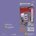
1
R8HE / PPG3HE SERIES
14 SEER / 95% AFUE
INSTALLATION INSTRUCTIONS
SINGLE PACKAGE GAS HEATING / ELECTRIC COOLING
3-PHASE & SINGLE PHASE (REVISION A)
HORIZONTAL MOUNT SHOWN
WARNING / AVERTISSEMENT
FIRE OR EXPLOSION HAZARD
•Failure to follow safety warnings exactly
could result in serious injury or property
damage.
•Installation and service must be performed
by a qualified installer, service agency or
the gas supplier.
•Do not store or use gasoline or other
flammable vapors and liquids in the vicinity
of this or any other appliance.
WHAT TO DO IF YOU SMELL GAS
•Do not try to light any appliance.
•Do not touch any electrical switch; do not
use any phone in your building.
•Leave the building immediately.
•Immediately call your gas supplier from a
neighbors phone. Follow the gas suppliers
instructions.
•If you cannot reach your gas supplier, call
the fire department.
RISQUE D’INCENDIE OU D’ EXPLOSION
• Le non-respect des avertissements de sécurité
pourrait entraîner des blessures graves, la mort
ou des dommages matériels.
• L’installation et l’entretien doivent être effectués
par un installateur qualifié, un organisme de
service ou le fournisseur de gazstaller, service
agency or the gas supplier.
• Ne pas entreposer ni utiliser de l’essence ni
d’autres vapeurs ou liquides inflammables dans le
voisinage de cet appareil, ni de tout autre appareil.
QUE FAIRE S’IL Y A UNE ODEUR DE GAZ
• Ne pas tenter d’allumer aucun appareil.
• Ne toucher à aucun interrupteur électrique;
n’utiliser aucun téléphone dans le bâtiment.
• Évacuer l’immeuble immédiatement.
• Appeler immédiatement le fournisseur de gaz en
employant le téléphone d’un voisin. Respecter à
la lettre les instructions du fournisseur de gaz.
• Si personne ne répond, appeler le service des
incendies.
DO NOT DESTROY. PLEASE READ CAREFULLY & KEEP IN A SAFE PLACE FOR FUTURE REFERENCE.
TABLE OF CONTENTS
IMPORTANT SAFETY INFORMATION............................... 3
REQUIREMENTS & CODES............................................... 4
GENERAL INFORMATION.................................................. 5
Before you install this unit............................................................ 5
Locating the Equipment............................................................... 5
Heating Load................................................................................ 5
COMBUSTION AIR & VENTING REQUIREMENTS............ 5
COMPONENT FUNCTIONS................................................ 23
EQUIPMENT MAINTENANCE............................................. 24
Heat Exchanger & Burner Maintenance...................................... 24
Cleaning of Burners...................................................................... 25
REPLACEMENT PARTS...................................................... 25
TROUBLESHOOTING......................................................... 25
Vent Termination.......................................................................... 6
Cooling Mode............................................................................... 25
Heating Mode............................................................................... 25
CIRCULATING AIR SUPPLY............................................... 7
FIGURES & TABLES........................................................... 26
Air Ducts....................................................................................... 7
Unconditioned Spaces................................................................. 7
Acoustical Duct Work................................................................... 7
UNIT INSTALLATION.......................................................... 7
Packaging Removal..................................................................... 7
Rigging & Hoisting........................................................................ 7
Clearances to Combustible Materials.......................................... 8
Ground Level................................................................................ 8
Rooftop......................................................................................... 8
Horizontal to Downflow Conversion............................................. 9
Condensate Drain (Air Conditioning)........................................... 9
Air Filter Requirements................................................................ 9
Removal of Internal Filter Rack.................................................... 9
Installing Filters in the Internal Filter Rack................................... 9
Removing Filters from Internal Filter Rack.................................. 9
ELECTRICAL WIRING......................................................... 11
Pre-Electrical Checklist................................................................ 11
Grounding..................................................................................... 11
Line Voltage.................................................................................. 11
Unbalanced 3-Phase Supply Voltage.......................................... 12
Thermostat / Low Voltage Connections....................................... 12
2-Stage Heat / 1-Stage Cool Thermostat................................. 12
Single Stage Heat / Single Stage Cool Thermostat.................. 12
Heat Anticipator............................................................................ 13
Cooling Configurations................................................................. 13
Heating Configurations................................................................. 13
Blower Speed............................................................................... 13
Configuring the Fixed Speed Blower........................................ 13
Selecting Cooling Airflow.......................................................... 13
Selecting Heating Airflow......................................................... 13
Dehumidification Options............................................................. 14
Optional Furnace Control Board Connections............................. 14
Electronic Air Cleaner............................................................... 14
Humidifier................................................................................. 14
GAS SUPPLY & PIPING...................................................... 15
Leak Check................................................................................... 15
High Altitude Conversion - Natural Gas....................................... 16
LP / Propane Gas Conversion..................................................... 16
START UP & ADJUSTMENTS............................................ 18
Pre-Start Check List..................................................................... 18
Start-Up Procedure...................................................................... 18
Air Circulation........................................................................... 18
Lighting the Appliance.............................................................. 18
Verifying System Heating......................................................... 19
Verifying & Adjusting Temperature Rise................................... 19
Gas Supply Pressure Verification & Adjustment....................... 19
Verifying the Firing Rate of the Appliance................................ 19
Measuring the Manifold Pressure............................................. 20
Adjusting the Manifold Pressure............................................... 20
Removing the Manometer/Pressure Gauge............................. 20
Verifying Over-Temperature Limit Control Operation................ 20
Verifying Burner Operation....................................................... 21
Verifying System Cooling......................................................... 21
OPERATING SEQUENCE................................................... 21
Heating Mode............................................................................... 21
Thaw Cycle Start Up / Shutdown................................................. 22
Blocked Vent / Condensate Disposal Shut Down........................ 23
Cooling Mode - Single Stage Operation...................................... 23
De-Humidification Control............................................................ 23
Fan Mode...................................................................................... 23
2
Figure 8. Unit Dimensions........................................................ 26
Table 7. Center of Gravity & Shipping Weights......................... 27
Airflow Information..................................................................... 28
Table 8. Cooling Airflow Settings.............................................. 28
Table 9. Heating Airflow Settings.............................................. 28
Table 10. Blower Performance - 2 & 2.5 Ton............................. 29
Table 11. Blower Performance - 3 Ton...................................... 30
Table 12. Blower Performance - 3.5 Ton................................... 31
Table 13. Blower Performance - 4 & 5 Ton................................ 32
Gas Information.......................................................................... 33
Table 14. Gas Pipe Capacities.................................................. 33
Table 15. Gas Flow Rates......................................................... 33
Figure 9. Gas Valve Label......................................................... 34
Electrical Data............................................................................. 35
Table 16. Electrical Data........................................................... 35
Table 17. Copper Wire Size...................................................... 35
Table 18. Thermostat Wire Gauge............................................ 35
Electrical Diagrams..................................................................... 36
Figure 10. Two Stage Heating / Single Stage Cooling
Configuration........................................................... 36
Figure 11. Fixed Speed Motor Control Board........................... 36
Figure 12. Ignition Control Board - 624817.............................. 36
Wiring Diagrams......................................................................... 37
Figure 13. Single Phase, 2-5 Ton, 208/230V........................... 37
Figure 14. Three Phase, 3-5 Ton, 208/230V............................. 38
Figure 15. Three Phase, 3-5 Ton, 460V.................................... 39
Charging Charts.......................................................................... 40
Figure 16. Charging Chart for 2 Ton Units................................ 40
Figure 17. Charging Chart for 2.5 Ton Units............................. 40
Figure 18. Charging Chart for 3 Ton Units................................ 41
Figure 19. Charging Chart for 3.5 Ton Units............................. 41
Figure 20. Charging Chart for 4 Ton Units................................ 42
Figure 21. Charging Chart for 5 Ton Units................................ 42
APPENDIX A - HEAT EXCHANGER CONDENSATE DRAIN
& VENT KIT (HORIZONTAL MOUNT APPLICATIONS)...... 43
About the Kit................................................................................. 43
Vent Pipe & Drain Hose Assembly............................................... 43
Vertical Drain Pit Method............................................................. 43
Preparing the pit....................................................................... 44
Percolation Test (Optional)....................................................... 44
Vertical Drain Pipe Installation.................................................. 44
Horizontal Drain Trench Method.................................................. 44
Preparing the Trench................................................................ 45
Horizontal Drain Pipe Installation............................................. 45
Completing the Vent Installation.................................................. 45
APPENDIX B - HEAT EXCHANGER CONDENSATE DRAIN
& VENT KIT (ROOF CURB MOUNT APPLICATIONS)....... 47
About the Kit................................................................................. 47
Before Setting unit on the Curb.................................................... 47
Setting the Unit............................................................................. 48
Completing the Heat Exchanger Condensate Drain Installation.48
Completing the Vent Pipe Installation and Assembly.................. 48
INSTALLATION / PERFORMANCE CHECK LIST.............. 52
IMPORTANT SAFETY INFORMATION
Please read all instructions before servicing this equipment.
Pay attention to all safety warnings and any other special
notes highlighted in the manual. Safety markings are
used frequently throughout this manual to designate a
degree or level of seriousness and should not be ignored.
WARNING indicates a potentially hazardous situation that
if not avoided, could result in personal injury or death.
CAUTION indicates a potentially hazardous situation that
if not avoided, may result in minor or moderate injury or
property damage.
WARNING:
ELECTRICAL SHOCK, FIRE OR
EXPLOSION HAZARD
Failure to follow safety warnings exactly could
result in serious injury or property damage.
Improper servicing could result in dangerous
operation, serious injury, death or property
damage.
• Before servicing, disconnect all electrical power
to the unit.
• When servicing controls, label all wires prior to
disconnecting. Reconnect wires correctly.
• Verify proper operation after servicing.
WARNING:
These units are fully charged with R-410A
refrigerant and ready for installation. When
a system is installed according to these
instructions, no refrigerant charging is required.
If repairs make it necessary for evacuation and
charging, it should only be attempted by qualified,
trained personnel thoroughly familiar with this
equipment. Some local codes require licensed
installation service personnel to service this
type of equipment. Under no circumstances
should the homeowner attempt to install and/or
service this equipment. Failure to comply with
this warning could result in equipment damage,
personal injury, or death.
WARNING:
Do not place combustible material on or against
the unit cabinet. Do not place combustible
materials, including gasoline and any other
flammable vapors and liquids, in the vicinity of
the unit.
WARNING:
PROPOSITION 65 WARNING: This product
contains fiberglass insulation. Disturbing the
insulation of this product during installation,
maintenance, or repair may expose you to
fiberglass insulation.
• Breathing this material may cause respiratory
irritations.
• Fiberglass insulation may also cause eye
irritation, skin sensitization, or other allergic
responses in susceptible individuals.
• Always wear goggles, disposable gloves,
long sleeved shirt, and appropriate breathing
protection when working near this insulation.
If contact with skin occurs, wash immediately
with soap and water. In case of contact with
eyes, flush immediately with water for at least
15 minutes. Contact a physician if needed.
WARNING:
The information listed below and on the next
page must be followed during the installation,
service, and operation of this unit. Unqualified
individuals should not attempt to interpret these
instructions or install this equipment. Failure
to follow safety recommendations could result
in possible damage to the equipment, serious
personal injury or death.
• Before beginning the installation, verify that the unit
model is correct for the job. The unit model number
is printed on the data label. Follow all precautions in
the literature, on tags, and on labels provided with
the equipment. Read and thoroughly understand
the instructions provided with the equipment prior to
performing the installation and operational checkout
of the equipment.
• Never test for gas leaks with an open flame. Use
a commercially available soap solution to check all
connections. See page 15.
• Installation of equipment may require brazing operations.
Installer must comply with safety codes and wear
appropriate safety equipment (safety glasses, work
gloves, fire extinguisher, etc.) when performing brazing
operations.
• This equipment is NOT to be used for temporary heating
of buildings or structures under construction.
• Use caution when handling this appliance or removing
components. Personal injury can occur from sharp metal
edges present in all sheet metal constructed equipment.
• Follow all precautions in the literature, on tags, and
on labels provided with the equipment. Read and
thoroughly understand the instructions provided with
the equipment prior to performing the installation and
operational checkout of the equipment.
• The installer should become familiar with the units wiring
3
diagram before making any electrical connections to the
unit. See the unit wiring label or Figure 13 (page 37),
Figure 14 (page 38), & Figure 15 (page 39).
REQUIREMENTS & CODES
• This equipment must be installed in accordance with
instructions outlined in this manual, all applicable
local building codes, and the current revision of
the National Fuel Gas Code (NFPA54/ANSI Z223.1)
or the Natural Gas and Propane Installation Code,
CAN/CGA B149.1.
• All electrical wiring must be completed in accordance
with local, state and national codes and regulations
and with the National Electric Code (ANSI/NFPA 70)
or in Canada the Canadian Electric Code Part 1 CSA
C.22.1.
• The installer must comply with all local codes and
regulations which govern the installation of this type
of equipment. Local codes and regulations take
precedence over any recommendations contained in
these instructions. Consult local building codes and the
National Electrical Code (ANSI CI) for special installation
requirements.
• This equipment contains liquid and gaseous refrigerant
under high pressure. Installation or servicing should only
be performed by qualified trained personnel thoroughly
familiar with this type equipment.
• Install this unit only in a location and position as specified
on page 5. This unit is designed only for outdoor
installations and should be located with consideration
of minimizing the length of the supply and return ducts.
Consideration should also be given to the accessibility
of fuel, electric power, service access, noise, shade,
and drainage for the units heat exchanger condensate
drainage pit.
• Air Ducts must be installed in accordance with the
standards of the National Fire Protection Association
“Standards for Installation of Air Conditioning and
Ventilation Systems” (NFPA 90A), “Standard for
Installation of Residence Type Warm Air Heating and Air
Conditioning Systems” (NFPA 90B), these instructions,
and all applicable local codes. See page 7 for
additional information.
• Consult Table 8 (page 28), Table 9 (page 28),
Table 10 (page 29), Table 11 (page 30), Table
12 (page 31) & Table 13 (page 32), and the rating
plate for the proper circulating air flow and temperature
rise. It is important that the duct system be designed
to provide the correct flow rates and external pressure
rise. An improperly designed duct system can result in
nuisance shutdowns, and comfort or noise issues.
4
• Use only with the type of gas approved for this unit.
Refer to the unit rating plate.
• Provide adequate combustion and ventilation air to the
unit. See page 5, page 6, & page 7.
• Provide adequate clearances around the combustion
air intake louvers. See Figure 1 (page 5).
• Combustion products must be discharged outdoors.
Connect this unit to an approved vent system only, as
specified on page 6 and in the Appendix (pages 36-38).
• The information listed below is for reference purposes
only and does not necessarily have jurisdiction over
local or state codes. Always consult with local authorities
before installing any gas appliance.
Combustion & Ventilation Air
• US: National Fuel Gas Code (NFGC), Air for Combustion
and Ventilation
• CANADA: Natural Gas and Propane Installation Codes
(NSCNGPIC), Venting Systems and Air Supply for
Appliances
Duct Systems
• US and CANADA: Air Conditioning Contractors
Association (ACCA) Manual D, Sheet Metal and
Air Conditioning Contractors National Association
(SMACNA), or American Society of Heating,
Refrigeration, and Air Conditioning Engineers (ASHRAE)
Fundamentals Handbook
Electrical Connections
• US: National Electrical Code (NEC) ANSI/NFPA 70
• CANADA: Canadian Electrical Code CSA C22.1
Gas Piping & Gas Pipe Pressure Testing
• US: NFGC and National Plumbing Codes
• CANADA: NSCNGPIC
General Installation
• US: Current edition of the NFGC and the NFPA 90B. For
copies, contact the National Fire Protection Association
Inc., Batterymarch Park, Quincy, MA 02269; or American
Gas Association, 400 N. Capitol, N.W., Washington DC
20001 or www.NFPA.org
• CANADA: NSCNGPIC. For a copy, contact Standard
Sales, CSA International, 178 Rexdale Boulevard,
Etobicoke (Toronto), Ontario, M9W 1R3 Canada
Safety
• US: (NFGC) NFPA 54–1999/ANSI Z223.1 and the
Installation Standards, Warm Air Heating and Air
Conditioning Systems ANSI/NFPA 90B.
• CANADA: CAN/CGA-B149.1 and .2–M00 National
Standard of Canada. (NSCNGPIC)
GENERAL INFORMATION
This Single Package Gas Heating / Electric Cooling
Unit is designed for outdoor rooftop or ground level
slab installations and can be readily connected to the
duct system of a home or building. This unit has been
tested for capacity and efficiency in accordance with
AHRI standards and will provide many years of safe and
dependable comfort, providing it is properly installed
and maintained. With regular maintenance, this unit will
operate satisfactorily year after year. Abuse, improper
use, and/or improper maintenance can shorten the life
of the appliance and create unsafe hazards.
To achieve optimum performance and minimize equipment
failure, it is recommended that periodic maintenance be
performed on this unit. The ability to properly perform
maintenance on this equipment requires certain tools
and mechanical skills.
Before you install this unit
√ The cooling load of the area to be conditioned must be
calculated and a system of the proper capacity selected.
It is recommended that the area to be conditioned be
completely insulated and vapor sealed.
√ Check the electrical supply and verify the power supply
is adequate for unit operation. Consideration should be
given to availability of electric power, service access,
noise, and shade. If there is any question concerning
the power supply, contact the local power company.
√ All units are securely packed at the time of shipment and
upon arrival should be carefully inspected for damage
prior to installing the equipment at the job site. Verify
coil fins are straight. If necessary, comb fins to remove
flattened or bent fins. Claims for damage (apparent or
concealed) should be filed immediately with the carrier.
√Survey the job site to determine the best location for
setting the unit. Choose an appropriate location that
minimizes the length of the supply and return air ducts.
√ Please consult your dealer for maintenance information
and availability of maintenance contracts. Please read
all instructions before installing the unit.
See Note 1
See Note 2
36"
36"
36"
Minimum Required
Clearances to Combustibles
NOTE 1: 6” When coil is present on duct side.
NOTE 2: 1” When no coil is present on duct side.
Figure 1. Clearance Requirements
Locating the Equipment
• Select a solid, level position, preferably on a concrete
slab, slightly above the grade level, and parallel to the
home. DO NOT PLACE UNIT UNDER THE HOME.
• Overhead obstructions, poorly ventilated areas, and
areas subject to accumulation of debris should be
avoided. Do not place the unit in a confined space or
recessed area where discharge air from the unit to recirculate into the condenser air inlet, through the coil.
• Sufficient clearance for unobstructed airflow through the
louvered control access panel and outdoor coil must
be maintained in order to achieve rated performance.
See Figure 1 for minimum clearances to obstructions.
• A clearance of at least 36 inches from the blower
access panel and from the louvered control access
panel is recommended for servicing and maintenance.
Where accessibility clearances are greater than
minimum clearances to combustibles, accessibility
clearances must take preference.
• The hot condenser air must be discharged up and away
from the home, and if possible, in a direction with the
prevailing wind.
• If practical, place the air conditioner and its ducts in an
area where they will be shaded from the afternoon sun,
when the heat load is greatest.
Heating Load
This unit should be sized to provide the design heating
load requirement. Heating load estimates can be made
using approved methods available from Air Conditioning
Contractors of America (Manual J); American Society of
Heating, Refrigerating, and Air Conditioning Engineers;
or other approved engineering methods. For installations
above 2,000 ft., the unit should have a sea level input
rating large enough that it will meet the heating load after
deration for altitude.
COMBUSTION AIR & VENTING
REQUIREMENTS
WARNING:
Installation methods other than those described
in the following sections must comply with the
National Fuel Gas Code and all applicable local
codes for providing sufficient combustion air
to the unit.
• Provisions must be made during the installation of
this unit that provide an adequate supply of air for
combustion.
• Instructions for determining the adequacy of an
installation can be found in the current revision of the
NFGC (ANSI Z223.1 / NFPA54). Consult local codes
for special requirements. These requirements are for
US installations as found in the NFGC.
• The requirements in Canada (B149.1) are structured
differently. Consult with B149.1 and local code officials
for Canadian installations.
5
WARNING:
Combustible air must not be drawn from a
contaminated atmosphere. Excessive exposure
to contaminated combustion air will result in
safety and performance related problems.
To maximize heat exchanger life, the combustion air
must be free of chemicals which form corrosive acidic
compounds in the combustion gases.
IMPORTANT NOTE:
Do not store any chemicals with flammable or caustic
vapors near the vent termination. Some examples of
these chemicals are:
• Carbon tetrachloride
• Gasoline/Kerosene
• The vent termination must be located at least 3 feet
above any forced air inlet located within 10 feet.
• The vent termination must be located at least 4 feet
below, 4 feet horizontally from, or 1 foot above any
door, window, or gravity air inlet into any building.
• The unit should be installed in a way that prevents any
obstruction of the vent termination during accumulating
snow.
• Verify exhaust gases will not impinge on windows
or building surfaces, which may be compromised or
damaged by condensation.
• Do not install the unit such that exhaust from the vent
termination is directed into window wells, stairwells,
under decks, or in alcoves or similarly recessed areas.
HORIZONTAL GROUND MOUNT
• Cements, glues, paint removers,
• Halogen type refrigerants
varnishes, etc.
• Cleaning solvents
• Chlorine
• Hydrochloric acid
based swimming pool
chemicals
• Masonry acid washing materials
• Chlorinated waxes & cleaners • Permanent wave solutions
• De-icing salts or chemicals
• Water softening chemicals
Vent Termination
This unit has been developed for use with a combination
heat exchanger condensate drain and venting system
designed to operate only with this type of system.
Condensate Drain and Vent Kits are available for purchase
as accessory items.
Horizontal ground mount applications can use P/N-922323
to attach the 13.25” x 2” PVC pipe within the control area of
this unit. Rooftop mount applications can use the downflow
condensate drain / vent kit (P/N-922485).
Combined condensate
Drain / Vent System
ROOF MOUNTED UNIT
(ROOF CURB AND ROOF NOT SHOWN)
If Nordyne kits are not being used, see Appendix on page
43 or page 45 for your specific application.
WARNING:
This unit is intended for outdoor installation
only. This unit must be vented to the outdoors.
No additional venting shall be used. Do not vent
the unit through a conventional venting system.
The vent and drain assembly must be installed to
assure proper operation of the unit. Figure 2 shows the
proper installation of the vent and drain assembly for both
horizontal and downflow applications. The fasteners used
to secure the vent and drain assembly have been included
in the kit. The following list summarizes the requirements
for the location of the vent system termination:
• The location of the vent termination must be consistent
with the National Fuel Gas Code (ANSI Z223.1) or CAN/
CGA-B149 Installation Codes.
• The vent termination must be located at least 4 feet
horizontally from any electric meters, gas meters,
regulators, and relief equipment.
6
2” PVC x 22.5 Degree Elbow
& 1/4” Mesh Screen
Figure 2. Heat Exchanger Condensate Drain
& Vent Assembly
CIRCULATING AIR SUPPLY
WARNING:
Products of combustion must not be allowed to
enter the return air ductwork or the circulating air
supply. Failure to prevent products of combustion
from being circulated into the living space can
create potentially hazardous conditions including
carbon monoxide poisoning that could result in
personal injury or death.
All return ductwork must be adequately sealed,
all joints must be taped, and the ductwork must
be secured to the unit with sheet metal screws.
When return air is provided through the bottom
of the unit, the joint between the unit and the
return air plenum must be air tight.
The roof curb or cement pad that the unit is
mounted must provide sound physical support of
the unit with no gaps, cracks, or sagging bewteen
the unit and pad.
Return air and circulating air ductwork must not
be connected to any other heat producing device
such as a fireplace insert, stove, etc. Doing so
may result in fire, explosion, carbon monoxide
poisoning, personal injury, or property damage.
Air Ducts
This unit is designed only for use with a supply and return
duct. Air ducts should be installed in accordance with the
standards of the National Fire Protection Association
“Standard for Installation of Air Conditioning Systems”
(NFPA 90A), “Standard for Installation of Residence Type
Warm Air Heating and Air Conditioning Systems” (NFPA
90B), and all applicable local codes. NFPA publications
are available by writing to: National Fire Protection
Association, Batterymarch Park, Quincy, ME 02269 or
visit www.NFPA.org on the web.
• Design the duct work according to Manual D by the Air
Conditioning Contractors of America (ACCA).
• The ducts must be properly sized not to exceed the
units maximum ESP rating at 400 SCFM per nominal
ton of cooling capacity.
• Duct work should be attached directly to the unit flanges
for horizontal applications.
• If a roof curb is installed, the ducts must be attached to
the curb hangers, not the unit.
• It is recommended that the outlet duct be provided
with a removable access panel. The opening should
be accessible when the unit is installed in service and
shall be sizes so that smoke or reflected light may be
observed inside the casing to indicate the presence of
leaks in the heat exchanger. The cover for the opening
shall be attached in a way that will prevent leaks.
• If outside air is utilized as return air to the unit for
ventilation or to improve indoor air quality, the system
must be designed so that the return air to the unit is not
less than 50° F (10° C) during heating operation.
• If a combination of indoor and outdoor air is used, the
ducts and damper system must be designed so that the
return air supply to the furnace is equal to the return air
supply under normal, indoor return air applications.
Unconditioned Spaces
All duct work passing through unconditioned space must
be properly insulated to minimize duct losses and prevent
condensation. Use insulation with an outer vapor barrier.
Refer to local codes for insulation material requirements.
Acoustical Duct Work
Certain installations may require the use of acoustical
lining inside the supply duct work.
• Acoustical insulation must be in accordance with the
current revision of the Sheet Metal and Air Conditioning
Contractors National Association (SMACNA) application
standard for duct liners.
• Duct lining must be UL classified batts or blankets with
a fire hazard classification of FHC-25/50 or less.
• Fiber duct work may be used in place of internal duct
liners if the fiber duct work is in accordance with the
current revision of the SMACNA construction standard
on fibrous glass ducts. Fibrous duct work and internal
acoustical lining must be NFPA Class 1 air ducts when
tested per UL Standard 181 for Class 1 ducts.
UNIT INSTALLATION
Packaging Removal
Remove the shipping carton and User’s Manual from the
equipment. Set aside the 13” x 2” PVC pipe for later use
when installing the heat exchanger condensate drain and
vent kit. Take care not to damage the coil or cabinet when
removing the carton. For rooftop installations, remove
and discard the two supports attached beneath the unit
Rigging & Hoisting
WARNING:
To avoid the risk of property damage, personal
injury, or death, it is the rigger’s responsibility
to ensure that whatever means are used to hoist
the unit are safe and adequate:
• The lifting equipment must be adequate for the
load. Refer to Table 7 (page 27) for unit weights.
• The unit must be lifted from the holes in the
base rails using cables or chains.
• Spreader bars are required to protect the unit
and ensure even loading.
• Keep the unit in an upright position at all times.
The rigging must be located outside the units
center of gravity. Refer to Figure 7 (page 20)
for locating the center of gravity.
• All panels must be securely in place during
rigging and hoisting, except control access
panel. See page 48 for additional lifting and
setting of unit requirements.
7
Clearances to Combustible Materials
These units are certified as combination heating and
cooling equipment for outdoor rooftop or ground level
installations. Units may be installed on combustible
flooring or class A, B, or C roofing material when used
with bottom supply and return air ducts as long as the
following requirements are met:
• If using bottom discharge with return air ducts a roof
curb must be installed prior to unit installation. See
Rigging and Hoisting section for setting of the unit.
• Sufficient clearance for unobstructed airflow through the
outdoor coil must also be maintained in order to achieve
rated performance. For information about locating the
equipment, see page 5.
GROUND LEVEL INSTALLATION
Ground Level
Ground level installations must be located according to
local building codes or ordinances and these requirements:
• Clearances must be in accordance with those shown
in Figure 1 (page 5).
• A suitable mounting pad must be provided and be
separate from the building foundation. The pad must be
level to ensure proper condensate disposal and strong
enough to support the unit’s weight. The slab height
must be a minimum of 2” (5cm) above grade and with
adequate drainage. See Figure 3.
• Remove and discard the horizontal Supply and Return
duct covers located on the rear of the unit. Form duct
attachment flanges by bending the sheet metal outward
90 degrees along the perforated lines.
• Firmly attach ductwork directly to these flanges with
screws or other approved mechanical connections and
not to the Supply/Return air panels to avoid damage to
internal components of the equipment. Use approved
duct sealing methods to ensure an air and watertight
seal is achieved.
Rooftop
Rooftop installations must be located according to local
building codes or ordinances and these requirements:
• The roof must be capable of handling the weight of the
unit. Reinforce the roof if necessary For unit weights,
see Table 7 (page 27).
• The appropriate accessory roof curb must be installed
prior to unit installation. The roof curb must be square
and level to ensure proper condensate drainage. See
Figure 2 (page 6). Please follow all instructions
provided with the kit.
• Secure roof curb or frame to roof using acceptable
mechanical methods per local codes. NOTE: Make sure
the two supports beneath the unit have been removed.
2”
ROOFTOP INSTALLATION
ACCESSORY
ROOF CURB
Figure 3. Ground & Rooftop Installation
8
IMPORTANT NOTES TO INSTALLER
• When setting the roof curb for installation, routing and
securement of the gas heat exchanger condensate
drain line must be determined and installed prior to
setting the unit on the curb. It is recommended to drill
a 1.00”-1.25” diameter hole through the roof below
the rectangular opening located in outer close off curb
panel (G) of Nordyne offered curbs, approximately 15”
in from the short side of curb and 1”-2” in from the long
side of curb. If drilling a hole is not an option, routing the
condensate drain hose over to the duct passage opening
with enough slope is acceptable as long as drain line is
secured to curb and duct, ensuring no kinks or traps can
form between the collector box drain or interior of the
building. Leave a minimum of 24” drain line extending
out the top of roof curb front close off panel (G) for
passage through unit bottom and connection to unit
drain when unit is being set. See unit or Condensate/
Vent Drain Kit (P/N-922485) instructions for completion
of the drain connection.
• It is recommended no non-serviceable connections are
introduced in the drain line between unit drain connection
and an accessible area within the building interior.
• Securement of the drain line to the inside surface of
the roof curb is acceptable and should be made in the
wood nailer area (top 3.5”) to avoid possible leaks or
penetrations to roofing materials.
• Cut and remove the insulation covering the 2” x 3”
condensate drain passage in outer panel (G) only. Before
installing inner panel (G) ensure there is enough slope
and there are no kinks or high spots that could trap
water in the line prior to entering the warmer interior of
the building where a drain trap is acceptable.
• All panels must be securely in place during rigging and
hoisting, except control access panel. See page 48
for additional lifting and setting of unit requirements.
Horizontal to Downflow Conversion
The unit is shipped ready for horizontal duct connections.
If down flow ducts are required, the unit must be converted
following the steps below for both the supply and return
ducts.
1.Remove both horizontal duct caps.
2.Locate the duct cap inside the duct openings and remove
the screw holding it in place.
3.Lift the cap out of the unit. (Hint: The cap can be pushed
up from the bottom by reaching through the fork slot).
4.Cover the horizontal duct openings with the horizontal
duct caps removed earlier in step 1. The insulation will
be on the indoor side.
5.Fasten the cover with screws to seal.
6.Remove and discard the two wood supports beneath
the unit.
Condensate Drain (Air Conditioning)
Air conditioning condensate is removed from the unit
through the 3/4” female pipe and supplied fitting located
on the front side of the unit. Figure 4 (page 10).
Install a 2 inch condensate trap in the drain line of the
same size and prime with water. When connecting rigid
drain line, hold the female fitting with a wrench to prevent
twisting. Do not over tighten! Refer to local codes and
restrictions for proper condensate disposal requirements.
Air Filter Requirements
WARNING:
Never operate the unit without a filter in place.
Dust and lint could accumulate on internal parts,
resulting in loss of efficiency, equipment damage
and possible fire.
NOTE TO INSTALLER: After installing or replacing the
filtration system for this unit, add the following statement
on or adjacent to the filter service panel: “Replace
filter(s) installed in your system only with the same
dimensional size filters that are being replaced.”
• A suitable air filter must be installed upstream of the
evaporator coil of the return air system. For recommended
external filter sizes, refer to Table 1 (page 10).
• All return air must pass through the filters before entering
the evaporator coil. It is important that all filters be kept
clean and replaced frequently to ensure proper operation
of unit. Dirty or clogged filters will reduce the efficiency
of the unit and result in unit shutdowns.
• Air filter pressure drop is recommended not to exceed
0.08 inches WC.
• Single phase downflow applications require either a
Nordyne internal filter kit be used or an air filter system
be installed in the return air ductwork. Three phase
models are factory equipped with an internal filter rack
ready to accept field supplied filters. See Table 1 for
specific unit model and filter sizes. Nordyne internal
filter rack adjusts for 1” or 2” filters.
• Horizontal installations require the air filter system be
installed in the return air ductwork.
Removal of Internal Filter Rack
(If Equipped, only required if economizer is
installed)
1.Remove the return air panel from the unit.
2.Remove the height adjustment screw from the inside
of the rack.
3.Remove (1) screw securing the assembly to the coil
located on the left leg of the rack. NOTE: The assembly
can now be easily collapsed and removed from the unit.
See Figure 5 (page 10) for filter rack securing screw
locations.
Installing Filters in the Internal Filter Rack
(If Equipped)
1.Remove access panel screws from return air panel.
(Hint: Loosen the unit’s top panel screws near the
top edge of the access panel. The access panel was
designed to be captured underneath the top panel.)
2.Slide the first filter between both guide channels of filter
rack and allow the filter to drop easily into place.
3.Verify the bottom of the filter is within the channels of
the rack.
4.Slide the 2nd filter (and 3rd filter on taller models)
between both guide channels of filter rack.
5.Verify the top of the filter is within the channels of the
rack.
6.Replace access cover by sliding the top edge of panel
under the lip of the unit’s top panel. Secure access
panel by replacing the screws.
Removing Filters from Internal Filter Rack
(If Equipped)
1.Remove access panel screws from return air panel.
(Hint: Loosen the unit’s top panel screws near the
top edge of the access panel. The access panel was
designed to be captured underneath the top panel.)
2.Remove upper filter by gently pulling filter through the
access panel opening.
3.Remove lower filter by lifting media to top of filter rack.
Remove in the same manner as described in step 2.
4.Install new filter in the filter rack as described in the
previous section.
9
EXTERNAL FILTER SIZES
NOMINAL
COOLING
(TONNAGE)
FILTER SIZE
(IN. X IN.)
APPROXIMATE
AIR FLOW
RANGE (CFM)
APPROXIMATE
FILTER AREA
(SQ. IN.)*
2.0
2.5
20 x 25
600-900
450
20 x 30
750-1200
550
3.0
25 x 25
1100-1300
625
3.5
24 x 30
1200-1600
750
4.0
18 x 24 (2 required)
1400-1800
850
5.0
20 x 25 (2 required)
1700-2200
1000
APPROXIMATE
AIR FLOW
RANGE (CFM)
APPROXIMATE
FILTER AREA
(SQ. IN.)*
INTERNAL FILTER SIZES
CABINET
HEIGHT
30”
34”
38”
42”
OUTDOOR
FAN
DIAMETER
FILTER SIZE
(IN. X IN.)
20
(2) 14”x25”
24”
(1) 12”x20” and (1) 16”x25”
20
(2) 16”x25”
24”
(1) 12”x20” and (2) 10”x25”
20”
(2) 18”x25”
24”
(1) 12”x20” and (2) 12”x25”
20”
(2) 20”x25”
24”
(1) 12”x20” and (2) 14”x25”
700 - 1300
900 - 1400
1100 - 1600
1300 - 1800
700
640
800
740
900
840
1000
940
* Based on velocity of 300 ft/min for disposable filters.
Table 1. External & Internal Filter Sizes
HIGH SIDE
Securing
Screws
LOW SIDE
CONDENSATE
DRAIN
Figure 4. Refrigerant Service Ports & Air
Conditioning Condensate Drain Locations
10
Figure 5. Internal Filter Rack Location
ELECTRICAL WIRING
WARNING:
ELECTRICAL SHOCK, FIRE OR
EXPLOSION HAZARD
Failure to follow safety warnings exactly could
result in serious injury or property damage.
Improper servicing could result in dangerous
operation, serious injury, death or property
damage.
• Before servicing, disconnect all electrical
power to furnace.
• When servicing controls, label all wires prior
to disconnecting. Reconnect wires correctly.
• Verify proper operation after servicing.”
AVERTISSEMENT:
RISQUE DE CHOC ÉLECTRIQUE,
D’INCENDIE OU D’EXPLOSION
Le non-respect des avertissements de
sécurité pourrait entraîner un fonctionnement
dangereux de l’appareil, des blessures graves,
la mort ou des dommages matériels.
Un entretein incorrect pourrait entraîner un
fonctionnement dangereux de l’appareil, des
blessures graves, la mort ou des dommages
matériels
• Couper toute alimentation électrique au
générateur d’air chaud avant de prodéder
aux travaux d’entretein.
• Au moment de l’entretien des commandes,
étiquetez tous les fils avant de les débrancher.
S’assurer de les raccorder correctement.
• S’assurer que l’appareil fonctionne
adéquatement aprés l’entretien.
• Electrical connections must be in compliance with all
applicable local codes with the current revision of the
National Electric Code (ANSI/NFPA 70).
• For Canadian installations the electrical connections
and grounding shall comply with the current Canadian
Electrical Code (CSA C22.1 and/or local codes).
IMPORTANT NOTE:
If replacing any of the original wires supplied with the
furnace, the replacement wire must be copper wiring
having the same guage, voltage, and temperature
rating.
Pre-Electrical Checklist
(Single & 3-Phase Models)
√Verify the voltage, frequency, and phase of the supply
source match the specifications on the unit rating plate.
√ Verify that the service provided by the utility is sufficient
to handle the additional load imposed by this equipment.
See Table 16 (page 35) (or the unit rating label) for
proper high voltage wiring requirements.
√ Verify factory wiring is in accordance with the unit wiring
diagram. Figure 13 (page 37), Figure 14 (page 38),
& Figure 15 (page 39). Make sure the connections
didn’t loosen during shipping or installation.
√Phase balance on 3 phase units must always be
checked. See Unbalanced 3-Phase Supply Voltage
section (page 12).
Grounding
WARNING:
The unit cabinet must have an uninterrupted or
unbroken electrical ground to minimize personal
injury if an electrical fault should occur. Do not
use gas piping as an electrical ground!
This unit must be electrically grounded in accordance with
local codes or, in the absence of local codes, with the
National Electrical Code (ANSI/NFPA 70) or the CSA C22.1
Electrical Code. Grounding of the unit is accomplished
by using the grounding lug provided in the control box.
Line Voltage
• The line voltage to the unit should be supplied from a
dedicated branch circuit containing the correct fuse or
circuit breaker for the unit.
• An electrical disconnect must be located within sight
of and readily accessible to the unit. This switch shall
be capable of electrically de-energizing the outdoor unit.
See unit data label for proper incoming field wiring. Any
other wiring methods must be acceptable to authority
having jurisdiction.
• Use only copper wire for the line voltage power supply
to this unit. See Table 17 (page 35). Use proper
code agency listed conduit and a conduit connector
for connecting the supply wires to the unit. Use of rain
tight conduit is recommended.
• Provide power supply for the unit in accordance with
the unit wiring diagram and the unit rating plate.
• Overcurrent protection must be provided at the branch
circuit distribution panel and sized as shown on the unit
rating label and according to applicable local codes.
See Table 16 (page 35) or the unit rating plate for
minimum circuit ampacity and maximum overcurrent
protection limits.
• A wiring diagram is located on the inside cover of the
control access panel of the outdoor unit. The installer
should become familiar with the wiring diagram before
making any electrical connections to the outdoor unit.
See Figure 13 (page 37), Figure 14 (page 38), &
Figure 15 (page 39).
11
• All 208-240 volt units are shipped from the factory wired
for 240 volt transformer operation. For 208V operation,
remove the lead from the transformer terminal marked
240V and connect it to the terminal marked 208V.
• Connect the line-voltage leads to the terminals on the
contactor inside the control compartment.
Unbalanced 3-Phase Supply Voltage
Voltage unbalance occurs when the voltages of all phases
of a 3-phase power supply are no longer equal. This
unbalance reduces motor efficiency and performance.
Some underlying causes of voltage unbalance may
include: Lack of symmetry in transmission lines, large
single-phase loads, and unbalanced or overloaded
transformers. A motor should never be operated when a
phase imbalance in supply is greater than 2%.
Perform the following steps to determine the percentage
of voltage imbalance:
1.Measure the line voltages
of your 3-phase power
supply where it enters
the building and at a
location that will only
be dedicated to the
unit installation. (at the
units circuit protection or
disconnect).
EXAMPLE:
AB = 451V
BC = 460V
AC = 453V
2.Determine the average voltage in the power supply.
In this example, the measured line voltages were 451,
460, and 453. The average would be 454 volts (451 +
460 + 453 = 1,364 / 3 = 454).
3.Determine the maximum deviation:
EXAMPLE
From the values given in step 1, the BC voltage (460V)
is the greatest difference in value from the average:
Highest Value
460 - 454 = 6
454 - 451 = 3
454 - 453 = 1
4.Determine percent of
voltage imbalance by
using the results from
steps 2 & 3 in the following
equation.
% Voltage Imbalance = 100 x
EXAMPLE
100 x
6
= 1.32%
454
max voltage deviation
from average voltage
average voltage
The amount of phase imbalance (1.32%) is satisfactory
since the amount is lower than the maximum allowable
2%. Please contact your local electric utility company if
your voltage imbalance is more than 2%.
12
Thermostat / Low Voltage Connections
• This unit is designed to operate from a 24 VAC Class II
control circuit. A single stage cooling / two stage heating
thermostat should be used with this unit. See Figure 10
(page 36) for typical thermostat connection.
• The control circuit wiring must comply with the current
provisions of the NEC (ANSI/NFPA 70) and with
applicable local codes having jurisdiction. Thermostat
connections should be made in accordance with the
instructions supplied with the thermostat and the indoor
equipment.
• The low voltage wires must be properly connected.
Route 24V control wires through the sealing grommet
near the power entrance. Recommended wire gauge
and wire lengths for typical thermostat connections are
listed in Table 18 (page 35).
• Several thermostat options are available depending
on the accessories installed with the unit. Select a
thermostat that operates in conjunction with the installed
accessories.
• The thermostat should be mounted about 5 feet above
the floor on an inside wall. DO NOT install the thermostat
on an outside wall or any other location where its
operation may be adversely affected by radiant heat from
fireplaces, sunlight, or lighting fixtures, and convective
heat from warm air registers or electrical appliances.
Refer to the thermostat manufacturer’s instruction sheet
for detailed mounting information.
2-Stage Heat / 1-Stage Cool Thermostat
(Recommended): For highest efficiency a 2 Stage Heating/
Single Cooling thermostat is recommended for this unit. A
Single Stage Cool thermostat is only required for cooling
operation control of this unit. A 2 Stage Heat thermostat
will allow the gas heat to operate at a more efficient low
heat condition until there is a demand for higher heat
output to the conditioned space.
Single Stage Heat / Single Stage Cool
Thermostat
(Optional): A Single Stage Cool thermostat is only required
for cooling operation of this unit. A Single Stage Heat
thermostat can be used in conjunction with the automatic
heat staging jumper on the ignition control board. The heat
staging function will automatically move the unit into high
heat operation after 10 minutes when the jumper is moved
from OFF to the ON position. See Figure 12 (page 36).
Connect the Red, Yellow, Green, White, and Brown low
voltage thermostat wires to terminals R, Y1 (1st Stage
Cool), G, W1 (1st Stage Heat), & W2 2nd Stage Heatoptional) on both the thermostat sub-base and unit low
voltage terminal board. The C terminal (Black wire), is the
24V common wire required on some thermostat models.
See Figure 10 (page 36).
Heat Anticipator
Verify if the thermostat being used for the installation
has a heat anticipator setting. This function allows the
thermostat to anticipate the space heating rate and time
the burner to shutoff accordingly. Always refer to the
thermostat manufacturer’s instructions for correct settings.
• Add the current draw of the system heating components.
OR
• Measure the current flow on the thermostat R-W circuit
after the circulating blower motor has started. Set the heat
anticipator according to the thermostat manufacturer’s
instructions for heat anticipator settings.
Cooling Configurations
This unit is designed to connect with any single stage
cooling thermostat. The connection between Y1 on the
thermostat and Y1 on the unit terminal strip energizes
cooling operation. See Figure 10 (page 36).
Heating Configurations
This gas pack is factory configured for two stage gas
heating operation with a two stage heating thermostat.
Connect the low voltage thermostat White & Brown wires
to W1 & W2, between the unit low voltage terminal board
and thermostat sub-base. See Figure 10.
To operate with a single stage heat thermostat, only
connect the low voltage thermostat White wire between
W1 on the unit low voltage terminal board and thermostat
sub-base. Reposition the automatic heat staging jumper
located on the ignition control module from OFF to ON
to set a 10 minute time delay before the gas furnace will
automatically move to high heat operation. NOTE: When
low fire on the gas valve is energized, the furnace operates
in low fire mode at a lower blower speed and the timer
begins its delay function. If the room thermostat is not
satisfied before the timer activates, the furnace will stage
to high fire. The inducer motor and blower will ramp to a
higher speed until the thermostat is satisfied.
Blower Speed
The blower speed is preset at the factory for proper
fan only, heating, and cooling operation. These factory
settings are listed in Table 8 (page 28), Table 9 (page
28), Table 10 (page 29), Table 11 (page 30), Table
12 (page 31) & Table 13 (page 32). For optimum
system performance and comfort, it may be necessary to
change the factory set speed. To avoid personal injury
or property damage, make sure the motor leads do
not come into contact with any un-insulated metal
components of the unit.
NOTES:
• The CFM values listed in Table 8, Table 9, Table 10,
Table 11, Table 12 & Table 13 are DEPENDANT on
duct static pressure for individual switch settings.
• If coil icing occurs, the basic cooling airflow selected
may be too low. Verify the selected setting is within
the range shown in Table 8 and the system is properly
charged. If icing continues, raise the selected airflow
to the next higher tap.
• For maximum dehumidification and energy efficiency,
select an airflow near the middle or bottom of the CFM
range for that nominal capacity.
• The 2-stage heating feature of the unit requires
modulating the airflow. The unit will automatically adjust
the airflow to the appropriate rate when the unit heating
capacity changes.
Configuring the Fixed Speed Blower
The fixed speed blower assembly has been designed to
give the installer maximum flexibility for optimizing system
performance, efficiency, and comfort. It is equipped with
a microprocessor-controlled motor when coupled with a
fixed speed motor control board delivers constant torque
to optimize airflow in a variety of conditions and system
configurations. Because the blower can be configured in
many ways, it is important to read and follow all instructions
carefully.
Upon initial start up, the fixed speed blower must be
checked so that the factory settings match the unit with
the system, climatic conditions, and other system options.
With the blower installed and configured properly, the
furnace will change speed in response to changes in
system variables such as Heat/Cool setting, Fan Auto/
On, or 2 Stage furnace High/Low Heat. The fixed speed
blower is configured by setting the 8 switches for heating
and cooling operation located on the blower control board.
Use pins 1 to 4 to set the blower speed for heating and
pins 5 to 8 to set the speed for cooling. To determine the
appropriate switch settings for your installation, see Table
9, Table 10, Table 11, Table 12 & Table 13 for heating or
Table 8 for cooling. See Figure 10 (page 36) for switch
locations. NOTE: For change in blower speed selection to
take effect, system power must be cycled off then restored
after 10 seconds.
Selecting Cooling Airflow
(Switches # 5, 6, 7, & 8)
The COOLING airflow is selected by setting switches # 5,
6, 7, & 8 on the motor control board (Figure 10). Table 8
(page 28) lists the recommended airflow values (CFM)
and switch settings for each nominal cooling system
capacity. All airflows for other modes of operation are
determined by these basic settings. For maximum capacity,
generally, a selection near the middle or top of the CFM
range for that nominal capacity is used. Factory settings
are displayed in BOLD ITALICS
Selecting Heating Airflow
(Switches # 1, 2, 3, & 4)
The HEATING airflow is selected by setting switches #
1, 2, 3, & 4 on the motor control board (Figure 10, Page
31). Table 9, Table 10, Table 11, Table 12 & Table 13
list the recommended airflow values (CFM) and switch
settings for each heat exchanger capacity. All airflows are
determined by these basic settings. For most applications
the factory heat setting will operate at a nominal rise based
on the furnace’s nominal efficiency and firing input. Follow
across the table row to find the switch setting and nominal
13
air-flow. Verify the selected rise is within the specification
shown on the furnace rating label or in the tables.
Dehumidification Options
The fixed speed motor control board has a DEHUM
connection that allows the system to increase the amount
of humidity that is removed from the circulating air. This
is accomplished by reducing the CFM and allowing the
cooling coil to become colder. This function is only available
when there is a call for cooling. There are many ways this
function can be electrically wired.
CAUTION:
To avoid personal injury or property damage,
make sure the motor leads do not come into
contact with any uninsulated metal components
of the unit.
Optional Furnace Control Board
Connections
Electronic Air Cleaner
When 24VAC is present at the DEHUM terminal of the
The furnace control board provides output terminals
blower control board the airflow requirements will be
reduced to approximately 75% of the nominal airflow
requirements. If the humidity level of the conditioned space
decreases during the cycle and the humidistat opens, the
airflow will be restored to 100% of the selected value.
• If the room thermostat incorporates a humidity sensor
and DEHUM output, connect the DEHUM on the
thermostat to the DEHUM terminal on the motor control
board. See Figure 10 (page 36).
• If using a separate humidistat, connect the DEHUM & R
terminals on the humidistat to the DEHUM & R terminals
on the motor control board. In this option, the DEHUM
output of the humidistat must be set to be normally open
and closed when there is a call for dehumidification.
If a humidistat is not available, it is an acceptable option
to directly jumper the R & DEHUM on the blower control
board. NOTE: This option will always operate the blower
at 75% the rated airflow for the first 10 minutes of every
cooling cycle no matter what the humidity level of the
home is. See Figure 10.
14
for an optional electronic air cleaner (EAC) that can be
installed in the return air duct of your system. The EAC
output is energized any time the HEAT or COOL blower
speed is energized. Control ratings are 1.0 Amp. @ 240
VAC. Output connections are made via board terminals
labeled EAC and NEUTRAL.
Humidifier
The furnace control board provides output terminals for
an optional humidifier (HUM) that can be installed on
your system. The HUM output is energized any time the
furnace inducer motor is energized. Control ratings are
1.0 Amp. @ 240 VAC. Output connections are made via
board terminals labeled HUM and NEUTRAL.
Check all factory wiring to the proper unit wiring diagram:
Figure 13 (page 37), Figure 14 (page 38), & Figure 15
(page 39). Inspect the factory wiring connections and
make sure they didn’t loosen during shipping or installation.
GAS SUPPLY & PIPING
WARNING:
FIRE OR EXPLOSION HAZARD
• Failure to follow safety warnings exactly could
result in serious injury or property damage.
• Installation and service must be performed
by a qualified installer, service agency or the
gas supplier.
• Do not store or use gasoline or other flammable
vapors and liquids in the vicinity of this or any
other appliance.
WHAT TO DO IF YOU SMELL GAS
• Do not try to light any appliance.
• Do not touch any electrical switch; do not use
any phone in your building.
• Leave the building immediately.
• Immediately call your gas supplier from a
neighbor’s phone. Follow the gas supplier’s
instructions.
• If you cannot reach your gas supplier, call the
fire department.
AVERTISSEMENT:
RISQUE D’INCENDIE OU D’ EXPLOSION
• Le non-respect des avertissements de sécurité
pourrait entraîner des blessures graves, la
mort ou des dommages matériels.
• L’installation et l’entretien doivent être
effectués par un installateur qualifié, un
organisme de service ou le fournisseur de
gazstaller, service agency or the gas supplier.
• Ne pas entreposer ni utiliser de l’essence ni
d’autres vapeurs ou liquides inflammables
dans le voisinage de cet appareil, ni de tout
autre appareil.
QUE FAIRE S’IL Y A UNE ODEUR DE GAZ
• Ne pas tenter d’allumer aucun appareil.
• Ne toucher à aucun interrupteur électrique;
n’utiliser aucun téléphone dans le bâtiment.
• Évacuer l’immeuble immédiatement.
• Appeler immédiatement le fournisseur de
gaz en employant le téléphone d’un voisin.
Respecter à la lettre les instructions du
fournisseur de gaz.
• Si personne ne répond, appeler le service des
incendies.
• All gas piping must be installed in compliance with
local codes and utility regulations. In the absence
of local codes the gas line installation must comply
with the latest edition of the National Fuel Gas Code
ANSI Z223.1 or CAN/CGA B149 Installation Codes.
• Some local codes require the installation of a
manual main shut-off valve and ground joint union
external to the unit. The shut-off valve should be
readily accessible for service and/or emergency
use. Consult the local utility or gas supplier for
additional requirements regarding placement of
the manual main gas shut-off. See Figure 6 (page
16).
• The manifold pressure must be set to the appropriate
value for your installation. To measure and adjust
the manifold pressure see page 20.
• Gas piping must never run in or through air ducts,
chimneys, gas vents, or elevator shafts.
• Compounds used to seal joints on gas piping must
be resistant to the actions of LP propane gas.
• The main gas shutoff valve and main power
disconnect to the unit must be properly labeled
by the installer in case emergency shutdown is
required.
• An 1/8 inch NPT plugged tap can be installed in the
gas line immediately upstream of the gas supply
connection to the unit for use when measuring
the gas supply pressure when not using the inlet
pressure tap supplied on the factory installed gas
valve. The plug should be readily accessible for
service use.
• A drip leg should be installed in the vertical pipe
run to the unit. See Figure 6.
This unit only has right side gas entry. When connecting
the gas, provide clearance between the gas supply line
and the entry hole in the unit’s casing to avoid unwanted
noise and/or damage to the unit. A typical gas service
hookup is shown in Figure 6.
Table 14 (page 33) lists gas pipe capacities for standard
pipe sizes as a function of length in typical applications
based on nominal pressure drop in the line.
Leak Check
WARNING:
FIRE OR EXPLOSION HAZARD
Never test for gas leaks with an open flame. Check
all connections using a commercially available
soap solution. A fire or explosion may result
causing property damage, personal injury or
loss of life. Failure to follow the safety warnings
exactly could result in serious injury, death or
property damage.
After the gas piping to the unit is complete, all connections
must be tested for gas leaks. This includes pipe connections
at the main gas valve, emergency shutoff valve and
other gas connectors. A soap and water solution can be
15
applied on each joint or union using a small paintbrush.
If any bubbling is observed, the connection is not sealed
adequately and must be retightened. Repeat the tightening
and soap check process until bubbling ceases.
LP / Propane Gas Conversion
• If pressure testing the gas supply lines at pressures
greater than 1/2 psig (14 inches WC), the unit must
be disconnected from the gas supply piping system
to prevent damage to the gas valve.
• If the test pressure is less than or equal to 1/2 psig
(14 inches WC), the unit must be isolated from the
gas supply line by closing the manual shut-off valve.
This unit was equipped at the factory for use
with natural gas only. A special kit, supplied by
the manufacturer, is required to convert the unit
to operate on LP/propane gas. Failure to use the
proper conversion kit can cause fire, explosion,
property damage, carbon monoxide poisoning,
personal injury, or death.
High Altitude Conversion - Natural Gas
Conversion of this unit must be performed by qualified
service personnel, using only approved parts. All
installations must be made in accordance with the National
Fuel Gas Code and/or local jurisdiction codes.
WARNING:
The reduction of input rating necessary for high
altitude installation may only be accomplished
with factory supplied orifices. Do not attempt to
drill out orifices in the field. Improperly drilled
orifices may cause fire, explosion, carbon
monoxide poisoning, personal injury or death.
High altitude conversion can be field performed by a simple
adjustment of manifold pressure or a change of the orifices
(if necessary) as described in the Measuring & Adusting
the Manifold section (page 20). The changes required
depend on the installation altitude and the heating value
of the gas (based on sea level) which can be obtained
from your local gas utility. The heating value of gas at
high altitude is always lower than the sea level heating
value. Natural Gas heating values listed in Table 3 (page
17) are based on sea level values.
All factory shipped furnaces are ready to operate using
Natural Gas between zero and 2,000 ft. above sea level.
For altitudes between 2,000 and 10,000 feet above sea
level, the unit can be converted by adjusting the unit’s
manifold pressure and/or changing the orifices. See Table
3 for the correct manifold pressure settings.
WARNING:
Conversion of this equipment to LP/Propane gas must
be made by qualified service personnel, using approved
factory parts. Conversion to LP can be accomplished by
replacing the natural gas orifices with the appropriate LP/
Propane orifices and then adjusting the manifold pressure
(page 20). Conversion to LP/Propane (sea level and
high altitude) is detailed in the installation instructions
provided with the conversion kit. Please follow the
instructions provided in each kit. Approved conversion
kits are listed below:
• The United States LP/Propane Gas Sea Level and High
Altitude Conversion Kit (P/N 922311) is for LP/propane
conversion in the United States at altitudes between
zero and 10,000 ft. above sea level.
• The Canadian LP/Propane Gas Sea Level and High
Altitude Conversion Kit (P/N 922312) is for LP/propane
conversions in Canada at altitudes between zero and
4,500 ft. above sea level.
For installations between zero and 4,999 ft. above sea
level, a #55 drill size orifice should be used. Installations
5,000 ft. above sea level require a # 56 drill size orifice.
Table 4 (page 17) lists the correct orifice sizes and
manifold pressures for operation at different altitudes.
After changing the orifices, it is required that you measure
the gas input rate by clocking the gas meter and using
the local gas heating value. See Verifying the Firing Rate
of the Appliance section on page 19.
Automatic Gas Valve
(with manual shut-off)
NOTE: If installing this unit above 2,000 feet, the input rate
must be reduced 4% per 1,000 feet of altitude (Example:
12% at 3,000 feet, 16% at 4,000 feet, etc). Deration is
necessary to compensate for low atmospheric pressure
at high altitudes.
Shut-Off Valve
with 1/8 NPT
plugged tap
Some utilities
require Shut-Off
Valve to be
4 to 5 feet
above floor
Burner
Assembly
Ground
Joint
Union
Dripleg
Manifold
Figure 6. Typical Gas Hookup - Right Side Entry
16
MODEL
NUMBER
R8HE/ PPG3HE
MAXIMUM GAS
SUPPLY PRESSURE (IN.WC)
MINIMUM GAS SUPPLY
PRESSURE (IN.WC)
MANIFOLD
PRESSURE (IN.WC)
HIGH INPUT
(BTU/HR)
HIGH OUTPUT
(BTU/HR)
LOW INPUT
(BTU/HR)
LOW OUTPUT
(BTU/HR)
GAS ORIFICE SIZE
RISE RANGE (OF)
MAX. OUTLET
AIR TEMP.
MAXIMUM EXTERNAL
STATIC PRESSURE
E.S.P. (IN WC)
NET COOLING
CAPACITY (BTUH)
BLOWER SIZE
MOTOR (HP)
-X24K060(X, XA)
10.0
4.5
3.5
60,000
57,000
39,000
37,050
45
30-60
160
0.80
24,000
11” x 8”
3/4
-X30K060(X, XA)
10.0
4.5
3.5
60,000
57,000
39,000
37,050
45
30-60
160
0.80
29,000
11” x 8”
3/4
-X36*080(X, XA)
10.0
4.5
3.5
80,000
76,000
52,000
49,400
45
35-65
165
0.80
36,000
11” x 8”
1
-X42K080(X, XA)
10.0
4.5
3.5
80,000
76,000
52,000
49,400
45
35-65
165
0.80
42,000
11” x 10”
1
-X48*096(X, XA)
10.0
4.5
3.5
96,000
91,200
62,400
59,300
45
40-70
170
0.80
47,000
11” x 10”
1
-X60*096(X, XA)
10.0
4.5
3.5
96,000
91,200
62,400
59,300
45
40-70
170
0.80
56,000
11” x 10”
1
* May be electrical code C, D, or K.
Table 2. R8HE Nominal Rates and Temperature Rises
ALTITUDE ABOVE SEA LEVEL
Natural Gas
Heating Value
of 800 to 899
Btu / Cu. Ft
60,000
80,000
96,000
High
Natural Gas
Heating Value
of 900 to 999
Btu / Cu. Ft
60,000
80,000
96,000
High
Natural Gas
Heating Value
of 1,000 to
1,100 Btu /
Cu. Ft
60,000
80,000
96,000
3.5
45
Low
1.7
High
Low
3.3
1.7
1.7
2.9
1.7
1.7
1.7
3.1
2.9
48
1.7
3.3
1.7
3.0
2.8
48
1.7
MANIFOLD
PRESSURE
ORIFICE
SIZE
ORIFICE
SIZE
MANIFOLD
PRESSURE
1.7
48
48
1.7
3.1
48
1.7
1.7
3.5
48
3.3
3.4
48
1.7
2.8
45
MANIFOLD
PRESSURE
ORIFICE
SIZE
MANIFOLD
PRESSURE
ORIFICE
SIZE
1.7
9,00O TO
9,999 FT
48
1.7
3.7
48
8,00O TO
8,999 FT
3.5
48
1.7
2.9
45
45
2.9
1.7
1.7
3.1
45
MANIFOLD
PRESSURE
ORIFICE
SIZE
MANIFOLD
PRESSURE
ORIFICE
SIZE
MANIFOLD
PRESSURE
ORIFICE
SIZE
1.7
7,00O TO
7,999 FT
45
3.0
45
6,00O TO
6,999 FT
3.1
45
1.7
3.2
45
45
3.2
1.7
1.7
3.5
45
5,00O TO
5,999 FT
45
3.4
45
4,00O TO
4,999 FT
3.4
45
1.7
3.5
45
3,00O TO
3,999 FT
3.5
45
1.7
Low
MANIFOLD
PRESSURE
ORIFICE
SIZE
2,00O TO
2,999 FT
MANIFOLD
PRESSURE
ZERO TO
1,999
ORIFICE
SIZE
INPUT
(BTUH)
GAS
VALVE
SETTING
48
1.7
1.7
Table 3. Manifold Pressure Setting (in WC) for Natural Gas
ALTITUDE ABOVE SEA LEVEL
62,400
Low
55
10.0
4.2
55
55
3.8
9.0
3.8
55
55
8.0
3.6
8.0
3.6
56
56
10.0
4.2
10.0
4.2
10.0
4.2
56
56
56
9.0
3.8
9.0
3.8
9.0
3.8
56
56
56
MANIFOLD
PRESSURE
High
4.2
3.6
56
8,000 TO
10,000 FT
ORIFICE
SIZE
-X48*096(X, XA)
-X60*096(X, XA)
96,000
55
9.0
8.0
MANIFOLD
PRESSURE
Low
3.8
55
6,000 TO
7,999 FT
ORIFICE
SIZE
52,000
4.2
10.0
9.0
MANIFOLD
PRESSURE
High
55
5,000 TO
5,999 FT
ORIFICE
SIZE
Low
80,000
10.0
MANIFOLD
PRESSURE
39,000
-X36*080(X, XA)
-X42K080(X, XA)
55
3,000 TO
4,999 FT
ORIFICE
SIZE
High
MANIFOLD
PRESSURE
60,000
2,000 TO
2,999 FT
ORIFICE
SIZE
-X24K060(X, XA)
-X30K060(X, XA)
MANIFOLD
PRESSURE
INPUT
(BTUH)
GAS
VALVE
SETTING
ORIFICE
SIZE
MODEL
NUMBER
R8HE/ PPG3HE
ZERO TO
1,999 FT
8.0
3.6
8.0
3.6
8.0
3.6
* May be electrical code C, D, or K.
Table 4. Manifold Pressure Setting (in WC) & Orifice Size for LP Gas
17
START UP & ADJUSTMENTS
Pre-Start Check List
√ Verify the unit is level and allows evaporator condensate
to drain.
√Verify heat exchanger condensate drain and vent kit
have been installed according to the instructions included
with horizontal kit 922323 or downflow kit 922485 or as
described in the Appendix section (page 43).
√Verify all clearance requirements are met and there is
free airflow to and from the outdoor coil.
√ Verify that the duct work is sealed to prevent air leakage
and air filter is installed.
√Verify that the line voltage power leads are securely
connected and the unit is properly grounded.
√ Verify that the low voltage wires are securely connected
to the correct terminals in the low voltage area of the
control box.
√ Verify that the gas line service pressure does not exceed
10.0 inches WC (0.36 psig), and is not less than 4.5
inches WC (0.16 psig) for natural gas. For LP gas the
line service pressure must not exceed 14 inches WC
(0.51 psig) and must not be less than 11.0 inches WC
(0.40 psig).
√Verify that the flame roll-out control is closed. If
necessary, press the red button to reset the control. DO
NOT install a jumper wire across the control to defeat its
function. If the control reopens upon start-up, DO NOT
reset the control without identifying and correcting the
fault condition which caused the control to trip.
√Verify that the gas line has been purged and all
connections are leak tight.
√ Verify that all exterior panels are replaced and securely
fastened.
√Verify that the outdoor fan turns freely.
√ Verify that the power supply branch circuit overcurrent
protection is sized properly.
√Verify that the thermostat is wired correctly. The
thermostat function switch should be set to OFF and
the thermostat fan switch should be set to AUTO.
Start-Up Procedure
WARNING:
If this unit is equipped with crankcase heaters,
allow 24 hrs for heating of the refrigerant
compressor crankcase prior to start up or anytime
the power has been removed for more than 12
hrs. Failure to comply may result in damage or
cause premature failure of the system.
Air Circulation
Leave the thermostat system mode on OFF, and set the
fan mode to ON. Blower should run continuously. Check
the air delivery at the supply registers and adjust register
openings for balanced air distribution. Examine ductwork
for leaks or obstruction if insufficient air is detected. Set
the thermostat fan mode to AUTO. The blower should
stop running.
18
NOTE: When FAN ON is selected, the blower will operate
at 50% of selected airflow when no call for heating or
cooling is present.
Lighting the Appliance
WARNING:
FIRE OR EXPLOSION HAZARD
• Failure to follow safety warnings exactly could
result in serious injury or property damage.
• Installation and service must be performed
by a qualified installer, service agency or the
gas supplier.
• Do not store or use gasoline or other flammable
vapors and liquids in the vicinity of this or any
other appliance.
WHAT TO DO IF YOU SMELL GAS
• Do not try to light any appliance.
• Do not touch any electrical switch; do not use
any phone in your building.
• Leave the building immediately.
• Immediately call your gas supplier from a
neighbor’s phone. Follow the gas supplier’s
instructions.
• If you cannot reach your gas supplier, call the
fire department.
AVERTISSEMENT:
RISQUE D’INCENDIE OU D’ EXPLOSION
• Le non-respect des avertissements de sécurité
pourrait entraîner des blessures graves, la
mort ou des dommages matériels.
• L’installation et l’entretien doivent être
effectués par un installateur qualifié, un
organisme de service ou le fournisseur de
gazstaller, service agency or the gas supplier.
• Ne pas entreposer ni utiliser de l’essence ni
d’autres vapeurs ou liquides inflammables
dans le voisinage de cet appareil, ni de tout
autre appareil.
QUE FAIRE S’IL Y A UNE ODEUR DE GAZ
• Ne pas tenter d’allumer aucun appareil.
• Ne toucher à aucun interrupteur électrique;
n’utiliser aucun téléphone dans le bâtiment.
• Évacuer l’immeuble immédiatement.
• Appeler immédiatement le fournisseur de
gaz en employant le téléphone d’un voisin.
Respecter à la lettre les instructions du
fournisseur de gaz.
• Si personne ne répond, appeler le service des
incendies.
1.Turn ON the manual gas valve, located on the outside
of the unit to the ON position.
2.Check all gas connections for leaks with a soap and
water solution. If the solution bubbles there is a gas leak
which must be corrected.
3.Turn on the electrical power to the appliance.
4.Place the gas valve ON/OFF switch to the ON position.
See Figure 7 (page 20).
5.Set the thermostat above room temperature to begin
the heating cycle of the furnace.
6.Check that the furnace ignites and operates properly.
7.After ignition, visually inspect the burner assembly to
ensure that the flame is drawn directly into the center of
the heat exchanger tube. In a properly adjusted burner
assembly, the flame color should be blue with some light
yellow streaks near the outer portions of the flame.
NOTE: The ignitor may not ignite the gas until all air is
bled from the gas line. If the ignition control locks out,
turn the thermostat to its lowest setting and wait one
minute then turn the thermostat above room temperature
and the ignitor will try again to ignite the main burners.
This process may have to be repeated several times
before the burners will ignite. After the burners are lit,
check all gas connections for leaks again with the soap
and water solution.
Verifying System Heating
(2-Stage Heating)
rise is the difference between the supply and return air
temperatures.
NOTE: For typical duct systems, the temperature rise will
fall within the range specified on the data label (with the
blower speed at the factory recommended setting) see
in Table 8 (page 28), Table 9 (page 28), Table 10
(page 29), Table 11 (page 30), Table 12 (page 31)
& Table 13 (page 32). If the measured temperature rise
falls outside the specified range, it may be necessary to
change the blower speed. Lowering the blower speed
increases the temperature rise and a higher speed
decreases the temperature rise.
The unit is equipped with an ECM type motors. Speed
selection is made by setting the switches on the motor
control board. See Figure 11 (page 36). NOTE: For
change in blower speed selection to take effect, system
power must be cycled off then restored after 10 seconds.
Refer to the Blower Speed section (page 13) for
additional information.
The integrated control starts the circulating air blower 22
seconds after the gas valve is opened. The control board
is factory set to turn the blower motor off 120 seconds
after the gas valve is closed.
Gas Supply Pressure Verification &
Adjustment
1.Set the thermostat to the lowest setting.
2.Follow the procedures given on the operating instruction
label, in this manual or attached inside the louvered
control access panel.
3.Set the thermostat one degree above room temperature
and verify the Operating Sequence (page 21).
4.Verify that the compressor and outdoor fan motor are
not energized.
5.After determining the system is running (1-2 minutes),
raise the thermostat’s setpoint an additional 3-4 degrees
until the heating system moves into 2nd stage or high
heat operating mode. The gas valve will energize to high
heat mode while the induced draft motor and indoor
blower motor both increase in speed.
6.After the unit has run for approximately five minutes,
set the thermostat below room temperature and verify
the shutdown sequence; steps 10 -12 in the Operating
Sequence section (page 21).
1.Turn OFF the gas supply at the manual valve located
on the outside of the unit.
2.Using a 3/16” Allen wrench, remove the plug from the
inlet pressure tap (INLET side of gas valve). See Figure
7 (page 20).
3.Install an 1/8” NPT pipe thread fitting, that is compatible
with a Manometer or similar pressure gauge.
4.Connect the Manometer or pressure gauge to the Inlet
Pressure Tap.
5.Turn ON the main gas supply at the manual valve.
6.Check and adjust the incoming gas line pressure to 4.510.0 inches Water Column for Natural gas or 11.0-14.0
inches Water Column if converting unit to LP/Propane
gas.
7.Turn OFF the gas supply at the manual valve.
8.Disconnect the Manometer or pressure gauge.
9.Remove the NPT fitting and reinstall the INLET pressure
tap plug. Hand tighten the plug first to prevent cross
threading. Tighten with 3/16 Allen wrench.
Verifying & Adjusting Temperature Rise
Verifying the Firing Rate of the Appliance
Verify the temperature rise through the unit is within the
range specified on the unit data label. Temperature rises
outside the specified range could result in premature heat
exchanger failure.
1.Place thermometers in the return and supply air stream
as close to the unit as possible. The thermometer on the
supply air side must be shielded against direct radiation
from the heat exchanger to avoid false readings.
2.Adjust all registers and duct dampers to the desired
position. Run the unit for 10 to 15 minutes before
taking any temperature readings. The temperature
WARNING:
Do not attempt to drill the gas orifices. If the orifice
size must be changed, use only factory supplied
orifices. Improperly drilled orifices may cause fire,
explosion, carbon monoxide poisoning, personal
injury or death.
The firing rate must be verified for both LOW and HIGH
fire for each installation to prevent over-firing of the unit.
The firing rate must not exceed the rate shown on the
19
unit data label. To determine the firing rate, follow the
steps below:
1.Obtain the gas heating value (HHV) from the gas supplier.
2.Shut off all other gas fired appliances.
3.Start the unit in LOW heating mode and allow it to run
for at least 3 minutes.
4.Measure the time (in seconds) required for the gas
meter to complete one revolution.
5.Convert the time per revolution to cubic feet of gas per
hour using Table 15 (page 33).
6.Multiply the gas flow rate in cubic feet per hour by the
heating value of the gas in Btu per cubic foot to obtain
the firing rate in Btu per hour. See Example.
EXAMPLE
(INPUT --> HIGH = 100,000 / LOW = 65,000)
• Time for 1 revolution of a gas meter with a 1 cubic foot dial
= 58 seconds.
• From Table 15, read 62 cubic feet gas per hour.
• Local heating value of the gas (obtained from gas supplier)
= 1,040 Btu per cubic foot.
• Low Input rate = 1,040 x 62 = 64,480 Btuh = PASS
7.Record your findings and move unit operation to HIGH
heating mode and Repeat Steps 3-6.
8.Adjust the manifold pressure if necessary by following
the steps in the Measuring & Adusting the Manifold
sections. For additional information about elevations
above 2,000 feet, see High Altitude Conversion section
(page 16).
Measuring the Manifold Pressure
The manifold pressure must be measured for both LOW
and HIGH fire by installing a pressure gauge (Manometer,
Magnehelic Meter, etc.) to the outlet end of the gas valve
as follows:
1.Turn off all electrical power to the appliance.
2.Shut OFF the gas supply at the manual shutoff valve
located outside of the appliance.
3.Using a 3/16” Allen wrench, remove the manifold
pressure tap plug located on the outlet side of the gas
valve (Figure 7).
4.Install an 1/8” NPT pipe thread fitting, that is compatible
with a Manometer or similar pressure gauge.
5.Connect the Manometer or pressure gauge to the
manifold pressure tap.
6.Set the room thermostat 1 degree above room
temperature To start the furnace on LOW fire.
7.Allow the furnace to operate for 3 minutes and then
check the manifold pressure. Compare the measured
value with the value shown in Table 3 (page 17) for
Natural Gas and Table 4 (page 17) for LP/Propane
gas. If the manifold pressure is not set to the appropriate
pressure, then it must be adjusted.
8.Record your findings and move unit operation to HIGH
heating mode and Repeat Steps 3-6.
Adjusting the Manifold Pressure
NOTE: If adjustment must be made to either LOW or
HIGH fire settings perform the following steps:
1.Remove the cap screw from the top of the gas valve
regulator (Figure 7).
2.Using a screwdriver or Allen wrench (where appropriate),
slowly turn the adjustment screw till the appropriate
manifold pressure listed in Table 3 or Table 4, or the
LOW and/or HIGH firing rate for your specific gas HHV
is achieved.
NOTE: Turning the screw clockwise increases the
pressure, turning the screw counter-clockwise
decreases the pressure. To prevent the screw from
backing all the way out from the valve, turn the screw
slowly.
3.Replace and tighten the cap screw or the plastic cap
over the adjustment screw.
Removing the Manometer/Pressure Gauge
After the LOW and HIGH manifold pressures are properly
adjusted, the Manometer or pressure gauge must be
removed from the gas valve.
1.Turn the thermostat to its lowest setting.
2.Turn OFF the main gas supply to the unit at the manual
shut-off valve, which is located outside of the unit.
3.Turn OFF all of the electrical power supplies to the unit.
4.Remove the pressure gauge adapter from the gas valve
and replace it with the 1/8” NPT manifold pressure plug
that had been removed earlier. NOTE: Make sure the
plug is tight and not cross-threaded.
5.Turn ON the electrical power to the unit.
6.Turn ON the main gas supply to the unit at the manual
shut-off valve.
Verifying Over-Temperature Limit Control
Operation
1.Verify the louvered control access panel is in place and
that there is power to the unit.
2.Block the return airflow to the unit by installing a closeoff plate in place of or upstream of the filter.
2-STAGE GAS VALVE
Model VR9205Q1127
ON / OFF
Switch
Manifold
pressure
Tap
Cap
Screws
High Input
Adjusting
Screw
Lo Input
Adjusting
Screw
Inlet
Pressure
Tap
Figure 7. Regulator Capscrew & Tap Locations
20
3.Set the thermostat above room temperature and verify
the units operating sequence (page 21).
NOTE: The over-temperature limit control should turn
off the gas valve within approximately four minutes
(exact time depends on the efficiency of the close-off
when blocking the return air). The circulating air and
combustion blowers should continue to run when the
over-temperature limit control switch opens.
4.Remove the close-off plate immediately after the overtemperature limit control opens. If the unit operates
for more than four minutes with no return air, set the
thermostat below room temperature, shut off power to
the unit, and replace the over-temperature limit control.
Verifying Burner Operation
WARNING:
Uninsulated live components are exposed when
louvered control access panel is removed.
1.Remove the louvered control access panel and verify
there is power to the unit.
2.Set thermostat above room temperature and observe
the ignition sequence.
NOTE: The burner flame should carry over immediately
between all burners without lifting off, curling, or floating.
The flames should be blue, without yellow tips. Make
sure the flame is drawn into the center of the heat
exchanger tube. In a properly adjusted burner assembly,
the flame bends down and to the right at the end of the
heat exchanger tube. The end of the flame will be out
of sight around the bend.
3.After validating flame characteristics, set the thermostat
below room temperature and verify the burner flame
extinguishes completely.
Verifying System Cooling
(Single Stage Operation)
WARNING:
These units are shipped fully charged with
R-410A refrigerant and ready for installation.
When a system is installed according to these
instructions, no refrigerant charging is required.
If repairs make it necessary for evacuation and
charging, it should only be done by qualified,
trained personnel thoroughly familiar with this
equipment. Some local codes require licensed
installation/service personnel to service this type
of equipment. Under no circumstances should
the owner attempt to install and/or service this
equipment. Failure to comply with this warning
could result in property damage, personal injury,
or death.
CAUTION:
This unit uses R-410A refrigerant. DO NOT use
any other refrigerant in this unit. Use of another
refrigerant will damage the unit.
1.Set the thermostat’s system mode to COOL and the
fan mode to AUTO. Gradually lower the thermostat
temperature setpoint below room temperature and verify
the compressor, fan and indoor blower energize.
2.Feel the air being circulated by the indoor blower and
verify that it is cooler than ambient temperature. Listen for
any unusual noises. If unusual sounds occur, determine
the source of the noise and correct as necessary.
3.Allow the cooling system to operate for several minutes
and then set the temperature selector above room
temperature. Verify the fan and compressor cycle off
with the thermostat. NOTE: The blower will also stop
after a 60 second delay.
The system refrigerant charge can be checked and
adjusted through the service ports provided at the front
panel. Use only gauge lines which have a “Schrader”
depression device present to actuate the valve. Draw a
vacuum on gauge lines to remove air before attaching
them to the service ports on the unit. Refrigerant charging
must be done by qualified personnel familiar with safe
and environmentally responsible refrigerant handling
procedures.
OPERATING SEQUENCE
The operating sequences for the heating, cooling, and
fan modes are described below. Refer to the field and
unit wiring diagrams: Figure 13 (page 37), Figure 14
(page 38), & Figure 15 (page 39).
Heating Mode
1.On a call for 1st stage heat, the thermostat closes and
applies 24 VAC to terminal W1 on the control board.
2.Safety Circuit Proving - The control board verifies
continuity through the 24VAC limit control circuit. If the
high temperature limit switch, inducer limit, and flame
roll-out switch are closed and both the inducer hall
effect sensor and vent pressure switches are open, the
control board will then begin pressure switch proving. If
an open limit is detected, the control board will energize
the indoor blower motor and operate it continuously
while the limit switch circuit is open. All other system
functions will be inoperable until the limit circuit closes.
While the limit circuit is open, the control will display
Open Limit Switch Fault. See Table 5 (page 25).
3.The furnace control checks for continuity (24 VAC) across
the hall effect sensor and pressure switch. If either the
hall effect sensor or vent pressure switch is closed, the
heat mode sequence will not continue. If either remains
closed, the control will display a Pressure Switch Closed
with Inducer Off Fault until the fault condition clears.
4.Hall Effect Sensor and Pressure Switch Proving - The
control energizes the induced draft motor on High speed
and waits for the hall effect sensor and vent pressure
switch to close. If the hall effect sensor switch does
21
not close within 12 seconds, the control will display a
Pressure Switch Open with Inducer On Fault. If the hall
effect sensor switch does not close before 60 seconds
expires, the control will de-energize the inducer for 5
minutes and continue to display a Pressure Switch Open
with Inducer On Fault during the 5 minute inducer off
period. After the inducer has been off for 5 minutes, the
control energizes the inducer motor and restarts the 60
second pressure switch proving period.
5.Pre-Purge - If the hall effect sensor switch closes the
control runs the inducer on high speed for a 30 second
pre-purge time while monitoring the thermostat call for
heat, limit switch circuit, vent pressure switch, and flame
sense.
6.Igniter Warm Up - When the 30 second pre-purge time
has elapsed, the control begins the Hot Surface Ignition
(HSI) warm-up as follows:
Initial Power up: After 30 seconds of igniter warm-up, the
gas valve will open. The igniter circuit will stay energized
for 3 seconds after the gas valve opens.
After Initial Power up: The control has a programmed
adaptive ignition feature which varies the warm-up
period as follows: If ignition is successful the warm-up
is reduced by 3 seconds on each subsequent call for
heat until ignition failure occurs. Upon ignition failure,
the warm -up is increased by 3 seconds on the next try.
If successful, the timing remains fixed at this level. In
general, whenever ignition failure occurs the warm-up
interval is increased by 3 seconds on the next try.
If successful, it remains there. Minimum and maximum
warm-up time limits are set at 9 and 54 seconds.
7.Flame Proving / Ignition / Low Heat Operation - The
furnace control must prove flame via the flame sensor
5 seconds after the high main gas valve is energized.
• If flame is sensed, burners are on and the igniter cools
off. The Yellow LED will be lit.
• If no flame is sensed, the gas valve closes immediately
and the inducer continues to run on high. A second
trial for ignition (step 6) begins. If no flame is sensed
on the fifth try for ignition, the furnace control is locked
and the control will display 1 Hour Lockout Fault. The
thermostat must be opened for at least 10 seconds to
reset the furnace control after a lock out. Otherwise,
the furnace will attempt another ignition sequence
in 1 hour.
Low Fire Heat (Stage 1): If flame is present at the end
of the trial for ignition time, the control leaves High main
gas valve energized and inducer motor on High speed
for the first 15 seconds, and begins the heat blower
22 second on delay. Control inputs are continuously
monitored while the call for heat remains. The control
will always energize the gas valve on High fire with the
inducer on High speed for the first 15 seconds of any
heating cycle. After this 15 second period, the control
switches the gas valve to Low fire and inducer to Low
speed if no second stage (W2) demand is present.
22
8.Blower Start-Up - After flame is proven, the furnace
control energizes the circulating air blower after 22
seconds. The blower will then ramp up to the airflow
selected for heating.
9.High Heat Staging (with 2 Stage Heat Thermostat) - Unit
will always start in High heat operation. See step 7 for
start up sequence. After the initial 15 second start up
sequence is satisfied, the control will move to Low heat
and wait for a W2 call from a 2-stage thermostat. After a
second stage heat demand is present (W2 energized),
the gas valve will open to High heat mode increasing
the flow of gas to the burners while the inducer and
blower motor ramp to high speed.
Single Stage Heat Thermostat with Automatic Heat
Staging - Automatic heat staging allows the unit to
operate as a two stage gas furnace with the use of a
single stage heating thermostat. With the ignition control
AUTO HEAT STAGE jumper repositioned from the OFF
position to the ON position, see Figure 12 (page 36),
the gas furnace will automatically switch to High heat
mode of operation after a 10 minute delay. The induced
draft motor and blower motor will both ramp to high
speed.
10.When the thermostat has been satisfied, gas valve is
de-energized.
11.The inducer motor is de-energized after a 30 second
post purge.
12.The circulating air blower will remain energized for
approximately 120 seconds (factory setting) after the
demand for heat is no longer present.
13.Abnormal Conditions - If a limit switch opens during
heating operation the gas valve is de-energized
immediately.The control de-energizes the induced draft
motor and runs the indoor blower motor continuously
while the limit switch is open.
NOTE: This unit has two special features
programmed into the furnace control board for
safety and proper unit operation.
Thaw Cycle Start Up / Shutdown
The vent pressure switch is constantly monitored
throughout the ignition cycle. If after 1 minute of burner
ignition the vent pressure switch remains open, the
control will de-energize the gas valve, energize the main
blower, and begin another ignition sequence after a 30
second inter-purge. If after 5 cycles the pressure switch
fails to close the unit will lockout for a period of one hour.
The blower stays energized for the selected blower off
delay period. This feature only activates if the unit is off
for extended periods of time between heating cycles in
extremely cold weather which could lead to ice formation
over the vent pressure tap or the switch itself is faulty.
Any ice formation will clear after one or two trials. One
hour lockout period can be terminated by shutting off the
thermostat for 5-10 seconds or main power to unit for
1-2 seconds.
Blocked Vent / Condensate Disposal Shut
Down
The pressure switch is constantly monitored throughout
the ignition cycle. After normal operation is established,
if the pressure switch opens for more than 2-3 seconds,
the unit will shutdown and go into a 1 hour lockout. The
control will de-energize the gas valve and inducer motor
after normal post purge timing, energize the main blower,
and store the fault in non-volatile memory. The blower
stays energized for the selected blower off delay period.
The ignition control will display a flash code of Green-OFF
/ Red-Flash to indicate system fault for “Pressure Switch
Loss Due To Blocked Vent / Condensate Disposal”. One
hour lockout period can be terminated by shutting off the
thermostat for 5-10 seconds or main power to unit for
1-2 seconds.
After expiration of the 1 hour lockout period or manual
reset, the control will attempt a new ignition cycle. If the
pressure switch fails to close on first ignition attempt of
one minute burn time and a non-volatile condensate/vent
fault is set, control will go back to lockout and display the
condensate/vent fault flash code. Fault remains stored in
non-volatile memory even with cycling of thermostat or
main power. NOTE: Nonvolatile blocked condensate/
vent fault will be cleared when a complete thermostat
heat demand is satisfied in steady state heat mode.
Cooling Mode - Single Stage Operation
1.On a call for cooling, the thermostat closes applying 24
VAC to the G & Y terminals on the low voltage terminal
strip.
2.The G terminal applies 24VAC to the G terminal of the
integrated control, energizing the main circulating blower
circuit at the selected cooling speed.
3.The Y terminal applies 24VAC to the contactor energizing
the outdoor compressor and fan.
4.When the thermostat is satisfied, the contactor and
integrated control de-energize. Compressor and outdoor
fan will stop running.
5.The circulating blower motor de-energizes after a 60
second delay.
De-Humidification Control
If installing a humidistat, install it in the return air duct
as directed in the installation instructions included in the
accessory kit. Run the humidistat wiring through the low
voltage wire entrance of the packaged unit. Connect one
side of the humidistat to the R terminal of the low voltage
field connection board and connect the other side to the
DEHUM terminal on the blower control board. Wire the
humidistat to close on rise in humidity.
For dehumidification, the DEHUM input on the FSHE
board (Figure 11 (page 36)) can be used to control
this function. If the DEHUM input is active and the unit
is operating, the blower CFM is 75% of cooling for the
operating speed.
Fan Mode
1.On a call for fan only operation, the thermostat applies
24 VAC to the G terminal connected to the G terminal
of the integrated control.
2.The circulating blower is energized immediately and
will operate approximately 50% of the selected airflow
when no call for heqating or cooling is present.
NOTE: If a call for heat occurs, the circulating blower
de-energizes prior to normal heating cycle.
COMPONENT FUNCTIONS
Flame Roll-Out Control - The flame roll-out control acts
to verify that the burner flame is being drawn into the heat
exchanger tubes. If the burner flame is not being drawn
into the heat exchanger tubes, the roll-out control will
open within several seconds and the integrated control
diagnostic light will flash one time. The circulating air
blower and combustion blower will continue to operate if
the flame roll-out control opens.
Flame Sensor - The flame sensor acts to prove that
flame has carried over from the ignitor to the right-most
burner. If no flame is sensed, the unit will be shut down
automatically.
Gas Valve - The gas valve controls the flow of gas to the
burners. When the gas valve is energized it automatically
opens and regulates the gas pressure in the manifold.
Inducer Hall Effect Sensor Switch - This sensor verifies
the inducer motor is running in the event of power outages
or during long intervals of unit off time where pressure
switch reading could be lost due to ice formation over
the pressure switch port. This will clear within the first or
second thaw cycle routine.
Pressure Switch - The pressure switch verifies that the
inducer motor is drawing the combustion gases through
the heat exchanger tubes and venting the gases through
the vent system.
Over-Temperature Limit Control - The over-temperature
limit control prevents the air temperature leaving the unit
from exceeding the maximum outlet air temperature.
If the limit opens, the integrated control diagnostic will
flash one time. The circulating air blower and combustion
blower will continue to operate if the over-temperature
limit control opens.
23
EQUIPMENT MAINTENANCE
WARNING:
ELECTRICAL SHOCK, FIRE OR
EXPLOSION HAZARD
Failure to follow safety warnings exactly could
result in serious injury or property damage.
Improper servicing could result in dangerous
operation, serious injury, death or property
damage.
• Before servicing, disconnect all electrical
power to furnace.
• When servicing controls, label all wires prior
to disconnecting. Reconnect wires correctly.
• Verify proper operation after servicing.”
AVERTISSEMENT:
RISQUE DE CHOC ÉLECTRIQUE,
D’INCENDIE OU D’EXPLOSION
Le non-respect des avertissements de
sécurité pourrait entraîner un fonctionnement
dangereux de l’appareil, des blessures graves,
la mort ou des dommages matériels.
Un entretein incorrect pourrait entraîner un
fonctionnement dangereux de l’appareil, des
blessures graves, la mort ou des dommages
matériels
• Couper toute alimentation électrique au
générateur d’air chaud avant de prodéder
aux travaux d’entretein.
• Au moment de l’entretien des commandes,
étiquetez tous les fils avant de les débrancher.
S’assurer de les raccorder correctement.
• S’assurer que l’appareil fonctionne
adéquatement aprés l’entretien.
CAUTION:
Use care when removing parts from this unit.
Personal injury can result from sharp metal
edges present in all equipment of sheet metal
construction.
Proper maintenance is important to achieve optimum
performance from the system. The ability to properly
perform maintenance on this equipment requires certain
mechanical skills and tools. If you do not possess these
skills, contact your dealer for maintenance. Consult your
24
local dealer about the availability of maintenance contracts.
Routine maintenance should include the following:
CAUTION:
The unit should never be operated without a
filter in the return air system. Replace disposable
filters with the same type and size.
• Inspect, clean or replace air filters at the beginning of
each heating and cooling season, or more frequently
if required.
• Inspect the evaporator condensate drain and outdoor coil
at the beginning of each cooling season. Remove any
debris. Clean the outdoor coil and louvers as necessary
using a mild detergent and water. Rinse thoroughly with
water.
• Inspect the electrical connections for tightness at the
beginning of each heating and cooling season.
• The blower compartment should be cleaned monthly
during the heating and cooling seasons to remove any dirt
and lint that may have accumulated in the compartment
or on the blower and motor. Buildup of dirt and lint on
the blower and motor can create excessive loads on
the motor resulting in higher than normal operating
temperatures and possible shortened service life.
• The motors for the circulating air blower, outdoor fan,
and combustion blower are pre-lubricated at the factory.
No further oiling is required for the life of this product.
• Inspect and clean the screen of the vent cover assembly
at the beginning of each heating and cooling season.
• Inspect the heat exchanger condensate drain at the
beginning of each heating season.
• Horizontal Mounted Units Only - Inspect condensate
disposal pit or trench to ensure ground is still higher
than surrounding area to shed rain and melting snow
away from pit or trench.
Heat Exchanger & Burner Maintenance
WARNING:
Holes in the heat exchanger can cause products
of combustion to enter the home. Replace the heat
exchanger if leaks are found. Failure to prevent
products of combustion from being circulated
into the living space can create potentially
hazardous conditions including carbon monoxide
poisoning that could result in personal injury or
death.
• Maintain heat exchanger and burners. The furnace
should operate for many years without excessive
scale buildup in the heat exchanger, however, the heat
exchanger, the vent system, and the burners should
be inspected and cleaned (if required) by a qualified
serviceman annually to ensure continued safe operation.
Particular attention must be given to identify deterioration
from corrosion or other sources.
Cleaning of Burners
If the burners must be cleaned, follow the steps below.
1.Shut off the gas supply to the unit either at the meter
or at a manual valve in the supply piping.
2.Turn off all power to the unit and set the thermostat to
the lowest temperature setting.
3.Remove the louvered control access panel from the
unit.
4.Turn the gas control switch to the OFF position. See
Figure 9 (page 34) for gas valve shut off instructions.
5.Disconnect the wires from the gas valve, ignitor, and
flame sensor. NOTE: Mark wires to prevent miswiring
of unit when reassembling.
CAUTION:
To prevent damage to the unit or internal
components, it is recommended that two
wrenches be used when loosening or tightening
nuts. Do not over tighten!
6.Using two wrenches, separate the ground-joint union
in the gas supply piping at the unit.
7.Remove the piping between the gas valve and the
ground-joint union (if applicable).
8.Remove all screws securing the burner assembly to
the unit.
9.Carefully remove the burner assembly from the unit.
DO NOT DAMAGE THE IGNITER WHILE REMOVING
THE BURNER ASSEMBLY.
10.Inspect the burners for accumulated dust or debris.
If necessary carefully clean them with a soft wire
brush and a vacuum cleaner. DO NOT DAMAGE THE
IGNITER WHILE CLEANING THE BURNER.
11.Replace all the parts in reverse order from which they
were removed.
12. Follow the lighting instructions found on the lower unit
door to return the unit to operation.
13.Verify proper operation after servicing.
REPLACEMENT PARTS
Replacement parts are available through all Nordyne
distributors. Please have the complete model and serial
number of the unit when ordering replacement parts.
ELECTRICAL:
•
•
•
•
•
•
•
Blower Control Board
Capacitors
Compressors
Contactors
Gas Valves
Hall Effect Sensor
Ignition Controls
•
•
•
•
•
•
•
Ignitors/Flame Sensors
Pressure Switches
Relays
Temperature Limit Switches
Thermostats
Time Delay Relays
Transformers
TROUBLESHOOTING
Cooling Mode
If the unit does not operate in the cooling mode, check
the following:
• Verify the thermostat is operating properly
• Verify electrical power to the unit is turned on
• Verify the filters are not dirty
• Verify the service doors are in place
• Verify the 3 amp fuse is operational
• Verify the anti-short cycle timer’s 5 minute cycle has
finished.
• Verify the LED flash code (on the blower control board)
against the diagnostic codes listed in Table 5 or on the
wiring diagrams: Figure 13 (page 37), Figure 14 (page
38), & Figure 15 (page 39).
Heating Mode
If the unit does not operate in the heating mode, check
the following:
• Verify the thermostat is operating properly
• Verify electrical power to the unit is turned on
• Verify the filters are not dirty
• Verify the gas is turned on and the manual shut-off valve
is open and the gas valve switch is in the ON position
• Verify the service doors are in place
• Verify the flame roll-out switch is closed
• Verify the 3 amp fuse is operational
• Verify the LED flash codes on the furnace ignition control
board against the diagnostic codes listed in Table 5 or
on the wiring diagrams: Figure 13 (page 37), Figure
14 (page 38), & Figure 15 (page 39).
• Verify the LED flash codes on the motor control board
against the diagnostic codes listed in Table 6 or on the
wiring diagrams: Figure 13, Figure 14, & Figure 15.
DIAGNOSTIC DESCRIPTION
Control Fault (No Power)
L1/Neutral Polarity Fault
COMPONENTS:
•
•
•
•
•
Blower Assembly
Burner Manifold
Burners/Orifices
Cabinet Panels
Expansion Valves
•
•
•
•
Fan Grille
Filter/Driers
Gaskets
Heat Exchanger
RED LED
Off
Flash
Off
Flash
1 Hour Lockout
Alternating Flash
Normal Operation
On
On
Pressure Switch Closed Fault
On
Flash
Pressure Switch Open Fault
Flash
On
Open Limit Switch Fault
Flash
Off
Motor Fault
Blocked Condensate Drain or Vent
On
OFF
Off
Flash
DIAGNOSTIC DESCRIPTION
Low Flame Sensor Signal
Flame Present
YELLOW LED
Continuous Flash
On
Table 5. Furnace Control Board Fault Conditions
MOTORS:
• Blower Motor
• Fan Motor
• Inducer Blower Motor
GREEN LED
DIAGNOSTIC
DESCRIPTION
VARIABLE
SPEED
FURNACES
Control Fault (No Power)
Normal Operation
Motor Fault
Communications Fault
GREEN
LED
RED
LED
Off
On
Off
On
On
Flash
Flash
Flash
Table 6. Motor Control Board Fault Conditions
25
FIGURES & TABLES
INSIDE PERIMETER
OF BASE RAIL
(IF USED)
3/4" NPT
FEMALE DRAIN
CONNECTOR
25
2.63
DOWNFLOW
SUPPLY DUCT
OPENING
TOP VIEW
SINGLE PHASE SHOWN
47.50
CG
45.75
13.50
16
16
B
13.50
13.31
12
12
23.50
DOWNFLOW
RETURN DUCT
OPENING
A
1.75
C
16.0
30.89
4.0
CONDENSING
COIL
HORIZONTAL
RETURN DUCT
OPENING
HORIZONTAL
SUPPLY DUCT
OPENING
16.0
8.75
13.5
13.5
BACK VIEW
SINGLE PHASE MODELS
(Horizontal Application Shown)
12.45
12.45
4.0
9.75
24.75
55.8
1.75
4.0
HORIZONTAL
SUPPLY DUCT
OPENING
BACK VIEW
3-PHASE MODELS
(Downflow Application Shown)
HORIZONTAL
RETURN DUCT
OPENING
8.75
16.0
16.0
C
13.5
13.5
CONDENSING COIL
FILTER ACCESS
3 PHASE ONLY
17.50
12.45
12.45
4.0
9.75
Figure 8. Unit Dimensions
26
24.75
55.8
7.03
6.53
5.40
ELECTRIC SUPPLY 2.03
ENTRY (1.25” DIA.)
LOW VOLTAGE
ENTRY (0.875” DIA.)
3 TON, 3 PHASE
MODEL ONLY
SIDE VIEW
3-PHASE MODELS
BLOWER
ACCESS
VENT ASSEMBLY
(DOWNFLOW APPLICATION)
28
25.65
25.15
14.82
GAS SUPPLY ENTRY
2.03
47.50
5.40
2.03
ELECTRIC SUPPLY
ENTRY (1.25” DIA.)
CONDENSATE
DRAIN AND
VENT ASSEMBLY
(HORIZONTAL APPLICATION)
LOW VOLTAGE
ENTRY (0.875” DIA.)
SIDE VIEW
SINGLE PHASE MODELS
BLOWER
ACCESS
28
25.65
14.82
GAS
SUPPLY
ENTRY
2.03
47.50
Figure 8. Continued
SINGLE PHASE
MODELS
3-PHASE
MODELS
MODEL
NUMBER
R8HE / PPG3HE
UNIT
WEIGHT
SHIPPING
WEIGHT
X24K060XA
380
X30K060XA
384
X36K080XA
CENTER OF GRAVITY
UNIT DIMENSIONS (INCHES)
A
B
HEIGHT WITH
BASE RAILS
HEIGHT WITHOUT
BASE RAILS
LENGTH
WIDTH
410
26.5
26.5
35
31.3
55.8
47.5
414
26.5
26.5
35
31.3
55.8
47.5
391
417
26.5
26.5
35
31.3
55.8
47.5
X42K080XA
407
436
27.0
26.5
39
35.3
55.8
47.5
X48K096XA
455
482
27.5
26.5
43
39.3
55.8
47.5
X60K096XA
485
510
28.0
26.5
47
43.3
55.8
47.5
R8HE-X36C080X
391
417
26.5
26.5
35
31.3
55.8
47.5
R8HE-X36D080X
408
434
26.0
27.0
35
31.3
55.8
47.5
R8HE-X48C096X
455
482
27.5
26.5
43
39.3
55.8
47.5
R8HE-X48D096X
472
499
27.0
27.0
43
39.3
55.8
47.5
R8HE-X60C096X
485
510
28.0
26.5
47
43.3
55.8
47.5
R8HE-X60D096X
502
527
27.5
27.0
47
43.3
55.8
47.5
Table 7. Center of Gravity & Shipping Weights
27
Airflow Information
SWITCH
SETTING
5 6 7 8
0 0 0 0
1 0 0 0
0 1 0 0
1
0
1
0
1
0
1
0
1
0
1
0
1
1
0
0
1
1
0
0
1
1
0
0
1
1
0
1
1
1
1
0
0
0
0
1
1
1
1
0
0
0
0
0
1
1
1
1
1
1
1
1
SWITCH
SETTING
5 6 7 8
RECOMMENDED
AIRFLOW (CFM)
2
T
O
N
0
1
0
1
0
1
0
1
0
1
0
1
0
0
1
1
0
0
1
1
0
0
1
1
1
1
1
1
0
0
0
0
1
1
1
1
0
0
0
0
1
1
1
1
1
1
1
1
SWITCH
SETTING
5 6 7 8
0
1
0
1
0
1
0
0
0
1
1
0
0
1
0
0
0
0
1
1
1
0
0
0
0
0
0
0
1 1 1 0
0
1
0
1
0
1
0
1
0
0
1
1
0
0
1
1
0
0
0
0
1
1
1
1
1
1
1
1
1
1
1
1
925
1000
1075
1125
1175
1225
1300
1350
1400
1450
1500
1525
1560
1600
RECOMMENDED
AIRFLOW (CFM)
0 0 0 0
1 0 0 0
0 1 0 0
1 1 0 0
800
875
1110
1145
1180
3
T
O
N
1215
1250
1285
1320
1355
1390
1430
1480
1525
1575
1625
1675
1725
RECOMMENDED
AIRFLOW (CFM)
4
T
O
N
1180
1250
1320
1380
1440
1500
1560
1610
1660
1710
1740
1770
1800
1830
1860
1895
SWITCH
SETTING
5 6 7 8
0
1
0
1
0
0
0
1
1
0
0
0
0
0
1
0
0
0
0
0
1 0 1 0
0
1
0
1
0
1
0
1
0
1
1
1
0
0
1
1
0
0
1
1
1
1
0
0
0
0
1
1
1
1
0
0
1
1
1
1
1
1
1
1
SWITCH
SETTING
5 6 7 8
0
1
0
1
0
0
0
1
1
0
0
0
0
0
1
0
0
0
0
0
1 0 1 0
0
1
0
1
0
1
0
1
0
1
1
1
0
0
1
1
0
0
1
1
1
1
0
0
0
0
1
1
1
1
0
0
1
1
1
1
1
1
1
1
SWITCH
SETTING
5 6 7 8
0
1
0
1
0
1
0
1
0
0
0
1
1
0
0
1
1
0
0
0
0
0
1
1
1
1
0
0
0
0
0
0
0
0
0
1
1 0 0 1
0
1
0
1
0
1
1
1
0
0
1
1
0
0
1
1
1
1
1
1
1
1
1
1
RECOMMENDED
AIRFLOW (CFM)
1 2 3 4 CFM RISE CFM RISE
1 2 3 4 CFM RISE CFM RISE
0 0 0 0
600
57
800
66
0 0 0 0
885
55
1180
64
1 0 0 0
656
52
875
60
1 0 0 0
938
52
1250
61
1125
0 1 0 0
694
49
925
57
0 1 0 0
990
49
1320
58
1175
1225
1300
1350
1400
1450
1500
1525
1560
1600
1 1 0 0
750
46
1000
53
1 1 0 0 1035
47
1380
55
0 0 1 0
806
43
1075
49
0 0 1 0 1080
45
1440
53
1 0 1 0
844
41
1125
47
1 0 1 0 1125
43
1500
51
0 1 1 0
881
39
1175
45
0 1 1 0 1170 42 1560 49
RECOMMENDED
AIRFLOW (CFM)
1180
1250
1320
1380
1440
3.5
T
O
N
1500
1560
1610
1660
1710
1740
1770
1800
1830
1860
1895
RECOMMENDED
AIRFLOW (CFM)
1180
1250
1320
1380
1440
1500
1560
1610
1660
5
T
O
N
1710
NOTE: Factory settings & recommended operating range are
highlighted in bold / italics.
Table 8. Cooling Airflow Settings
28
SWITCH
SETTING
3.5 TON
CFM
LOW
HIGH
HEAT
HEAT
800
875
925
1000
1075
2.5
T
O
N
SWITCH
SETTING
2 & 2.5 TON
CFM
LOW
HIGH
HEAT
HEAT
1740
1770
1800
1830
1860
1895
39,000
60,000
52,000
80,000
1 1 1 0 919
37 1225 43
1 1 1 0 1208
41
1610
47
0 0 0 1
975
35
1300
40
0 0 0 1 1245
40
1660
45
1 0 0 1 1013
34
1350
39
1 0 0 1 1283
39
1710
44
0 1 0 1 1050
33
1400
38
0 1 0 1 1305
38
1740
43
1 1 0 1 1088
32
1450
36
1 1 0 1 1328
37
1770
42
0 0 1 1 1125
30
1500
35
0 0 1 1 1350
36
1800
41
1 0 1 1 1144
30
1525
35
1 0 1 1 1373
35
1830
40
0 1 1 1 1170
29
1560
34
0 1 1 1 1395
34
1860
39
1 1 1 1 1200
29
1600
33
1 1 1 1 1421
34
1895
39
SWITCH
SETTING
3 TON
CFM
LOW
HEAT
52,000
HIGH
HEAT
80,000
SWITCH
SETTING
4 & 5 TON
CFM
LOW
HIGH
HEAT
HEAT
62,400
96,000
1 2 3 4 CFM RISE CFM RISE
1 2 3 4 CFM RISE CFM RISE
0 0 0 0
833
55
1110
63
0 0 0 0
885
62
1180
73
1 0 0 0
859
53
1145
61
1 0 0 0
938
59
1250
70
0 1 0 0
885
52
1180
60
0 1 0 0
990
55
1320
67
1 1 0 0
911
50
1215
58
1 1 0 0 1035
53
1380
65
0 0 1 0
938
49
1250
56
0 0 1 0 1080
51
1440
63
1 0 1 0
964
47
1285
55
1 0 1 0 1125
49
1500
61
0 1 1 0
990
46
1320
53
0 1 1 0 1170
47
1560
59
1 1 1 0 1016
45
1355
52
1 1 1 0 1208
46
1610
57
0 0 0 1 1043 44 1390 50
0 0 0 1 1245
45
1660
55
1 0 0 1 1073
43
1430
49
1 0 0 1 1283
44
1710
54
0 1 0 1 1110
41
1480
48
0 1 0 1 1305 43 1740 53
1 1 0 1 1144
40
1525
46
1 1 0 1 1328
42
1770
52
0 0 1 1 1181
39
1575
45
0 0 1 1 1350
41
1800
51
1 0 1 1 1219
38
1625
43
1 0 1 1 1373
40
1830
50
0 1 1 1 1256
36
1675
42
0 1 1 1 1395
39
1860
49
1 1 1 1 1294
35
1725
41
1 1 1 1 1421
39
1895
48
NOTES:
1. Factory settings are bold / italicized. Use of any other switch setting may result
in nuisance trips and should be verified for the application.
2.Temperature rises in tables are approximate. Actual temperature rises may
vary.
3. Shaded areas are not approved for proper operation of equipment.
Table 9. Heating Airflow Settings
R8HE / PPG3HE -X24K060XA / -X30K060XA
60,000 BTUH, 30” CABINET, 11”X8” BLOWER W- 3/4 HP ECM MOTOR
230 VOLT OPERATION
SWITCH
SETTINGS
1 2 3 4
0.20
0.30
0.40
0.50
0.60
0.70
0.80
0.90
1.00
CFM RISE CFM RISE CFM RISE CFM RISE CFM RISE CFM RISE CFM RISE CFM RISE CFM RISE
0
0
0
0
824
64
782
67
740
71
697
76
653
81
611
86
568
93
529
100
489
108
1
0
0
0
894
59
852
62
810
65
766
69
722
73
681
78
640
82
601
88
562
94
0
1
0
0
964
55
922
57
880
60
836
63
791
67
752
70
712
74
674
78
635
83
1
1
0
0
1039
51
997
53
956
55
915
58
874
60
833
63
793
67
754
70
716
74
0
0
1
0
1113
47
1073
49
1032
51
995
53
957
55
915
58
873
60
835
63
797
66
1
0
1
0
1168
45
1128
47
1088
49
1051
50
1014
52
973
54
932
57
894
59
857
62
0
1
1
0
1222
43
1183
45
1144
46
1107
48
1070
49
1031
51
991
53
954
55
916
58
1
1
1
0
1283
41
1246
42
1209
44
1158
46
1107
48
1081
49
1054
50
1015
52
975
54
0
0
0
1
1343
39
1308
40
1273
41
1209
44
1144
46
1131
47
1117
47
1076
49
1034
51
1
0
0
1
1393
38
1358
39
1324
40
1273
41
1223
43
1196
44
1169
45
1128
47
1088
49
0
1
0
1
1443
37
1409
37
1374
38
1338
39
1301
41
1261
42
1220
43
1181
45
1142
46
1
1
0
1
1482
36
1446
37
1410
37
1374
38
1339
39
1300
41
1261
42
1223
43
1185
45
0
0
1
1
1521
35
1483
36
1445
37
1411
37
1376
38
1339
39
1301
41
1264
42
1227
43
1
0
1
1
1560
34
1522
35
1485
36
1450
36
1416
37
1378
38
1340
39
1303
40
1267
42
0
1
1
1
1598
33
1562
34
1525
35
1490
35
1455
36
1417
37
1379
38
1343
39
1306
40
1
1
1
1
1633
32
1595
33
1557
34
1524
35
1490
35
1458
36
1426
37
1390
38
1353
39
208 VOLT OPERATION
SWITCH
SETTINGS
1 2 3 4
0.20
0.30
0.40
0.50
0.60
0.70
0.80
0.90
1.00
CFM RISE CFM RISE CFM RISE CFM RISE CFM RISE CFM RISE CFM RISE CFM RISE CFM RISE
0
0
0
0
783
67
740
71
696
76
645
82
594
89
554
95
514
103
472
112
429
123
1
0
0
0
851
62
808
65
765
69
719
73
672
79
631
84
590
90
549
96
509
104
0
1
0
0
919
57
877
60
834
63
792
67
750
70
708
75
665
79
627
84
588
90
1
1
0
0
994
53
953
55
913
58
871
61
830
64
785
67
741
71
702
75
664
79
0
0
1
0
1068
49
1030
51
991
53
950
56
909
58
863
61
816
65
778
68
740
71
1
0
1
0
1122
47
1084
49
1046
50
1005
53
964
55
920
57
876
60
837
63
797
66
0
1
1
0
1175
45
1138
46
1101
48
1060
50
1018
52
977
54
936
56
895
59
854
62
1
1
1
0
1237
43
1198
44
1159
46
1120
47
1082
49
1040
51
999
53
957
55
916
58
0
0
0
1
1299
41
1258
42
1216
43
1181
45
1146
46
1104
48
1061
50
1020
52
978
54
1
0
0
1
1349
39
1308
40
1267
42
1232
43
1197
44
1156
46
1115
47
1072
49
1030
51
0
1
0
1
1398
38
1358
39
1318
40
1283
41
1248
42
1208
44
1168
45
1125
47
1082
49
1
1
0
1
1440
37
1398
38
1357
39
1322
40
1288
41
1247
42
1206
44
1163
45
1121
47
0
0
1
1
1481
36
1439
37
1396
38
1362
39
1327
40
1285
41
1243
42
1202
44
1160
45
1
0
1
1
1516
35
1476
36
1436
37
1400
38
1365
39
1325
40
1285
41
1247
42
1209
44
0
1
1
1
1550
34
1513
35
1475
36
1439
37
1402
38
1365
39
1327
40
1292
41
1257
42
1
1
1
1
1581
33
1544
34
1507
35
1476
36
1444
37
1410
37
1375
38
1332
40
1289
41
NOTES:
1. Factory settings are in bold. Use of any other switch setting may result in nuisance trips and should be verified for the application.
2. Temperature rises in tables are approximate. Actual temperature rises may vary.
3. Shaded areas are not recommended or approved for proper heating operation of equipment.
Heat rise: Btu/h (Input) = CFM * Δ T * 1.08
Δ T = (Btu/h * 0.95) / (CFM * 1.08)
Table 10. Blower Performance - 2 & 2.5 Ton
29
R8HE / PPG3HE -X36*080(X, XA)
80,000 BTUH, 30” CABINET, 11”X8” BLOWER W- 1 HP ECM MOTOR
230 VOLT OPERATION
SWITCH
SETTINGS
1 2 3 4
CFM RISE CFM RISE CFM RISE CFM RISE CFM RISE CFM RISE CFM RISE CFM RISE CFM RISE
0
0
0
0
1272
55
1227
57
1181
60
1145
61
1108
64
1076
65
1043
67
1005
70
967
73
1
0
0
0
1323
53
1282
55
1241
57
1205
58
1170
60
1135
62
1101
64
1062
66
1024
69
0
1
0
0
1374
51
1338
53
1301
54
1266
56
1231
57
1195
59
1158
61
1119
63
1080
65
1
1
0
0
1424
49
1387
51
1350
52
1314
54
1279
55
1242
57
1205
58
1167
60
1130
62
0
0
1
0
1474
48
1437
49
1399
50
1363
52
1326
53
1289
55
1251
56
1215
58
1179
60
1
0
1
0
1516
46
1478
48
1441
49
1404
50
1366
52
1329
53
1292
54
1257
56
1222
58
0
1
1
0
1557
45
1520
46
1483
47
1445
49
1406
50
1370
51
1333
53
1299
54
1265
56
1
1
1
0
1598
44
1559
45
1521
46
1482
47
1444
49
1409
50
1374
51
1339
53
1304
54
0
0
0
1
1638
43
1598
44
1558
45
1520
46
1481
48
1448
49
1415
50
1379
51
1343
52
1
0
0
1
1674
42
1634
43
1595
44
1557
45
1520
46
1484
47
1448
49
1413
50
1379
51
0
1
0
1
1709
41
1671
42
1632
43
1595
44
1558
45
1519
46
1480
48
1448
49
1415
50
1
1
0
1
1741
40
1702
41
1664
42
1628
43
1593
44
1555
45
1517
46
1484
47
1452
48
0
0
1
1
1772
40
1734
41
1695
42
1662
42
1628
43
1591
44
1554
45
1521
46
1488
47
1
0
1
1
1809
39
1772
40
1735
41
1718
41
1701
41
1662
42
1623
43
1589
44
1555
45
0
1
1
1
1846
38
1811
39
1775
40
1774
40
1773
40
1732
41
1691
42
1657
42
1622
43
1
1
1
1
1928
36
1890
37
1852
38
1810
39
1767
40
1732
41
1697
41
1658
42
1618
43
0.20
0.30
0.40
0.50
0.60
0.70
0.80
0.90
1.00
208 VOLT OPERATION
SWITCH
SETTINGS
1 2 3 4
CFM RISE CFM RISE CFM RISE CFM RISE CFM RISE CFM RISE CFM RISE CFM RISE CFM RISE
0
0
0
0
1218
58
1175
60
1132
62
1097
64
1062
66
1024
69
986
71
950
74
914
77
1
0
0
0
1270
55
1230
57
1191
59
1153
61
1116
63
1079
65
1043
67
1005
70
966
73
0
1
0
0
1321
53
1285
55
1249
56
1209
58
1169
60
1135
62
1100
64
1059
66
1018
69
1
1
0
0
1373
51
1335
53
1298
54
1260
56
1222
58
1185
59
1147
61
1107
64
1066
66
0
0
1
0
1425
49
1386
51
1346
52
1311
54
1275
55
1235
57
1194
59
1154
61
1114
63
1
0
1
0
1466
48
1426
49
1387
51
1350
52
1314
54
1274
55
1234
57
1195
59
1156
61
0
1
1
0
1507
47
1467
48
1427
49
1390
51
1352
52
1313
54
1273
55
1236
57
1198
59
1
1
1
0
1543
46
1504
47
1466
48
1425
49
1383
51
1347
52
1312
54
1274
55
1237
57
0
0
0
1
1578
45
1542
46
1505
47
1460
48
1414
50
1382
51
1350
52
1313
54
1276
55
1
0
0
1
1615
44
1575
45
1536
46
1494
47
1452
48
1417
50
1381
51
1346
52
1312
54
0
1
0
1
1651
43
1609
44
1567
45
1529
46
1490
47
1451
48
1412
50
1380
51
1347
52
1
1
0
1
1683
42
1642
43
1601
44
1564
45
1528
46
1490
47
1452
48
1416
50
1381
51
0
0
1
1
1715
41
1675
42
1634
43
1600
44
1565
45
1528
46
1491
47
1453
48
1414
50
1
0
1
1
1754
40
1731
41
1708
41
1670
42
1632
43
1593
44
1554
45
1515
46
1477
48
0
1
1
1
1792
39
1787
39
1782
39
1741
40
1699
41
1658
42
1617
44
1578
45
1539
46
1
1
1
1
1865
38
1824
39
1783
39
1741
40
1698
41
1658
42
1617
44
1579
45
1540
46
0.20
0.30
0.40
0.50
0.60
0.70
0.80
NOTES:
0.90
* May be electrical code C, D, or K.
1. Factory settings are in bold. Use of any other switch setting may result in nuisance trips and should be verified for the application.
2. Temperature rises in tables are approximate. Actual temperature rises may vary.
3. Shaded areas are not recommended or approved for proper heating operation of equipment.
Heat rise: Btu/h (Input) = CFM * Δ T * 1.08
Δ T = (Btu/h * 0.95) / (CFM * 1.08)
Table 11. Blower Performance - 3 Ton
30
1.00
R8HE / PPG3HE -X42K080XA
80,000 BTUH, 34” CABINET, 11”X10” BLOWER W- 1 HP ECM MOTOR
230 VOLT OPERATION
SWITCH
SETTINGS
1 2 3 4
CFM RISE CFM RISE CFM RISE CFM RISE CFM RISE CFM RISE CFM RISE CFM RISE CFM RISE
0
0
0
0
1347
53
1295
55
1242
57
1187
60
1131
63
1077
66
1023
70
970
74
916
78
1
0
0
0
1402
51
1353
53
1305
55
1252
57
1199
59
1147
62
1094
65
1039
69
984
72
0
1
0
0
1457
49
1412
50
1367
52
1317
54
1267
56
1216
59
1165
61
1109
64
1052
68
1
1
0
0
1517
47
1468
49
1420
50
1374
52
1328
54
1279
56
1229
58
1172
61
1115
64
0
0
1
0
1576
45
1524
47
1472
48
1431
50
1389
51
1341
53
1293
55
1236
58
1178
61
1
0
1
0
1625
44
1576
45
1528
47
1485
48
1442
49
1394
51
1346
53
1289
55
1233
58
0
1
1
0
1674
43
1629
44
1583
45
1539
46
1494
48
1446
49
1398
51
1343
53
1287
55
1
1
1
0
1721
41
1675
43
1629
44
1583
45
1538
46
1491
48
1445
49
1390
51
1336
53
0
0
0
1
1768
40
1721
41
1674
43
1628
44
1582
45
1537
46
1491
48
1438
50
1384
52
1
0
0
1
1807
39
1762
40
1717
42
1671
43
1626
44
1580
45
1534
46
1483
48
1433
50
0
1
0
1
1846
39
1803
40
1759
41
1715
42
1670
43
1623
44
1576
45
1529
47
1482
48
1
1
0
1
1889
38
1843
39
1798
40
1754
41
1710
42
1663
43
1617
44
1571
45
1526
47
0
0
1
1
1931
37
1884
38
1837
39
1793
40
1749
41
1703
42
1657
43
1613
44
1569
45
1
0
1
1
1970
36
1925
37
1881
38
1836
39
1792
40
1747
41
1703
42
1658
43
1614
44
0
1
1
1
2008
36
1967
36
1925
37
1880
38
1834
39
1791
40
1748
41
1704
42
1659
43
1
1
1
1
2038
35
1998
36
1957
36
1924
37
1891
38
1874
38
1857
38
1809
39
1760
41
0.20
0.30
0.40
0.50
0.60
0.70
0.80
0.90
1.00
208 VOLT OPERATION
SWITCH
SETTINGS
1 2 3 4
CFM RISE CFM RISE CFM RISE CFM RISE CFM RISE CFM RISE CFM RISE CFM RISE CFM RISE
0
0
0
0
1308
55
1252
57
1196
60
1139
63
1082
66
1025
70
967
74
915
78
863
83
1
0
0
0
1363
52
1309
54
1255
57
1199
59
1143
62
1088
66
1033
69
979
73
926
77
0
1
0
0
1417
50
1366
52
1314
54
1259
57
1203
59
1151
62
1098
65
1043
68
988
72
1
1
0
0
1470
49
1418
50
1366
52
1315
54
1265
56
1212
59
1159
62
1102
65
1045
68
0
0
1
0
1523
47
1471
48
1418
50
1372
52
1326
54
1273
56
1220
58
1161
61
1102
65
1
0
1
0
1566
46
1515
47
1464
49
1417
50
1371
52
1321
54
1271
56
1211
59
1151
62
0
1
1
0
1608
44
1559
46
1509
48
1462
49
1415
50
1369
52
1322
54
1261
57
1200
59
1
1
1
0
1650
43
1602
45
1554
46
1508
47
1461
49
1411
51
1362
52
1303
55
1245
57
0
0
0
1
1691
42
1645
43
1599
45
1553
46
1507
47
1454
49
1401
51
1345
53
1289
55
1
0
0
1
1737
41
1691
42
1644
43
1599
45
1554
46
1503
47
1451
49
1396
51
1342
53
0
1
0
1
1783
40
1736
41
1689
42
1645
43
1601
45
1551
46
1501
47
1448
49
1394
51
1
1
0
1
1823
39
1776
40
1730
41
1684
42
1638
44
1589
45
1539
46
1488
48
1437
50
0
0
1
1
1862
38
1817
39
1771
40
1723
41
1675
43
1626
44
1577
45
1529
47
1480
48
1
0
1
1
1904
37
1857
38
1810
39
1763
40
1717
42
1672
43
1627
44
1599
45
1572
45
0
1
1
1
1946
37
1898
38
1849
39
1804
40
1758
41
1717
42
1676
43
1670
43
1664
43
1
1
1
1
1977
36
1936
37
1895
38
1878
38
1860
38
1809
39
1757
41
1709
42
1660
43
0.20
0.30
0.40
0.50
0.60
0.70
0.80
0.90
1.00
NOTES:
* May be electrical code C, D, or K.
1. Factory settings are in bold. Use of any other switch setting may result in nuisance trips and should be verified for the application.
2. Temperature rises in tables are approximate. Actual temperature rises may vary.
3. Shaded areas are not recommended or approved for proper heating operation of equipment.
Heat rise: Btu/h (Input) = CFM * Δ T * 1.08
Δ T = (Btu/h * 0.95) / (CFM * 1.08)
Table 12. Blower Performance - 3.5 Ton
31
R8HE -X48*096(X, XA) & R8HE -X60*096(X, XA)
96,000 BTUH, 38”-42” CABINET, 11”X10” BLOWER W- 1 HP ECM MOTOR
230 VOLT OPERATION
SWITCH
SETTINGS
1 2 3 4
CFM RISE CFM RISE CFM RISE CFM RISE CFM RISE CFM RISE CFM RISE CFM RISE CFM RISE
0
0
0
0
1347
65
1295
68
1242
71
1187
74
1131
78
1077
82
1023
86
970
91
916
96
1
0
0
0
1402
63
1353
65
1305
67
1252
70
1199
73
1147
77
1094
80
1039
85
984
89
0
1
0
0
1457
60
1412
62
1367
64
1317
67
1267
69
1216
72
1165
76
1109
79
1052
84
1
1
0
0
1517
58
1468
60
1420
62
1374
64
1328
66
1279
69
1229
72
1172
75
1115
79
0
0
1
0
1576
56
1524
58
1472
60
1431
61
1389
63
1341
66
1293
68
1236
71
1178
75
1
0
1
0
1625
54
1576
56
1528
58
1485
59
1442
61
1394
63
1346
65
1289
68
1233
71
0
1
1
0
1674
53
1629
54
1583
56
1539
57
1494
59
1446
61
1398
63
1343
66
1287
68
1
1
1
0
1721
51
1675
53
1629
54
1583
56
1538
57
1491
59
1445
61
1390
63
1336
66
0
0
0
1
1768
50
1721
51
1674
53
1628
54
1582
56
1537
57
1491
59
1438
61
1384
64
1
0
0
1
1807
49
1762
50
1717
51
1671
53
1626
54
1580
56
1534
57
1483
59
1433
61
0
1
0
1
1846
48
1803
49
1759
50
1715
51
1670
53
1623
54
1576
56
1529
58
1482
59
1
1
0
1
1889
47
1843
48
1798
49
1754
50
1710
51
1663
53
1617
54
1571
56
1526
58
0
0
1
1
1931
46
1884
47
1837
48
1793
49
1749
50
1703
52
1657
53
1613
55
1569
56
1
0
1
1
1970
45
1925
46
1881
47
1836
48
1792
49
1747
50
1703
52
1658
53
1614
54
0
1
1
1
2008
44
1967
45
1910
46
1880
47
1834
48
1791
49
1748
50
1704
52
1659
53
1
1
1
1
2038
43
1980
44
1939
46
1910
46
1891
47
1874
47
1857
47
1809
49
1760
50
0.20
0.30
0.40
0.50
0.60
0.70
0.80
0.90
1.00
208 VOLT OPERATION
SWITCH
SETTINGS
1 2 3 4
CFM RISE CFM RISE CFM RISE CFM RISE CFM RISE CFM RISE CFM RISE CFM RISE CFM RISE
0
0
0
0
1308
67
1252
70
1196
74
1139
77
1082
81
1025
86
967
91
915
96
863
102
1
0
0
0
1363
65
1309
67
1255
70
1199
73
1143
77
1088
81
1033
85
979
90
926
95
0
1
0
0
1417
62
1366
64
1314
67
1259
70
1203
73
1151
76
1098
80
1043
84
988
89
1
1
0
0
1470
60
1418
62
1366
64
1315
67
1265
70
1212
73
1159
76
1102
80
1045
84
0
0
1
0
1523
58
1471
60
1418
62
1372
64
1326
66
1273
69
1220
72
1161
76
1102
80
1
0
1
0
1566
56
1515
58
1464
60
1417
62
1371
64
1321
67
1271
69
1211
73
1151
76
0
1
1
0
1608
55
1559
56
1509
58
1462
60
1415
62
1369
64
1322
67
1261
70
1200
73
1
1
1
0
1650
53
1602
55
1554
57
1508
58
1461
60
1411
62
1362
65
1303
68
1245
71
0
0
0
1
1691
52
1645
53
1599
55
1553
57
1507
58
1454
60
1401
63
1345
65
1289
68
1
0
0
1
1737
51
1691
52
1644
54
1599
55
1554
57
1503
59
1451
61
1396
63
1342
66
0
1
0
1
1783
49
1736
51
1689
52
1645
53
1601
55
1551
57
1501
59
1448
61
1394
63
1
1
0
1
1823
48
1776
50
1730
51
1684
52
1638
54
1589
55
1539
57
1488
59
1437
61
0
0
1
1
1862
47
1817
48
1771
50
1723
51
1675
53
1626
54
1577
56
1529
58
1480
59
1
0
1
1
1904
46
1857
47
1810
49
1763
50
1717
51
1672
53
1627
54
1599
55
1572
56
0
1
1
1
1946
45
1898
46
1849
48
1804
49
1758
50
1717
51
1676
52
1670
53
1664
53
1
1
1
1
1977
44
1936
45
1895
46
1878
47
1860
47
1809
49
1757
50
1709
51
1660
53
0.20
0.30
0.40
0.50
0.60
0.70
0.80
NOTES:
0.90
* May be electrical code C, D, or K.
1. Factory settings are in bold. Use of any other switch setting may result in nuisance trips and should be verified for the application.
2. Temperature rises in tables are approximate. Actual temperature rises may vary.
3. Shaded areas are not recommended or approved for proper heating operation of equipment.
Heat rise: Btu/h (Input) = CFM * Δ T * 1.08
Δ T = (Btu/h * 0.95) / (CFM * 1.08)
Table 13. Blower Performance - 4 & 5 Ton
32
1.00
Gas Information
CAPACITY OF BLACK IRON GAS PIPE (CU. FT. PER HOUR)
FOR NATURAL GAS (SPECIFIC GRAVITY - 0.60)
LENGTH OF PIPE RUN (FEET)
NOMINAL PIPE
DIAMETER (IN.)
10
20
30
40
50
60
70
80
1/2
130
90
75
65
55
50
45
40
3/4
280
190
150
130
115
105
95
90
1
520
350
285
245
215
195
180
170
1 1/4
1,050
730
590
500
440
400
370
350
1 1/2
1,600
1,100
890
760
670
610
Cubic Feet Per Hour Required =
Input To Furnace (Btu/hr)
Heating Value of Gas (Btu/Cu. Ft.)
NOTE: The cubic feet per hour listed in the table above must be greater than the cubic feet per hour of gas flow required by
the furnace. To determine the cubic feet per hour of gas flow required by the furnace, divide the input rate of the furnace by
the heating value (from gas supplier) of the gas.
Table 14. Gas Pipe Capacities
GAS FLOW RATES
(CUBIC FEET PER HOUR)
TIME FOR
ONE REVOLUTION
(SECONDS)
GAS FLOW RATES
(CUBIC FEET PER HOUR)
CUBIC FEET PER
REVOLUTION OF GAS METER
1
5
10
TIME FOR
ONE REVOLUTION
(SECONDS)
10
12
360
300
1,800
1,500
3,600
3,000
14
257
1,286
16
225
1,125
18
200
20
22
CUBIC FEET PER
REVOLUTION OF GAS METER
1
5
10
66
68
55
53
273
265
545
529
2,571
70
51
257
514
2,250
72
50
250
500
1,000
2,000
74
49
243
486
180
900
1,800
76
47
237
474
164
818
1,636
78
46
231
462
24
150
750
1,500
80
45
225
450
26
138
692
1,385
82
44
220
439
28
129
643
1,286
84
43
214
429
30
120
600
1,200
86
42
209
419
32
113
563
1,125
88
41
205
409
34
106
529
1,059
90
40
200
400
36
100
500
1,000
92
39
196
391
38
95
474
947
94
38
191
383
40
90
450
900
96
38
188
375
42
86
429
857
98
37
184
367
44
82
409
818
100
36
180
360
46
78
391
783
102
35
176
353
48
75
375
750
104
35
173
346
50
72
360
720
106
34
170
340
52
69
346
692
108
33
167
333
54
67
333
667
110
33
164
327
56
64
321
643
112
32
161
321
58
62
310
621
114
32
158
316
60
60
300
600
116
31
155
310
62
64
58
56
290
281
581
563
118
120
31
30
153
150
305
300
Table 15. Gas Flow Rates
33
FOR YOUR SAFETY READ
BEFORE OPERATING
WARNING: If you do not follow these instructions
exactly, a fire or explosion may result causing property
damage, personal injury, or loss of life.
POUR VOTRE SÉCURITÉ.
À LIRE AVANT L’EMPLOI
ATTENTION! L’inobservation de ces instructions
peut entraîner un incendie ou une explosion pouvant
causer des dammages à votre propriété à votre
personne, ou la mort.
A. This appliance does not have a pilot. It is equipped with
an ignition device which automatically lights the burner.
Do not try to light the burner by hand.
B. BEFORE OPERATING smell all around the appliance
area for gas. Be sure to smell next to the floor because
some gas is heavier than air and will settle on the floor.
WHAT TO DO IF YOU SMELL GAS
• Do not try to light any appliance.
• Do not touch any electrical switch; do not use any phone
in your building.
• Immediately call your gas supplier from a neighbor’s
phone. Follow the gas supplier’s instructions.
• If you cannot reach your gas supplier, call the fire
department.
C. Use only your hand to push in or turn the gas control
knob. Never use tools. If the knob will not push in or move
by hand, do not try to repair it, call a qualified service
technician. Force or attempted repair may result in a fire
or explosion.
D. Do not use this appliance if any part has been under
water. Immediately call a qualified service technician
to inspect the appliance and to replace any part of the
control system and any gas control which has been
under water.
A. Cet appareil ménager n’a pas de veilleuse. II est doté
d’un système d’allumage automatique. Ne pas essayer
d’allumer le brûleur manuellement.
B. AVANT L’USAGE. Attention à une possible odeur de
gaz surtout au niveau du plancher où les gaz les plus
lourds ont la tendance de se concentrer.
EN CAS D’ODEUR DE GAZ.
• Ne mettre en marche aucun appareil électrique.
• Ne toucher à aucun commutateur électrique, ne pas
employer le téléphone.
• Quitter le bâtiment immédiatement et avertir la
compagnie du gaz en utili sant le téléphone d’un voisin.
• A défaut de la compagnie du gaz, avertir le service des
pompiers.
C. Enfoncer ou faire tourner le robinet à gaz à la main
seulement. Ne jamais utiliser d’outils. S’il n’est pas
possible de faire tourner ou d’enfoncer le robinet à la
main, ne pas essayer de le réparer. Faire appel à un
spécialiste. Forcer ou tenter de réparer le robinet pourrait
être à l’origine d’une explosion ou d’un incendie.
D. II est déconseillé d’utiliser cet appareil en contact
prolongé avec l’eau. Faire inspecter ou remplacer
toute commande par un technicien qualifié si un des
systèmes de contrôle du gaz s’est trouvé sous l’eau.
OPERATING INSTRUCTIONS
MODE D’EMPLOI
1. STOP! Read the safety information above on this label. 1. ATTENTION! Lire d’abord la liste des mesures de
sécurité ci-dessus.
2. Set the thermostat to the lowest setting.
2. Mettre le thermostat à la position minimale.
3. Turn off all electrical power to the appliance.
3. Couper le courant électrique qui mène à l’appareil.
4. The appliance’s ignition device automatically lights the
4. Cet appareil ménager étant doté d’un système
burner. Do not try to light burner by hand.
d’allumage automatique, ne pas essayer d’allumer le
5. Remove the control access door/panel (upper door if
brûleur manuellement.
two-door model).
6. Move the gas control switch to the “OFF” position. (See 5. Retirer le panneau/volet d’accès de commande
(panneau supérieur s’il s’agit d’un modèle à deux
Figure 1)
panneaux).
7. Wait five (5) minutes to clear out any gas. Then
6. Réglez l’interrupteur de commande du gaz à la position
smell for gas, including near the floor. If you
“OFF”. (voir Figure 1).
smell gas, STOP! Follow “B” in
SWITCH
7. Attendre cinq (5) minutes pour s’assurer de la
above information. If you
(INTERRUPTEUR)
dissipation du gaz.
don’t smell gas, go to
En cas d’odeur, ARRÊTER LE PROCÉDÉ. Suivre les
the next step.
instructions ci-dessus (Section B). En l’absence de
8. Move the gas control
toute odeur de gaz, avancer à l’étape suivante.
switch to the “ON”
8. Réglez l’interrupteur de commande du gaz à la position
position. (See Figure 1)
“ON”. (voir Figure 1).
9. Replace the control
9. Remettre le panneau/volet d’accès de commande en
access door/panel
place (panneau supérieur s’il s’agit d’un modèle à deux
(upper door if two-door
Figure 1
panneaux).
model).
10. Rebrancher l’appareil sur le réseau électrique.
10. Turn on all electrical power to the appliance.
11. Ajuster le thermostat à la position désirée.
11. Turn the thermostat to a desired setting.
12. If the appliance will not operate, follow the instructions 12. Si l’appareil ne fonctionne pas, suivre les “Directives
d’arrêt” cidessous et appeler le technicien de service.
“To Turn Off Gas To Appliance” and call your service
technician or gas supplier.
TO TURN OFF
GAS TO APPLIANCE
DIRECTIVES D’ARRÊT
1. Set the thermostat to the lowest setting.
1. Mettre le thermostat à la position minimale.
2. Turn off all electrical power to the appliance if service is 2. Débrancher l’appareil en prévision de la réparation.
to be performed.
3. Retirer le panneau/volet d’accès de commande
3. Remove the control access door/panel (upper door if
(panneau supérieur s’il s’agit d’un modèle à deux
two-door model).
panneaux).
4. Move the gas control switch to the “OFF” position. Do
4. Réglez l’interrupteur de commande du gaz à la position
not use force. (See Figure 1)
“OFF”. Ne forcez pas. (voir Figure 1).
5. Replace the control access door/panel (upper door if
5. Remettre le panneau/volet d’accès de commande en
two-door model).
placeLabel
(panneau supérieur s’il s’agit d’un modèle à deux
Figure 9. Gas Valve
panneaux).
7111710 (04/11)
34
Electrical Data
SINGLE PHASE MODELS
MODEL
NUMBER
R8HE / PPG3HE
HEATING
INPUT
(BTUH)
HIGH - 60,000
LOW - 39,000
HIGH - 60,000
LOW - 39,000
HIGH - 80,000
LOW - 52,000
HIGH - 80,000
LOW - 52,000
HIGH - 96,000
LOW - 62,400
HIGH - 96,000
LOW - 62,400
X24K060XA
X30K060XA
X36K080XA
X42K080XA
X48K096XA
X60K096XA
INDUCER
MOTOR
RLA
NOMINAL
ELECTRICAL
SUPPLY
0.30
VOLTAGE
RANGE
MIN.
COMPRESSOR
FAN
AMPS
BLOWER
MOTOR
AMPS
MINIMUM
CIRCUIT
AMPACITY
MAXIMUM
OVERCURRENT
PROTECTION
MAX.
RLA
LRA
208/230-1-60 187
253
12.8
58
1.0
5.4
22.4
35
0.30
208/230-1-60 187
253
15.7
73
1.5
5.4
26.5
40
0.30
208/230-1-60 187
253
18.6
79
1.5
7.0
31.8
50
0.30
208/230-1-60 187
253
22.1
109
1.5
7.0
36.1
55
0.30
208/230-1-60 187
253
24.3
117
1.5
7.0
38.8
60
0.30
208/230-1-60 187
253
29.4
134
1.5
7.0
45.2
70
FAN
AMPS
BLOWER
MOTOR
AMPS
MINIMUM
CIRCUIT
AMPACITY
MAXIMUM
OVERCURRENT
PROTECTION
THREE PHASE MODELS
MODEL
NUMBER
R8HE / PPG3HE
HEATING
INPUT
(BTUH)
HIGH - 80,000
LOW - 52,000
HIGH - 80,000
LOW - 52,000
HIGH - 96,000
LOW - 62,400
HIGH - 96,000
LOW - 62,400
HIGH - 96,000
LOW - 62,400
HIGH - 96,000
LOW - 62,400
R8HE-X36C080X
R8HE-X36D080X
R8HE-X48C096X
R8HE-X48D096X
R8HE-X60C096X
R8HE-X60D096X
INDUCER
MOTOR
VOLTAGE
RANGE
RLA
NOMINAL
ELECTRICAL
SUPPLY
0.30
208/230-3-60 187
MAX.
RLA
LRA
253
11.6
73
1.5
7.0
23.0
30
414
506
6.4
38
0.6
3.3
11.9
15
208/230-3-60 187
253
15.3
83
1.5
7.0
27.6
40
414
506
6.9
41
0.6
3.3
12.5
15
208/230-3-60 187
253
17.8
110
1.5
7.0
30.7
45
506
8.6
52
0.6
3.3
14.7
20
0.30
0.30
460-3-60
0.30
0.30
460-3-60
0.30
460-3-60
MIN.
COMPRESSOR
414
NOTES: LRA = Locked Rotor Amps; RLA = Rated Load Amps
Table 16. Electrical Data.
COPPER WIRE SIZE — AWG
(1% VOLTAGE DROP)
SUPPLY WIRE LENGTH-FEET
200
150
100
50
SUPPLY CIRCUIT
AMPACITY
6
4
4
4
3
3
2
2
2
1
8
6
6
4
4
4
3
3
3
2
10
8
8
6
6
6
4
4
4
3
14
12
10
10
8
8
6
6
6
4
15
20
25
30
35
40
45
50
55
60
THERMOSTAT
WIRE GAUGE
24
22
20
18
RECOMMENDED T-STAT WIRE
LENGTH (UNIT TO T-STAT)
2-WIRE
(HEATING)
5-WIRE
(HEATING / COOLING)
55
90
140
225
25
45
70
110
Table 18. Thermostat Wire Gauge
NOTE: Wire Size based on N.E.C. for 60° type copper conductors.
Table 17. Copper Wire Size
35
Electrical Diagrams
THERMOSTAT
TERMINAL STRIP
G
GREEN
G
Blower (Auto or Continuous ON)
C
BLACK (Optional)
C
24VAC (Common)
L
NOT USED
L
W1
WHITE
W1
1ST Stage Heat
R
RED
R
24VAC
NOT USED
Y2
Y2
NOT USED
E
NOT USED
O
Y1
YELLOW
Y1
1ST Stage Cool
W2
BROWN
W2
2ND Stage Heat
To Blower Control Board (Optional)
DEHUM
Figure 10. Two Stage Heating / Single Stage Cooling Configuration
TEST PORT
R
W1
FAN SPEED
NOT USED
GREEN
RED
OFF ON
TWIN
DEHUM Y1
C
EXPANSION
PORT
1 2 3 4 5 6 78
HEAT
COOL
STATUS
BLOWER MOTOR
W1
W2
G
Y1
NEUTRALS
60
90
120
180
GREEN RED
YELLOW
(FLAME)
LINE
OFF
ON
AUTO
STAGE
LINE- N
XMFR-N
HUM
Y/Y2
LINE
XMFR
EAC
3 AMP FUSE
Figure 12. Ignition Control Board - 624817
36
LINE- N
INPUTS
C
BLOWER
OFF
DELAY
R
STATUS
THERMOSTAT CONNECTIONS
EXPANSION
PORT
Figure 11. Fixed Speed Motor Control Board
S
R
C
YE
Flash
Flash
LEGEND:
FIELD WIRING
LOW VOLTAGE
HIGH VOLTAGE
Off
On
Flash
Off
On
On
S
R
L1
L2
BLACK
G
BLACK
C
L W1
CRANKCASE HEATER
(IF EQUIPPED)
CCH
YELLOW
OUTDOOR
FAN MOTOR
C
TO 208/230-1-60
POWER SUPPLY
GND
CONTACTOR
L1
T1
BLACK
L2
Red
LED
YE
HIGH
PRESSURE
SWITCH
BLUE
BLACK
T2
Green
LED
YELLOW
DUAL
CAPACITOR
F
H
RED
Blower Control
Diagnostic
Description
Control Fault (No
Power)
Normal Operation
Motor Fault
Communications
Fault
BLACK
C
R Y2
E
YE
O Y1 W2
RED
GREEN
W1
DEHUM
INDUCER
HALL
SWITCH
C Y1
1
2
3
BLOWER CONTROL
BOARD
P4
BLACK
R
TEST PORT
GRAY
YELLOW
BROWN
BLUE
YELLOW
BLACK
WHITE
BLACK
BLUE
INDUCER
LIMIT
YELLOW
BLUE
BLUE
GREEN
YE
LOW
PRESSURE
SWITCH
FLAME
ROLL-OUT
LIMIT
HIGH
TEMP
LIMIT
BLUE
1
P8
COMPRESSOR
ORANGE
EXPANSION
PORT
YELLOW
YELLOW
GREEN
WHITE
RED
TWIN
9
8
7
6
5
4
3
2
1
DISCHARGE
AIR SENSOR
RED
VIOLET
VIOLET
GREEN
WHITE
ORANGE
YELLOW
BROWN
BLACK
INDOOR
BLOWER
MOTOR
GREEN
BLOWER
HARNESS
9
8
7
6
5
4
3
2
1
ORANGE
BLUE
YELLOW
BLACK
GREY
GREEN
RED
RED
9
8
7
6
5
4
3
2
1
9
8
7
6
5
4
3
2
1
ECONOMIZER JUMPER
HARNESS ASSY 8-WIRE
RED
RED
YELLOW
BLACK
FLAME
SENSOR
HPS
24V INPUT
24V OUTPUT
RED GREEN
BLOWER MOTOR
4. For replacement wires use conductors suitable for 105 deg.C.
5. For ampacities and overcurrent protection, see unit rating plate.
6. For 208-230V Models only. For 208V operation remove wire from
230V tap and place on 208V tap.
1
4
7
2
5
8
YELLOW
ECONOMIZER
PLUG
3
6
9
10 11 12
G
1
2
3
4
BLACK
YELLOW
BROWN
5
BLWR OFF
DELAY
GAS
CONTROL
C R
BLACK
WHITE
BROWN
BROWN
3
2
1
3
2
1
WHITE
230
208
IGNITOR
INDUCER
MOTOR
COM
24V
SEE NOTE 6
BLACK
11/15/13
711318B
(Replaces 711318A)
WHITE
RED
BLACK
RED
COM
HIGH
LOW
2 STAGE
GAS
VALVE
BLACK
RED
WHITE
Flash
Yellow LED
Continuous Flash
On
Off
Gre e n LED
Re d LED
Off
Off
Flas h
Flas h
Alternating Flash
On
On
On
Flash
Flash
On
Flas h
Off
On
Off
RED
BLACK
GREEN
BLUE
ORANGE
WHITE
Dia gnostic De scription
Control Fault (No Power)
L1/ Neutral Polarity Fault
1 Hour Lockout
Normal Operation
Pressure Switch Stuck Closed with Inducer Off
Pressure Switch Stuck Open with Inducer On
Open Limit Switc h Fault
Motor Fault
Pressure Switch Open Fault
(Blocked Vent or Condensate)
Diagnostic Description
Low Flame Sensor Signal
Flame Present
1. Couper le courant avant de faire letretien.
2. Employez uniquement des conducteurs en cuivre.
3. Ne convient pas aux installations de plus de 150
volt a la terre.
Y1
STATUS
HEAT COOL
208/230 Volt / 1 Phase / 60 Hz
W2
W1
2-5 Ton Package 2 Stage Gas/Single Stage Air Conditioner
2 3
1
NOTES:
1. Disconnect all power before servicing.
2. For supply connections use copper conductors only.
3. Not suitable on systems that exceed 150 volts to ground.
Y/Y2
HUM
LINE
LINE
XMFR
EAC
2
LINE- N
2
LINE- N
1
W
RX
TX
COM
C
R
1
WIRING DIAGRAM
Wiring Diagrams
XMFR-N
Figure 13. Single Phase, 2-5 Ton, 208/230V
37
S
T2
C
T1
R
On
Flash
Flash
On
On
Flash
L2
T2
BLACK
BLACK
TO 208/230-3-60
POWER SUPPLY
GND
CONTACTOR
L3
L1
CCH
CRANKCASE HEATER
(IF EQUIPPED)
T1
T3
YE
HIGH
PRESSURE
SWITCH
Off
Off
YELLOW
YE
Red
LED
Green
LED
BLACK
G
BLACK
C
YELLOW
L W1
R
Y2
E
YE
DEHUM
1
2
3
9
8
7
6
5
4
3
2
1
HPS
RED
RED
YELLOW
BLACK
FLAME
SENSOR
24V INPUT
24V OUTPUT
GREEN
WHITE
RED
TWIN
DISCHARGE
AIR SENSOR
RED
9
8
7
6
5
4
3
2
1
VIOLET
VIOLET
GREEN
WHITE
ORANGE
YELLOW
BROWN
BLACK
INDOOR
BLOWER
MOTOR
11 12
9
6
3
5
2
1
ECONOMIZER
PLUG
4
8
7
10
G
1
2
3
4
C R
BLACK
WHITE
BLACK
5
BLWR OFF
DELAY
GAS
CONTROL
YELLOW
BROWN
RED
BLACK
GREEN
BLUE
ORANGE
WHITE
RED
WHITE
RED
GREEN
YELLOW
BROWN
BLUE
YELLOW
9
8
7
6
5
4
3
2
1
ORANGE
BLUE
YELLOW
BLACK
GREY
GREEN
RED
RED
9
8
7
6
5
4
3
2
1
ECONOMIZER JUMPER
HARNESS ASSY 8-WIRE
YELLOW
BROWN
BROWN
WHITE
RED
BLACK
COM
HIGH
LOW
3
2
1
IGNITOR
INDUCER
MOTOR
COM
01/29/14
7113830
3
2
1
WHITE
230
208
24V
2 STAGE
GAS
VALVE
SEE NOTE 6
BLACK
BLACK
RED
INDUCER
HALL
SWITCH
C Y1
GREEN
Flash
Yellow LED
Continuous Flash
On
Off
Green LED
Red LED
Off
Off
Flash
Flash
Alternating Flash
On
On
On
Flash
Flash
On
Flash
Off
On
Off
WHITE
GRAY
P4
BLACK
R
TEST PORT
TRANSFORMER
BLACK
YELLOW
BLUE
INDUCER
LIMIT
FLAME
ROLL-OUT
LIMIT
EXPANSION
PORT
BLOWER CONTROL
BOARD
BLOWER
HARNESS
Diagnostic Description
Control Fault (No Power)
L1/ Neutral Polarity Fault
1 Hour Lockout
Normal Operation
Pressure Switch Stuck Closed with Inducer Off
Pressure Switch Stuck Open with Inducer On
Open Limit Switch Fault
Motor Fault
Pressure Switch Open Fault
(Blocked Vent or Condensate)
Diagnostic Description
Low Flame Sensor Signal
Flame Present
XMFR-N
BLACK
GREEN
YE
O Y1 W2
LOW
PRESSURE
SWITCH
BLUE
BLUE
HIGH
TEMP
LIMIT
W1
1
P8
BLUE
BLOWER MOTOR
RED GREEN
1. Couper le courant avant de faire letretien.
2. Employez uniquement des conducteurs en cuivre.
3. Ne convient pas aux installations de plus de 150
volt a la terre.
Y1
STATUS
HEAT COOL
208/230 Volt / 3 Phase / 60 Hz
W2
W1
4. For replacement wires use conductors suitable for 105 deg.C.
5. For ampacities and overcurrent protection, see unit rating plate.
6. For 208-230V Models only. For 208V operation remove wire from
230V tap and place on 208V tap.
EAC
LEGEND:
FIELD WIRING
LOW VOLTAGE
HIGH VOLTAGE
COMPRESSOR
T3
YELLOW
OUTDOOR
FAN MOTOR
Blower Control
Diagnostic
Description
Control Fault (No
Power)
Normal Operation
Motor Fault
Communications
Fault
BLACK
BLACK
2 3
1
3-5 Ton Package 2 Stage Gas/Single Stage Air Conditioner
ORANGE
BLACK
BLUE
BLACK
Y/Y2
XMFR
2
NOTES:
1. Disconnect all power before servicing.
2. For supply connections use copper conductors only.
3. Not suitable on systems that exceed 150 volts to ground.
HUM
LINE
LINE
1
WIRING DIAGRAM
LINE- N
2
Figure 14. Three Phase, 3-5 Ton, 208/230V
LINE- N
1
38
W
RX
TX
COM
C
R
S
T2
C
T1
R
Flash
Flash
HIGH
PRESSURE
SWITCH
L2
BLACK
BLACK
BLACK
TO 460-3-60
POWER SUPPLY
GND
CONTACTOR
L3
L1
T2
CCH
T1
T3
YE
CRANKCASE HEATER
(IF EQUIPPED)
On
Flash
On
On
YELLOW
G
C
L W1
R
BLACK
Y2
E
WHITE
YE
YE
O Y1 W2
RED
WHITE
BLACK
GREEN
YELLOW
BROWN
BLUE
YELLOW
BLACK
GRAY
AUTO-TRANSFORMER
230V
COM
YELLOW
BLUE
INDUCER
LIMIT
FLAME
ROLL-OUT
LIMIT
460V
BLUE
GREEN
FUSE
LOW
PRESSURE
SWITCH
BLUE
HIGH
TEMP
LIMIT
BLUE
R
TEST PORT
DEHUM
WHITE
INDUCER
HALL
SWITCH
C Y1
BLOWER CONTROL
BOARD
W1
EXPANSION
PORT
WHITE
BLACK
1
1
2
3
P8
RED
9
8
7
6
5
4
3
2
1
HPS
DISCHARGE
AIR SENSOR
9
8
7
6
5
4
3
2
1
ORANGE
BLUE
YELLOW
BLACK
GREY
GREEN
RED
RED
RED
9
8
7
6
5
4
3
2
1
9
8
7
6
5
4
3
2
1
VIOLET
VIOLET
GREEN
WHITE
ORANGE
YELLOW
BROWN
BLACK
GREEN
ECONOMIZER JUMPER
HARNESS ASSY 8-WIRE
RED
RED
FLAME
SENSOR
24V INPUT
24V OUTPUT
GREEN
WHITE
RED
TWIN
BLOWER
HARNESS
INDOOR
BLOWER
MOTOR
9
6
3
5
2
1
4
ECONOMIZER
PLUG
YELLOW
11 12
8
7
10
G
1
2
3
4
C R
BLACK
5
BLWR OFF
DELAY
GAS
CONTROL
YELLOW
BROWN
WHITE
RED
BLACK
RED
BROWN
BROWN
BLACK
WHITE
Flash
COM
24V
3
2
1
IGNITOR
INDUCER
MOTOR
01/29/14
7113840
3
2
1
TRANSFORMER
230
208
RED
COM
HIGH
LOW
2 STAGE
GAS
VALVE
Yellow LED
Continuous Flash
On
Off
Green LED
Red LED
Off
Off
Flash
Flash
Alternating Flash
On
On
On
Flash
Flash
On
Flash
Off
On
Off
RED
BLACK
GREEN
BLUE
ORANGE
WHITE
Diagnostic Description
Control Fault (No Power)
L1/ Neutral Polarity Fault
1 Hour Lockout
Normal Operation
Pressure Switch Stuck Closed with Inducer Off
Pressure Switch Stuck Open with Inducer On
Open Limit Switch Fault
Motor Fault
Pressure Switch Open Fault
(Blocked Vent or Condensate)
Diagnostic Description
Low Flame Sensor Signal
Flame Present
1. Couper le courant avant de faire letretien.
2. Employez uniquement des conducteurs en cuivre.
EAC
LEGEND:
FIELD WIRING
LOW VOLTAGE
HIGH VOLTAGE
COMPRESSOR
T3
YELLOW
OUTDOOR
FAN MOTOR
Off
Off
YELLOW
YE
Red
LED
BLACK
Green
LED
WHITE
BLOWER MOTOR
RED GREEN
Blower Control
Diagnostic
Description
Control Fault (No
Power)
Normal Operation
Motor Fault
Communications
Fault
BLACK
P4
BLACK
STATUS
3. For replacement wires use conductors suitable for 105 deg.C.
4. For ampacities and overcurrent protection, see unit rating plate.
Y1
HEAT COOL
460 Volt / 3 Phase / 60 Hz
W2
W1
3-5 Ton Package 2 Stage Gas/Single Stage Air Conditioner
BLACK
BLACK
2 3
1
NOTES:
1. Disconnect all power before servicing.
2. For supply connections use copper conductors only.
ORANGE
BLACK
BLUE
BLACK
Y/Y2
XMFR
2
WIRING DIAGRAM
HUM
LINE
LINE
1
LINE- N
2
LINE- N
1
W
RX
TX
COM
C
R
XMFR-N
Figure 15. Three Phase, 3-5 Ton, 460V
39
Charging Charts
2 TON CHARGING CHART
500
480
Liquid Pressure (psig)
460
Remove refrigerant when above curve
440
420
400
380
360
340
320
300
Add refrigerant when below curve
280
260
80
85
90
95
100
105
110
115
120
Liquid Temperature (F)
Figure 16. Charging Chart for 2 Ton Units
2.5 TON CHARGING CHART
500
480
Liquid Pressure (psig)
460
Remove refrigerant when above curve
440
420
400
380
360
340
320
300
Add refrigerant when below curve
280
260
80
85
90
95
100
105
Liquid Temperature (F)
Figure 17. Charging Chart for 2.5 Ton Units
40
110
115
120
3 TON CHARGING CHART
Liquid Pressure (psig)
500
480
460
440
Remove refrigerant when above curve
420
400
380
360
340
320
300
280
260
Add refrigerant when below curve
240
220
60
65
70
80
75
85
90
95
100
105
110
115 120
Liquid Temperature (F)
Figure 18. Charging Chart for 3 Ton Units
3.5 TON CHARGING CHART
520
500
Liquid Pressure (psig)
480
Remove refrigerant when above curve
460
440
420
400
380
360
340
320
Add refrigerant when below curve
300
280
80
85
90
95
100
105
110
115
120
125
130
Liquid Temperature (F)
Figure 19. Charging Chart for 3.5 Ton Units
41
4 TON CHARGING CHART
520
500
Liquid Pressure (psig)
480
Remove refrigerant when above curve
460
440
420
400
380
360
340
320
Add refrigerant when below curve
300
280
80
85
90
95
100
105
110
115
120
125
130
Liquid Temperature (F)
Figure 20. Charging Chart for 4 Ton Units
Liquid Pressure (psig)
5 TON CHARGING CHART
520
500
480
460
440
420
400
380
360
340
320
300
280
260
240
220
Remove refrigerant when above curve
Add refrigerant when below curve
70
75
80
85
90
95
100
105
110
Liquid Temperature (F)
Figure 21. Charging Chart for 5 Ton Units
42
115
120
125 130
APPENDIX A - HEAT EXCHANGER CONDENSATE DRAIN & VENT KIT
(HORIZONTAL MOUNT APPLICATIONS)
Vent Pipe & Drain Hose Assembly
WARNING:
ELECTRICAL SHOCK, FIRE OR
EXPLOSION HAZARD
Failure to follow safety warnings exactly could
result in serious injury or property damage.
Improper servicing could result in dangerous
operation, serious injury, death or property
damage.
• Before servicing, disconnect all electrical power
to the equipment.
• When servicing controls, label all wires prior to
disconnecting. Reconnect wires correctly.
• Verify proper operation after servicing.
1.Connect the horizontal 13.25” x 2” PVC pipe (supplied
with the unit) to the inducer motor rubber coupler
and secure using 3” hose clamp provided. NOTE: A
horizontal pipe length up to 18” is approved if pit location
circumstances require it to be further from the unit and
pad. A new support bracket or adaptor piece will have
to be field created to ensure the vent assembly does
not rotate.
2.Clean & glue the 2” x ½” reducer bushing into the Tee.
3.Install the ½” hose connector to the reducer bushing.
4.Place the 2” PVC Tee onto the end of the horizontal
pipe. DO NOT CEMENT THE TEE ON AT THIS TIME.
Drop a plumb line from the bottom of the ½” drain fitting
to the ground to locate the starting point of the pit or
trench.
Vertical Drain Pit Method
IMPORTANT NOTE:
About the Kit
This Condensate Drain and Vent Kit (P/N 922323) is
available for purchase as an accessory item for R8HE
series condensing style package gas/electric units. These
instructions may be used to properly field install a heat
exchanger condensate disposal and venting system. Table
19 is a detailed listing of the components that will be needed
to properly connect the heat exchanger condensate drain
and vent system if the kit is not being used.
The flue condensate of this unit is slightly acidic and
some local codes may require a neutralizing treatment
when disposing directly into the ground. Check state
or local code requirements for application of this
equipment and if necessary substitute limestone
rock, chat, or lime pellets to the pit to neutralize the
condensate instead of using basic rock or chat.
FIELD SUPPLIED PARTS
ITEM #
DESCRIPTION
QTY
1
2” PVC x 90 Degree Elbow & 1/4” Mesh Screen
1
2
2” PVC x 10” Pipe
1
3
2” PVC Tee
1
4
2” x 1/2” PVC Reducer Bushing
1
5
1/2” Barb x 1/2” NPTF
1
6
Spring Hose Clamp
1
7
1/2” ID x 36” Drain Hose
1
8
Horizontal Vent Support Bracket & U-Bolt
1
9
1/4-20 Nuts
4
Self Drilling Screws (Not shown)
2
Wire Tie (Not shown)
1
3 Ft. Flexible Insulation (Not Shown)
1
2” PVC pipe x Length. (Length is approximately 16” + Regional Frost Line Depth for
unit on standard 2’ concrete pad). NOTE: For a trench style drain installation (page 3)
you will also need 4”x36” (min.) corrugated flexible pipe w/ drain holes, a 2”x4” PVC
reducer, 4” corrugated piping connection, 2”x90 degree PVC elbow, and 4” filtration
sleeve or permeable barrier material. (Not Shown)
1
9
2
8
3
4
6
5
7
40-80 Lb. Rock or chat, (Limestone rock or lime pellets if required by local code for
neutralizing the condensate when disposing into the ground). (Not Shown)
PVC Solvent Cleaner and Pipe Cement. (Not Shown)
Table 19. Parts List
43
NOTE TO INSTALLER
READ THIS BEFORE YOU DIG!
Before you begin digging the pit for the condensate
drain line assembly, you may need to call to find out
where underground electric, gas, or other utilities
are located. Some state laws require that a locate
request be placed at least three (3) working days
prior to any digging projects. The utilities should
respond to your request by marking the approximate
location of their utilities or notifying you that they
have no utilities in your dig site area. After confirming
utility response, you can then proceed with your
excavation avoiding damages.
Preparing the pit
After pit location has been determined, the condensate
drain pit must be prepared for installation of the vertical
2” PVC vent pipe and insulated drain hose assembly. If
desired, remove any sod and top soil prior to digging for
later use at end of installation.
Vertical pit should be approximately 12”-14” in diameter
(or larger) for installation of the rock base and vertical
piping system to allow for proper drainage with a depth of
4”-6” below the regional frost line if possible. See Figure
22 (page 46).
Percolation Test (Optional)
A simple percolation test (not required) can be performed
to aide in determining if the diameter and depth for the pit
is suitable. It will allow you to simply observe how quickly
a known volume of water dissipates into the subsoil of a
drilled hole of known surface area. In general, sandy soil
will absorb more water than soil with a high concentration
of clay or where the water table is close to the surface.
1.Using Table 20, identify the approximate volume of water
being produced for the equipment being installed.
2.Pour a volume (V) of water large enough into the hole
capable of measuring the height.
(V) = (X) x Steady state Disposal Rate.
Example: For 5-Tube (100,000 BTU), if X=4 then
water volume (V) = 4 x 0.55 GPH = 2.20 Gallons.
3.Immediately measure the water level depth at the start
of the test (Y1Start) and then again after one hour
(Y2Final).
NOTE: The pit water level height change should be
greater than or equal to the disposal rate height change
or you may want to widen or deepen the hole if possible.
Pit Water Level Height Change = (Y1Start)-(Y2Final)
should be greater than or equal to Disposal Rate Height
Change= (Y1Start)/(X).
FURNACE HX SIZE
UNIT CONDENSATE DISPOSAL RATE
STEADY STATE
3 Tube – 60,000 KBTU
0.35 GPH
4 Tube – 80,000 KBTU
5 Tube – 96,000 KBTU
0.45 GPH
0.55 GPH
Table 20. Condensate Disposal Rate
44
Vertical Drain Pipe Installation
1.After the pit has been dug out, pour the rock or chat
base to a level approximately 2” below the frost line.
Mix in 50% of the limestone rock, chat, or lime pellets
(if required by code) with the initial rock base.
2.Measure the distance between the top of the rock base
and bottom of ½” drain fitting.
3.Cut the field supplied 2” PVC pipe to the measured
length.
4.Cut the drain hose and insulation to the measured length
less 3” so the drain cannot become blocked.
5.Connect vinyl drain tube to the ½” barbed drain
connection at bottom of 2” PVC Tee and secure with
spring hose clamp.
6.Install flexible insulation over the entire length of drain
tube and cut away any excess, then secure at the top
with wire tie provided.
7.Place the 2” PVC pipe into the pit and work the drain
hose assembly into the pipe until the entire length is
inside and the PVC pipe is vertical.
8.Glue or use two 1/2” long screws (field supplied) to
secure the 2” PVC Tee to the unit horizontal vent pipe.
See Joint A in Figure 22. NOTE: Fastening the Tee
to the horizontal vent pipe with 1/2” screws will make
disassembly easier for future cleaning or inspection of
the drain / vent system.
9.While holding the 2” pipe completely vertical and
centered to the drain Tee, slowly backfill the pit around
the outside of the pipe. NOTE: Use the remaining rock
or chat until above the frost line then use remaining
backfill materials from the excavation area.
10.Continue to backfill the hole until 1”-2” above grade
level, then grade away to keep rain water from collecting
in the pit area as the ground settles over time. Add
any remaining top soil and sod back to pit location if
desired.
11.Proceed to Completing the Vent section (page 45).
NOTE TO INSTALLER
READ THIS BEFORE YOU DIG!
Before you begin digging the trench for the
condensate drain line assembly, you may need to
call to find out where underground electric, gas, or
other utilities are located. Some state laws require
that a locate request be placed at least three (3)
working days prior to any digging projects. The
utilities should respond to your request by marking
the approximate location of their utilities or notifying
you that they have no utilities in your dig site area.
After confirming utility response, you can then
proceed with your excavation avoiding damages.
Horizontal Drain Trench Method
(Alternate Drain Construction)
If the surrounding area does not allow the digging of
a pit due to rock, dense clay soil, etc., the drain may
be applied in a shallower horizontal trench as long as
regional conditions allow. This type of application is not
recommended for areas where temperatures are below
200 F for extended periods of time but is also dependent
on the final depth of the trench if the frost line cannot be
reached. The unit will operate longer and more frequently
during colder weather to help keep the trench from freezing.
IMPORTANT NOTE: The flue condensate of this unit
is slightly acidic and some local codes may require
a neutralizing treatment when disposing directly into
the ground. Check state or local code requirements
for application of this equipment and if necessary
substitute limestone rock, chat, or lime pellets to
the pit to neutralize the condensate instead of using
basic rock or chat.
Preparing the Trench
Start the trench where the 2” vertical pipe can be installed
vertically into the trench and centered under the vent
tee. The horizontal trench should be approximately 8”10” wide x 30”-36” long with a minimum depth of 12”-14”
(or deeper) when possible to allow for proper drainage
and minimize chance of freeze up. The trench shoud be
directed away from the unit and home with an approximate
1” / 12” slope. To determine if the length and width for the
trench is suitable, refer to the optional percolation test
section on page 44.
Horizontal Drain Pipe Installation
1.After the trench has been dug out, lay in a 3”-4” rock
or chat base the full length of the trench with a slight
slope of 1/4”-1/2”/ per foot. Mix in 50% of the limestone
rock, chat, or lime pellets (if required by code) with the
initial rock base.
2.Clean and cement the field supplied 2” x 90 degree
elbow and 2” x 4” reducer assembly together.
3.Measure and cut a length of 2” PVC that extends vertically
from the bottom of the ¾” drain fitting at the bottom of
the tee to the 2” elbow/reducer assembly resting on the
rock base as shown in Figure 23 (page 46).
4.Cut the 3/4” vinyl drain hose and flexible insulation to
the same length as the 2” vertical PVC pipe.
5.Secure the elbow/reducer assembly to one end of the
4” drain pipe.
6.Cut the 4” corrugated flexible drain pipe with drain holes
to a length extending to the end of the trench.
7.Connect vinyl drain tube to the ½” barbed drain
connection at bottom of 2” PVC Tee and secure with
spring hose clamp.
8.Install flexible insulation over the entire length of drain
tube and cut away any excess, then secure at the top
with wire tie provided.
9.Cement the 2” PVC pipe into the elbow/reducer assembly.
10.Work the drain hose assembly into the pipe until the
entire length is inside and the PVC pipe is vertical.
11.Glue or use two 1/2” long screws (field supplied) to
secure the 2” PVC Tee to the unit horizontal vent pipe.
See Joint A in Figure 23. NOTE: Fastening the Tee
to the horizontal vent pipe with 1/2” screws will make
disassembly easier for future cleaning or inspection
of the drain / vent system.
12.Prior to backfilling install the 4” flexible pipe filtration
sleeve over the drain pipe or lay the permeable barrier
material down over the length of pipe in the trench.
13.While holding the 2” pipe completely vertical and
centered to the drain tee, slowly backfill the trench
over the full length of the pipe. Use any remaining
rock or chat until the entire length of 4” drain pipe is
covered then use remaining backfill materials from the
excavation area.
14.Continue to backfill the hole until 1”-2” above grade
level and then grade away to keep rain water from
collecting in the trench area as the ground settles over
time. Add any remaining top soil and sod back to pit
location if needed.
Completing the Vent Installation
1.Mark a pencil line up from the centerline of the unit vent
exit hole for aligning and attaching the vent support
bracket.
2.Holding bracket on pencil line at desired height (for
securing to the 10” vent pipe), secure the support bracket
to the unit with two self drilling screws provided in kit.
3.Carefully insert the 1/4” mesh screen into the elbow
and make sure it is firmly in place.
4.Cement the 2” x 90 Degree PVC Elbow (opposite end
with 1/4” mesh screen) and 10” pipe together.
5.Cement or mechanically fasten the assembly (with 1/2”
long screws) into the top of the tee. Verify the outlet is
perpendicular to the unit. See Joint B in Figure 22 and
Figure 23.
NOTE: Fastening the 10” pipe to the Tee with 1/2”
screws will make disassembly easier for future cleaning
or inspection of the drain / vent system.
6.Install the 2-1/2” U-Bolt to support bracket using nuts
(provided in kit) to secure the vent assembly to the unit.
45
JOINTS A & B CAN BE MECHANICALLY FASTENED
USING STANDARD 1/2” LONG SCREWS. THIS WILL
MAKE DISASSEMBLY EASIER FOR FUTURE CLEANING
OR INSPECTION OF THE VENT AND DRAIN SYSTEM.
JOINT B
JOINT A
DRAIN HOSE
& INSULATION
2” PAD
OUTER 2” PVC PIPE
(FIELD SUPPIED)
GRADE LEVEL
GRADE LEVEL
BACK
FILL
FROST
LINE
DRAIN HOSE TO END
OF 2” PVC CLEARANCE
ROCK/DIRT
MIXTURE
3"
4" - 6" OR DEEPER
ROCK BASE
12" - 14"
OR GREATER
2" - 3" ROCK BASE
BELOW 2” PVC PIPE
Figure 22. Condensate Disposal Using A Vertical Drainage Pit
JOINTS A & B CAN BE MECHANICALLY FASTENED
USING STANDARD 1/2” LONG SCREWS. THIS WILL
MAKE DISASSEMBLY EASIER FOR FUTURE CLEANING
OR INSPECTION OF THE VENT AND DRAIN SYSTEM.
JOINT A
JOINT B
2” PAD
CLOSE OFF END OF 4” PIPE
WITH PLASTIC CAP, END OF
FILTRATION SLEEVE, OR
PERMEABLE BARRIER MATERIAL.
GRADE LEVEL
GRADE LEVEL
2" - 4"
BACK FILL
NOTE: SLOPE 1” / 12” IF POSSIBLE FOR TRENCH AND 1/4” - 1/2” / 12” FOR 4” PIPE.
3"
ROCK
4" PIPE
DRAIN
ROCK BASE (SEE NOTE)
3"
30" - 36"
OR GREATER
Figure 23. Condensate Disposal Using A Horizontal Drainage Trench
46
APPENDIX B - HEAT EXCHANGER CONDENSATE DRAIN & VENT KIT
(ROOF CURB MOUNT APPLICATIONS)
KIT SUPPLIED PARTS
WARNING:
ELECTRICAL SHOCK, FIRE OR
EXPLOSION HAZARD
Failure to follow safety warnings exactly could
result in serious injury or property damage.
Improper servicing could result in dangerous
operation, serious injury, death or property
damage.
• Before servicing, disconnect all electrical power
to the equipment.
• When servicing controls, label all wires prior
to disconnecting. Reconnect wires correctly.
• Verify proper operation after servicing.
DESCRIPTION
2” PVC x 22.5 Degree Elbow & 1/4” Mesh Screen
1
Spring Hose Clamp
1
1/2” ID x 84” Drain Hose
1
Hose Clamp 3/4” Diameter
1
Self Tapping Screws
1
FIELD SUPPLIED PARTS
• PVC Solvent Cleaner and Pipe Cement.
• Additional condensate drain components to complete the
installation: PVC Pipe, Hose Clamps, Hangers.
Table 21. Kit and Field Supplied Parts
About the Kit
This accessory kit is for use with 2-5 Ton 95% condensing
style package gas/electric unit roof curb mount installations
for proper heat exchanger condensate disposal and
venting. Table 21 is a detailed listing of the components
in the drain and vent kit to allow the heat exchanger
condensate line to pass through the roof. Please check
the contents of the kit with that of the parts listing, and
familiarize yourself with each component.
Before Setting unit on the Curb
QTY
1” to 1.25” Dia.
Through Roof
1” - 2”
15”
(G)
24” MINIMUM OF 1/2” I.D. TUBING
REQUIRED OUTSIDE OF ROOF
CURB TOP (R8HE MODELS ONLY)
IMPORTANT NOTICE TO INSTALLER
Figure 24. Roof Curb for 2 - 5 Ton Units
When setting the roof curb for installation, routing
and securement of the gas heat exchanger
condensate drain line must be determined and
installed prior to setting the unit on the curb.
• It is recommended no non-serviceable connections are
introduced in the drain line between unit drain connection
and an accessible area within the building interior.
Securement of the drain line to the inside surface of
the roof curb is acceptable and should be made in the
wood nailer area (top 3.5”) to avoid possible leaks or
penetrations to roofing materials.
• Cut and remove the insulation covering the 2” x 3”
condensate drain passage in outer panel (G) only.
Before installing inner panel (G) make sure there is
enough slope and there are no kinks or high spots
that could trap water in the line prior to entering the
warmer interior of the building where a drain trap
is REQUIRED.
• Nordyne Condensate Drain & Vent Kit # 922485 is set
up for installing the HX condensate drain line straight
down through the roof. It is recommended to drill a
1.00”-1.25” diameter hole through the roof below the
rectangular opening located in outer close off curb panel
(G) of Nordyne offered curbs, approximately 15” in from
the short side of curb and 1”-2” in from the long side of
curb. See Figure 24.
• If drilling a hole is not an option, routing the condensate
drain hose over to the duct passage opening with enough
slope is acceptable as long as drain line is secured
to curb and duct, ensuring no kinks or traps can form
between the collector box drain or interior of the building.
Leave a minimum of 24” drain line extending out the
top of roof curb front close off panel (G) for passage
through unit bottom and connection to unit drain when
unit is being set. See Figure 24. Seal roof penetration
as required.
47
Setting the Unit
IMPORTANT NOTE:
Before hoisting and setting the unit in place, the short
piece of factory installed drain line located next to
the unit burner section must be removed from the
HX collector box drain valve to allow for passage of
the condensate drain line installed with the roof curb. The condensate drain valve is located in the bottom
left corner of the heat exchanger collector box. See
Figure 25 (page 49). Remove the drain line and rubber
grommet located in the unit bottom pan, setting the
rubber grommet aside for later use.
• Set unit in place on curb as instructed in the Rigging
and Hoisting section of unit installation instructions.
IMPORTANT NOTE:
R8HE models may be lifted without the control access
panel in place to accommodate the passage and
installation of the condensate drain line.
WARNING:
To avoid accidental injury 6”x6” boards should
be placed across corners of the roof curb while
routing the condensate drain line up through
the bottom of the unit. After enough drain line
is passed through the bottom pan opening to
guide from inside the control / burner area the
boards may be removed for lowering the unit the
remainder of the way onto the curb.
• While lowering unit onto the curb, carefully pass the
first few inches of the 24 inch condensate drain line left
outside the top of the curb up through the hole in the
bottom pan below the collector box drain fitting.
• While holding the end of the drain line continue lowering
the unit until fully seated on curb ensuring the drain line
feeds up through the hole and does not become trapped
or kinked under the unit.
Completing the Heat Exchanger
Condensate Drain Installation
IMPORTANT NOTE
Downflow applications require the factory set
position of the condensate drain valve be changed
from the horizontal (H) to downflow (D) position. The
condensate drain valve is located in the bottom left
corner of the heat exchanger collector box to the left
of the inducer motor. See Figure 25. Carefully rotate
the valve 90 degrees in a clockwise direction until the
arrow is pointing vertically downward.
1.Slide the rubber grommet (large diameter first) down
the 24” of tubing and reinstall back into the unit bottom
pan ensuring a water tight seal. Additional sealing is
permissible.
2.Route the drain line up and onto to the condensate
drain valve barbed fitting. Cut hose to length required
to keep line from bending and secure to barbed fitting
using the spring hose lamp provided in the kit.
Condensate Disposal
• The method for disposing of condensate varies according
to local codes. Consult your local code or authority
having jurisdiction.
• Each of the condensate drain lines must be J-trapped
using field supplied parts. After the condensate lines
are J-trapped, they may be combined together into a
single run to the drain. The drain lines must be routed
downward to ensure proper drainage from furnace.
• Neutralizer kit P/N 902377 is available for use with this
furnace. Please follow the instructions provided with the
kit.
• For Installations where there is limited clearance for
the J-Trap (such as an attic where it may be installed
between ceiling joists), either side of the J-Trap can be
shortened to a minimum of 3 Inches. See Figure 25
(page 49).
Completing the Vent Pipe Installation and
Assembly
1.Connect the horizontal 13.25” x 2” PVC pipe that came
supplied with the unit to the inducer motor rubber coupler
and secure using the 3” hose clamp provided.
2.Clean the opposite end of vent pipe and cement the 2”
x 22.5 degree elbow onto the 2” pipe at this time. Orient
elbow in a downward position.
48
ROOF MOUNTED UNIT
(ROOF CURB AND ROOF NOT SHOWN)
Condensate Drain Valve
(”D” Position for Downflow
Applications Only)
2” PVC x 22.5 Degree Elbow
& 1/4” Mesh Screen
Spring
Hose Clamp
1/2” ID x 84”
Drain Hose
Flexible Insulation (Optional)
J-Trap
Height
3” Min
To building drain per
State and Local Codes
DRAIN TRAP REQUIRED
(INTERIOR OF BUILDING)
Figure 25. Condensate Disposal
49
50
51
INSTALLATION / PERFORMANCE CHECK LIST
GAS SYSTEM
INSTALLATION ADDRESS:
CITY:
STATE:
Gas Type: (circle one)
Natural
Gas
Propane
YES
NO
UNIT MODEL #
Gas pipe connections leak-tested?
UNIT SERIAL #
Gas Line Pressure:........................................................... (in - W.C.)
Unit Installed Minimum clearances per
Figure 1 (page 5)?
YES
NO
Is there adequate fresh air supply for
combustion and ventilation?
YES
NO
Installation Altitude:.............................................................(FT.)
INSTALLER NAME:
CITY:
Deration Percentage:..........................................................(%)
STATE:
Has the owner’s information been
reviewed with the customer?
YES
NO
Has the Literature Package been left
with the unit?
YES
NO
Heating Input:.....................................................................(Btuh)
Supply Air Temperature: .....................................................(° F)
Return Air Temperature: .....................................................(° F)
ELECTRICAL SYSTEM
Temperature Rise: ..............................................................(° F)
Electrical connections tight?
YES
NO
Line voltage polarity correct?
YES
NO
Has the thermostat been calibrated?
YES
NO
Is the thermostat level?
YES
NO
Is the heat anticipator setting correct?
YES
NO
SINGLE PHASE UNITS
During Unit Operation:
High Fire Manifold pressure:............................................. (in - W.C.)
Low Fire Manifold pressure:............................................. (in - W.C.)
REFRIGERATION SYSTEM
Rated Voltage:.................................................................. VOLTS
L1-L2 Volts:....................................................................... VOLTS
Was unit given 24 hr warm up period
for crankcase heaters (if equipped)?
YES
NO
Stage-1 Liquid Pressure (high side)
3–PHASE UNITS
Rated Voltage:.................................................................. VOLTS
L1-L2 Volts:....................................................................... VOLTS
L1-L3 Volts:....................................................................... VOLTS
L2-L3 Volts:....................................................................... VOLTS
Avg. Volts:......................................................................... VOLTS
Max. deviation of voltage from avg. volts:......................... VOLTS
% Volt Imbalance:............................................................. VOLTS
VENTING SYSTEM
Is the heat exchanger condensate
drain and vent pipe installed?
YES
NO
Is pipe free of restrictions?
Filter(s) secured in place?
Filter(s) clean?
YES
YES
YES
NO
NO
NO
Stage-1 Suction Pressure (low side)
ATTENTION INSTALLERS:
It is your responsibility to know this product better than your customer.
This includes being able to install the product according to strict safety
guidelines and instructing the customer on how to operate and maintain
the equipment for the life of the product. Safety should always be the
deciding factor when installing this product and using common sense
plays an important role as well. Pay attention to all safety warnings and
any other special notes highlighted in the manual. Improper installation of
the unit or failure to follow safety warnings could result in serious injury,
death, or property damage. These instructions are primarily intended
to assist qualified individuals experienced in the proper installation of
this appliance. Some local codes require licensed installation/service
personnel for this type of equipment.
Single Phase Models Only
Specifications & illustrations subject to change
without notice or incurring obligations (07/14).
709726A (Replaces 7097260)