1
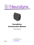
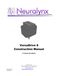
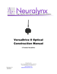
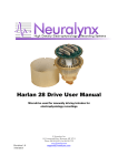
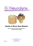
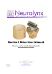
Tetrode Assembly Station
User Manual
Revision 2.4
1/28/2013
TAS_Manual
Page 1
Table of Contents
1
2
3
4
5
Document Overview ................................................................................................... 3
Tetrode Assembly Station Overview .......................................................................... 3
Unpacking ................................................................................................................... 4
Assembling the Tetrode Station .................................................................................. 5
Making Tetrodes ......................................................................................................... 6
5.1 Preparation ........................................................................................................... 6
5.2 Storage .................................................................................................................. 7
5.3 Assembly .............................................................................................................. 7
5.3.1 Cutting and Securing Wires .......................................................................... 8
5.3.2 Winding and Bonding Wires ...................................................................... 11
5.3.3 Finishing Up................................................................................................ 13
6
Testing and Plating ................................................................................................... 14
6.1 Shorts .................................................................................................................. 14
6.2 Continuity ........................................................................................................... 15
6.3 Final Cut ............................................................................................................. 15
6.4 Plating................................................................................................................. 16
List of Figures and Tables
Figure 3-1 Components of the Assembly Station ............................................................... 4
Figure 4-1 Side View of Tetrode Station ............................................................................ 5
Figure 5-1 Wire Holder ....................................................................................................... 6
Figure 5-2 Storage Box ....................................................................................................... 7
Figure 5-3 Tetrode Wire Placement and Cutting ................................................................ 8
Figure 6-4: Tetrode Placement on Stereotaxic Rod ............................................................ 9
Figure 5-5 Tetrode Wire Clip ........................................................................................... 10
Figure 5-6 Correct Wire Length and Tension ................................................................... 11
Figure 5-7 Heat Gun ......................................................................................................... 12
Figure 6-1 Delrin Plating/Rinsing Towers ........................................................................ 15
Figure 6-2 Delrin Towers.................................................................................................. 16
Revision 2.4
1/28/2013
TAS_Manual
Page 2
1 Document Overview
This document will give an overview of all setup procedures for the Tetrode Assembly
Station. It will outline all parts that should be included in the packaging, set up, and
manufacturing procedures for making tetrodes.
Disclaimer:
All techniques presented in this manual are compiled through research which is based on our
experience in different labs. Many labs have their own tetrode assembly procedures. This
manual should be used as a starting point only. If you have any questions when making your
tetrodes, please contact Neuralynx. Feedback and suggestions are welcome. They can help us
continue to improve this document.
Note:
For information on the Tetrode Spinner 2.0, please go to www.neuralynx.com and download
the newest version of this manual.
2 Tetrode Assembly Station Overview
The Tetrode Assembly Station is a tool to help you in creating your own tetrodes. This
device will allow you to customize each tetrode with specific lengths and twists. The
following document is a full comprehensive overview on how to make a tetrode, plate,
and later load into a microdrive.
Revision 2.4
1/28/2013
TAS_Manual
Page 3
3 Unpacking
Before assembly, unpack the assembly station parts and verify that all are present. Your
Tetrode Assembly Station contains the following:
Figure 3-1 Components of the Assembly Station
1. Station Base (16” x 36”) - Mounts
all equipment from the station base.
Printed ruler for measuring the
lengths of the tetrodes.
2. Delrin Plating / Wash Unit - For
plating and washing tetrodes.
3. Suspension Bar for Plating - Allows
user to move an EIB up and down
into plating solution.
4. Suspension Bar Holder - Holds the
24” support rod.
5. Motorized Tetrode Wire Spinner Automatically adjustable spinning
device counter. For more
information on the Motorized
Tetrode spinner please refer to the
Tetrode Spinner 2 User Manual.
6. Adjustable Angle Brackets Supports to hold the Suspension bar
Revision 2.4
1/28/2013
for plating and the suspension bar for
making tetrodes
7. 24” Support Rod - This rod supports
all adaptive equipment.
8. Suspension Bar for Making
Tetrodes - Allows you to loop the
tetrode wire through grooved end to
hold the wire in place while spinning.
9. Tetrode Wire Holder - Holds full
spool of tetrode wire.
10.
11.
12.
13.
14.
15.
-Not ShownHeat Gun
Magnifying Glasses
Tetrode Cutting Scissors
Syringe
Rinse Containers
Plastic Boxes
TAS_Manual
Page 4
4
Assembling the Tetrode Station
1. Clear an appropriate sized horizontal work surface for construction of the tetrodes.
This should be done in a low traffic area of the lab, away from doors, dust, debris
sources and fume hoods in particular.
2. Place the station base in your work area with the wire holder to the left and the
suspension bar holder in the back middle. Unit has non-slip feet on bottom side
than can be adjusted slightly if surface is not completely level.
3. Screw threaded rod into base (the suspension bar holder). Use a wrench for
secure mounting.
4. Attach suspension bar to threaded rod using thumb screw. The height depends on
the desired tetrode length.
5. Place tetrode spinner with center of rotation directly under the small notch in the
top of the metal portion of the suspension bar.
Figure 4-1 Side View of Tetrode Station
Revision 2.4
1/28/2013
TAS_Manual
Page 5
5
Making Tetrodes
5.1 Preparation
1. We recommend that you wash and dry your hands before handling tetrode wire or
the wire spool.
2. Open the wire dispenser (Figure 4-1) and remove tetrode wire from its box,
locating the wire end.
Figure 5-1 Wire Holder
3. Insert spindle into hole on outside of wire dispenser, through center of tetrode
wire spool and out hole on other side of wire dispenser. Bar should protrude
evenly out both sides. Tetrode wire should come off the bottom of the spool.
4. Slowly unwind a strand of wire to begin by applying light, even tension on the
wire end, while rotating spindle. Spool can rotate on the spindle freely, but
rotating the spindle as well keeps the tension from breaking or overstressing the
wire.
5. Press the end of the wire down onto a piece of double-stick or paper tape placed
just outside the dispenser to secure it. Close dispenser and leave closed to protect
the remaining unused wire.
Revision 2.4
1/28/2013
TAS_Manual
Page 6
6. Because a typical tetrode wire is quite small and can be difficult to see, we
recommend setting up your tetrode station in front of a white wall. You could
also secure white paper behind the spinner / suspension bar area.
5.2 Storage
Before making tetrodes, you need to have a safe place to store them. Two plastic boxes
are provided with the station. Fold a piece of paper so that it has a ridges to support the
tetrodes and make them easier to pick up later, place it in the plastic boxes(Figure 5-2).
Figure 5-2 Storage Box
Closing the lab doors and hoods before beginning is a good idea to reduce drafts that can
catch tetrode wire during the construction process.
5.3 Assembly
There are many different ways to make tetrodes. Each procedure depends on the desired
length of the tetrodes and the type of tetrode wire.
Revision 2.4
1/28/2013
TAS_Manual
Page 7
5.3.1 Cutting and Securing Wires
1. Take the end of the tetrode wire between the thumb and middle finger of your
right hand and pull it out along the surface of the station base with slow, even
tension, while slowly rotating the spindle with left hand to match the speed of the
wire leaving the spool.
2. Pull wire out to about the 45-50cm mark on the right hand side of the station base
for standard size tetrodes, long enough for loading a hyperdrive with 1cm travel.
(Feel free to make the tetrode longer [e.g. 55cm] to give yourself more working
room. You will be cutting them down to size in the end.)
Try to keep some tension on the wire at all times so it doesn’t wrap back up the spool, but
do turn the spindle handle to let out more wire.
50-55cm
If the end of the wire is all curled up then it has sprung back from too much tension. Cut
off the curled part with the tetrode scissors and discard. Don’t worry if the wire springs
back a little bit when you let it go – slow curves are just fine and will straighten out
during the wrapping/heating phase, kinks and very tight curls will not.
Figure 5-3 Tetrode Wire Placement and Cutting
3. Press the wire down onto the paper or double-sticky tape in front of the dispenser
opening to hold the end for the next wire. Don’t worry about the tip of the wire
getting oily or sticky – you’ll be cutting it off and discarding it soon. Using the
tetrode scissors, make a swift and sharp cut just after the point where the wire was
stuck down.
Revision 2.4
1/28/2013
TAS_Manual
Page 8
4. Take one end of the wire between the thumb and middle finger of each hand, fold
the wire in half and bring the two ends together. Hold both free ends with one
hand. Cut loop at the bottom with the tetrode scissors to make two equal length
pieces.
5. Take the two cut ends with the other hand and gently wrap the wire over the
adjusting bar so that two wires go down each side of the bar. The metal piece of
the bar has two small notches on the top to hold the wire in place. Place each
loop into its own notch. This will hold them in place during wrapping while the
wires from bonding above the twist.
Figure 6-4: Tetrode Placement on Stereotaxic Rod
6. Take all four ends together between two fingers at the bottom, applying very light
tension to keep the wires on the bar. If the wires are not tight together at the
bottom, you can spin the portions that protrude below where you are holding it
with your fingers to get them to hold together.
Place all four ends, as vertically as possible, in the middle of the spinner clip. The
clip should hang directly down not favoring one side or the other.
Revision 2.4
1/28/2013
TAS_Manual
Page 9
Figure 5-5 Tetrode Wire Clip
Reconfirm that all four wires are in the notch in the adjustment bar at the top. Let the
spinner clip hang free. There should be tension on all four wires. If you see any wire
diverging from the others (Figure 5-6), it has not been caught by the clip or is not the
correct length. Readjust and re-clip until all four wires are straight. The clip should float
on top of the Delrin piece with the two embedded magnets (with the new Tetrode Spinner
2.0, there will guide posts to help you align this process.) Please note that with the new
Tetrode Spinner 2, the receptacle that houses the clip is slightly different. All techniques
thus far are the same. For further information, please refer to the Tetrode Spinner 2.0
User Guide.
Revision 2.4
1/28/2013
TAS_Manual
Page 10
Figure 5-6 Correct Wire Length and Tension
7. Place clip with wire ends in the holder on the tetrode spinner. The clip should
hang down freely without resting on the sides or bottom. The middle of the clip
should be positioned directly above the center of the spinner for even winding.
5.3.2 Winding and Bonding Wires
1. Turn spinner switch to “Right” to begin winding in the forward direction. At
approximately 1 revolution per second, the clip should turn smoothly and evenly
without significant wobble. If the clip wobbles, stop spinning and reposition the
clip or spinner base. (If you are using the new Tetrode Spinner 2.0, please refer to
user’s manual for complete instructions on how to operate the spinner.)
Wind wire in forward direction for approximately:
• 90 turns for a 55cm initial length tetrode wire
• 80 full turns for a 50cm wire
• 60 turns for a 40cm wire
Stop spinner when finished.
Revision 2.4
1/28/2013
TAS_Manual
Page 11
2. Turn switch to “Left” position. Unwind wire to relieve rotational tension for half
as many turns as it was wound in the forward direction. For example, if you
wound 80 turns in the forward direction for a 50cm wire, unwind about 40 turns
in reverse.
Figure 5-7 Heat Gun
3. When Using Platinum Iridium wire with HML VG Bong Coating:
HML is a Heavy Polyimide and the VG is a bond coat that is coated on top of the
polyimide. The bonding temperature of the VG Bond Coat is 180-200 degrees
Celsius. The maximum temperature that should be used for the Polyimide is 240
degrees. These temperatures should not be exceeded at a close range. The heat
gun has two settings, a high (585 C) and a low position (400 C).
When using the VG bond coat, use the low position and have the gun a few
centimeters away from the wire. (Using a heat higher than this will cause a rapid
Revision 2.4
1/28/2013
TAS_Manual
Page 12
heating of the HML. This could cause micro holes in the insulation which will
lead to cross-talk between the wires.)
4. With the tip of the heat gun approximately 1-2 cm away from the wires, heat
ONLY the straight part of the wire bundle. Take about five seconds to heat from
beneath the loop down to the clip. Be sure to heat right down to the clip so the
individual wires don’t splay out at the ends after being cut.
5. Move up and down your wire at an even rate making sure to heat evenly on all
sides of the tetrode wire. Move the heat gun up and down the wire at a steady
rate with a medium flow. This should give the outside of the HML sufficient heat
to bond together. Do this at three different angles for roughly 5 seconds.
5.3.3 Finishing Up
1. After the wire insulation is melted, cut the tetrode just above the clip with the
tetrode scissors.
2. Carefully lift the tetrode off the adjusting bar and place it in your tetrode storage
box.
3. Open the clip and discard the small remaining end pieces. You do not need to
separate the wires or strip the insulation off the ends at this point. That is usually
best done just before loading of the microdrive.
4. Close your tetrode storage box and start the next tetrode.
A good tetrode is stiff and straight with a small oval loop of no more than 1-2 cm in
diameter. The tip should look like one solid wire, even under magnification. If there are
any splits at the end or along the way, the tetrode should be discarded.
If any tetrode wires break or curl up during the procedure, discard the tetrode. It does not
matter how expensive the wire is – it is never worth trying to use a broken or
questionable tetrode!
In general, it is a good idea to make twice as many tetrodes as you think you need.
Usually, the next step in this process is loading of the microdrive. For specifics in
loading Neuralynx drives, please refer to the NLX 5,9,18 User Manual and the
Revision 2.4
1/28/2013
TAS_Manual
Page 13
VersaDrive User Manual. After you have completed loading your particular microdrive,
continue to Section 6, Testing and Plating.
6 Testing and Plating
It is always good practice once a drive is loaded to test all connections for continuity and
for short circuits before implanting the device. For this testing, you should mount your
drive securely in a micromanipulator or custom drive holder (available soon from
Neuralynx).
*CAUTION* The testing and plating phase is the most vulnerable time for a tetrode and
the microdrive. The drive should always be held or mounted securely. You should
always be aware of where tetrodes are protruding from the bottom of the drive and how
you are holding the microdrive.
6.1 Shorts
To test for shorts, connect each pair of individual wires across an impedance meter.
Impedance meters checks impedance by outputting a small, say 1nA current, sine wave at
a relevant frequency, say 1 kHz. (Pure resistance is not a good test of electrodes, and
doesn’t actually relate well to their ability to transmit biological signals). One systematic
way to check all possible pairs is to put one lead of the impedance tester in a hole in the
EIB top connector, then put the other lead in all remaining holes and test one by one. If
you have a connection of less than 5 Megaohms, you have a short (or you touched the
leads together!)
If you have a short, it is probably at the top where the wires are loaded. Look for
exposed wires touching each other. Remember that a few of the connections such as the
grounds on each headstage are connected to the EIB itself.
If the impedance measured is in the Megaohms range, the short is most likely at the
bottom (un-plated tetrode impedance is approximately 2-3 Megaohms). In this case, it is
probably just some extra debris on the tip of the tetrode. Snip off the very end and make
sure it is completely dry before checking again.
Revision 2.4
1/28/2013
TAS_Manual
Page 14
6.2 Continuity
Once you have determined that there are no shorts, you must test each channel for
continuity.
1. Fill the cups in both Delrin towers of the Plating/Wash Unit with water.
Figure 6-1 Delrin Plating/Rinsing Towers
2. Slowly and carefully lower the drive by hand, with tetrodes extended, until the
tips of the tetrodes to be tested, but not the tip of the microdrive, is clearly in
the water in the plating side. The plating side is the one with the stainless steel
lead exiting the bottom.
3. Connect one probe of the impedance tester to the plating side lead, and alternate
touching the other to the connections on top of the EIB to test for continuity. Any
finite impedance confirms continuity. (readouts will differ with impedance
testers)
4. Be sure that tetrode tips are in the water. Test individually to be sure. Record
which wires fail the continuity test.
When all continuity testing is done, raise the drive and let it dry for at least 25 minutes.
Water in the drive tip will cause shorts.
6.3 Final Cut
When you have confirmed that all tetrode wires are continuous, it is time to cut the
tetrodes. Cut each tetrode down to where they just pull into the drive tip with the drives
screwed all the way up. One way to do this is to lower all the drives down a set amount,
such as 3 mm, and make one clean cut across all the wires 3mm from the drive tip.
This “final cut” is best done by holding the drive horizontally in one hand, and the tetrode
scissors in the other. Holding one blade still and ‘chopping’ down in a swift, smooth
Revision 2.4
1/28/2013
TAS_Manual
Page 15
motion with the other usually works best for cutting all tetrodes without bending them. If
you like you can do them one at a time. A final cut can also be made with a sharp scalpel.
Neuralynx recommends discarding the scalpel after using it for a single cut. The blade
must be as sharp as possible.
Once you’ve made the final cut, you can either begin plating or bring the tetrodes up into
the drive by holding the drive upside down and screwing the drive screws up one at a
time until the tetrodes just go into the drive tip. The closer you can get the tetrodes to the
end of the drive, the better you will know the depth to which you are in brain later on.
6.4 Plating
The last stage of microdrive preparation before implantation is to plate the ends of the
tetrode wire with Plating Solution. This reduces tetrode impedance and, more
importantly, tip capacitance between the tetrode wire and brain. Platinum Black and Gold
Plating Solution can be purchased separately from Neuralynx.
Figure 6-2 Delrin Towers
This stage proceeds similarly to the testing phase, but now the plating Delrin tower cup is
filled with Plating Solution. Tetrodes can be plated individually or in groups.
For each channel, alternate between impedance testing and running negative current
through each wire (approximately 2 µA works well). You want to plate each channel
down to about 200-300kΩ impedance. If you do over-plate and short the wires, you can
either cut the end of the tetrode (shortening it, unfortunately) or reverse the direction of
the current for 20 seconds or so to blow off the plating and start again.
If an electrode will not plate, reversing the current or cutting off the very end can also be
an effective remedy. Replacing the whole tetrode works too.
It is also important to note that recent findings and research have been done with
additives. This can greatly reduce the impedance from 200-300k to down below 100k. If
you would like more information on these methods, please contact
[email protected].
*IMPORTANT* After plating each tetrode, wash off the excess plating solution by
dipping it in the water filled Delrin tower cup.
Revision 2.4
1/28/2013
TAS_Manual
Page 16
The point of having two towers is to remind you to do this step. After washing, let the
tetrode dry for about 25 minutes before retracting the tetrodes back into the drive.
If you accidently pull plating solution up into the drive tip, it will dry up and leave a
sticky residue that will prevent your tetrodes from being able to move out of the drive.
After all channels of all tetrodes are plated, washed and dried, it is a good idea to check
for shorts caused by over plating. If you find shorts between tetrodes where you didn’t
before, the tips are probably still wet.
Plating is best done on the day of surgery. Though most tetrodes will stay plated over
time, some do not. If left unused overnight or longer, Neuralynx recommends retesting
your tetrodes as close to surgery as possible.
Pull the tetrodes to just inside the drive and start getting ready for surgery!
Revision 2.4
1/28/2013
TAS_Manual
Page 17