1
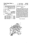
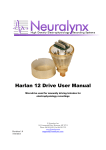
VersaDrive Construction Manual 4 Tetrode VersaDrive Neuralynx, Inc. 105 Commercial Drive, Bozeman, MT 59715 Phone 406.585.4542 • Fax 866.585.1743 www.Neuralynx.com Revision 2.3 5/24/2013 [email protected] Contents 1. 2. 3. 4. 5. 6. 7. 8. 9. 10. Introduction to VersaDrive Designs……………………………………….... 3 Organization of the Manual………………………………………………… 4 Document Revision History ………………………………………………... 4 Parts list for 4 tetrode VersaDrives…………………………………………. 5 Description of the 4 tetrode VersaDrive….…………………………………. 6 Assembling the tetrode carriers………..……………………………………. 7 Figure 1.1 Tetrode carrier parts Figure 1.2 Inserting the tetrode guide tubes Figure 1.3 Arrangement of guide tubes and shuttles Figure 1.4 Gluing a guide tube to a shuttle Assembling the lower stage………………………………………………….. 12 Figure 2.1 Top view of the base Figure 2.2 Bottom view of the base Figure 2.3 View of the enclosure Figure 2.4 Diagram of an entire tetrode drive Figure 2.5 Inserting a tetrode carrier into the base Figure 2.6 Adding a drive pin to the first tetrode carrier Figure 2.7 Placement of the 4 tetrode carriers Figure 2.8 Attaching the enclosure Figure 2.9 Inserting 1 of the drive screws Figure 2.10 Raising a carrier to facilitate tetrode loading Figure 2.11 Lower stage ready for tetrode loading Figure 2.12 After loading one tetrode Assembling the connector…….…………………………………………….. 24 Figure 3.1 Top view of Cap Figure 3.2 Bottom view of Cap Figure 3.3 Inserting ground wires from below Figure 3.4 Securing ground wires with receptacles Figure 3.5 Insertion of wires of 1 tetrode into cap Figure 3.6 Top view of pin-out for implant connector Figure 3.7 Attaching the cap to the lower stage Figure 3.8 Lowering a tetrode carrier to allow slack in the wires Figure 3.9 Stripping and connecting wires with receptacles Figure 3.10 Inserting the inner pins and clipping all pins Figure 3.11 Raising the tetrode carriers to their ready-to-go position The 4 tetrode VersaDrive…………………………………………………….. 35 Figure 4.1 A finished 4 tetrode VersaDrive Figure 4.2 Standard exit hole pattern Glossary……………………………………………………………………… 37 Revision 2.3 5/24/2013 VersaDrive 4 Construction Manual Page 2 VersaDrive Overview VersaDrives are small animal implants useful in a wide range of neuroscientific work. In their simplest embodiment, VersaDrives are designed for tetrode recordings from a single brain structure or from two or more structures that fall on one line that extends from the skull surface into the depths of the brain. Even this first type, however, has variants: VersaDrives with 2, 4, 8, 16 and 32 independently moveable tetrode drives are available. In more complex cases, the tetrode exit holes for VersaDrives are arranged to target brain structures whose locations are not co-linear. Examples include implants aimed at two portions of medial entorhinal cortex plus the dorsal hippocampus and implants that allow bilaterally symmetric placement of tetrodes into the anterior thalamic nuclei. Different numbers of tetrodes are also possible for these more elaborate drives. VersaDrives can be used for electrical brain stimulation and for liquid injections as well as recordings. For instance, injections can be made into a recorded structure without disturbing the activity of identified single cells. A separate implant class allows infrared diffuse optical tomography, enabling simultaneous measurements of oxyhemoglobin and deoxyhemoglobin in freely moving rats; such measurements can be combined with EEG recordings with currently available models. We also anticipate models that allow fiber optic bundles to be placed in brain areas previously modified to express channel rhodopsin, opening up new ways to activate or suppress activity. In short, VersaDrives are versatile and new designs can be realized based on the requirements of individual investigators. Nevertheless, the job of constructing actual implants from the supplied components is quite simple. This manual contains a detailed description of the process by which a basic model, the 4 tetrode VersaDrive is assembled. It is also the starting point for understanding how more elaborate types are put together. If you are about to begin construction of a different model, you will find not one but two lists + pictures of the implant parts, one so you can follow the steps for a 4 tetrode implant and one for your specific implant. In the second case, we have also provided diagrams for steps, in our judgment, differ in important ways from similar steps for the 4 tetrode drive. In any case, if more help is needed, please write to: [email protected] and we will work with you to solve the problem. Revision 2.3 5/24/2013 VersaDrive 4 Construction Manual Page 3 Organization of the manual The purpose of this manual is to help you assemble and load 4 tetrode VersaDrives. The manual is divided into 5 sections. It starts with a parts list with pictures and names of the drive components. Next you will see how to put together tetrode carriers which are the subassemblies that hold the recording tetrodes and allow them to be moved gradually into the brain. In the third section, the carriers are installed in the lower stage of the VersaDrive. The lower stage is composed of the base, the enclosure, 4 of 8 drive pins that hold the shuttle carriers in place and 4 drive screws. When this installation is complete, the tetrodes can be loaded into their carriers. Fourth, the tetrode wires are threaded through the cap, the receptacles (electrical connector contacts) are pushed into the cap and the cap is attached to the lower stage with the first set of pins and a second pin set so that the entire implant is locked together. Finally, the pins and tetrodes are trimmed and the implant is stored for use during surgery. In preparation for beginning the assembly process, the user should look at the parts list on page 5 and become familiar with the overview presented on page 6. The figures that make up most of the manual are meant to be reasonably self-explanatory so that the text for each step during construction is rather brief. In our experience with how people learn to build the 4 tetrode implants, you should not be surprised if you have problems with the first one or two. Nevertheless, the learning curve is not very steep, and after some practice, it should take less than 3 or 4 hours to make a single implant. You will also find that the time per implant is reduced if you build several together. Revision 2.3 5/24/2013 VersaDrive 4 Construction Manual Page 4 *Tetrodes not included Emery board (nail file) for sanding parts. *Guide Tubes not included Revision 2.3 5/24/2013 VersaDrive 4 Construction Manual Page 5 Description of the 4 tetrode VersaDrive The main components of the implant are the base, the enclosure and the cap. The base is the part mounted directly on the rat’s head, above the trephine hole that admits the tetrodes into the brain. The tetrodes (and possibly portions of the guide tubes, depending on how long you decide the tubes should be) extend through small exit holes in the bottom of the base and can be gradually lowered into the brain by turning the drive screws. The enclosure surrounds and protects all working parts of the implant and provides much of the structural strength of the completed device. The cap also strengthens the implant, but its main functions are to provide access to the drive screws and to form the connector by which electrical contacts are made between the tetrodes and grounds and the outside world. The drives in a VersaDrive are independently moveable. Each drive consists of a shuttle, a guide tube, 2 drive pins, a drive screw and a tetrode. In use, the shuttle rides down the drive pins as it is pushed by the drive screw. The pins ensure that the shuttle and guide tube move down and are not twisted by the screw motion. The drive pins serve a second, equally important purpose, namely, to clamp together the main components. Thus, key parts of the drives are also key structural components. An assembled VersaDrive is shown in Figure 4.1. A single drive, suspended by invisible support structures, is shown in Figure 2.4. You might look at these diagrams to get a notion of how the essential aspects of a VersaDrive are arranged and how a drive actually works. Revision 2.3 5/24/2013 VersaDrive 4 Construction Manual Page 6 Part 1 Assembling the tetrode carriers Revision 2.3 5/24/2013 VersaDrive 4 Construction Manual Page 7 Figure 1.1. Components of the tetrode carrier. The tetrode carrier consists of a shuttle and a guide tube. The shuttle is a plastic piece with 4 predrilled holes. The smallest hole accepts the guide tube that will later house the length of the tetrode. The tube serves to guide the tetrode into one of the exit holes at the bottom of the implant base. Two other holes will be filled with the drive pins that support the tetrode carrier and allow it to move down when the drive screw is turned. The drive screw will be turned into the final hole when the tetrode carrier is already in the base and at its lowest possible position. When the screw is initially turned in, it taps (creates a thread) in the drive hole and raises the tetrode carrier to its highest possible position. Later on, in use, the screw is turned in the opposite direction, lowering the carrier and therefore the tetrode into the brain. The guide tube is either a length of 34 gauge (0.184 mm outer diameter) stainless steel tubing or an equal length of 0.1XX mm diameter polymicro glass tubing. The length of the tubing depends on the brain target. For example, if the tetrodes are to record from the dorsal hippocampus, the guide should be 13 - 15 mm long. The decision about which material to use should have been made at purchase time. In some cases, we will supply enough of whichever tubing type you selected and it will be up to you to cut the lengths. If you are to do the cutting, we will send a separate instruction manual. We also will supply cut lengths of the chosen guide tubing at some additional cost. Revision 2.3 5/24/2013 VersaDrive 4 Construction Manual Page 8 Figure 1.2 Inserting the guide tubes into the shuttles. There are two preliminary steps for this operation. First, when the shuttles are clipped from the manufacturing frame the cut attachment points will be jagged. To ensure that these protrusions do not interfere with tetrode carrier movements, they must be abraded away with the included emery board. The same cloth should be used to slightly roughen 2 mm of the guide tube. This is done to provide enough friction so that the tube does not slip out of the hole after insertion. In constructing the carriers, the starting materials are 4 identical shuttles and 4 identical guide tubes, but the goal is to build two pairs of mirror symmetric tetrode carriers. The reason for this pairing is very simple: the members of each pair face each other across the midline of the VersaDrive, as shown in Figure 2.7 (and later figures). To emphasize the fact that the products are not the same, Figure 1.2 shows two guide tubes being inserted from above (red arrows) and two from below (black arrows). For both types, the tubes should be pushed through so that 0.5 mm of the roughened ends wind up protruding. Revision 2.3 5/24/2013 VersaDrive 4 Construction Manual Page 9 Figure 1.3 Diagram of the nearly finished tetrode carriers with a short length (0.5 mm) of each guide tube extending beyond the shuttle surface opposite to the side from which it was inserted. Revision 2.3 5/24/2013 VersaDrive 4 Construction Manual Page 10 Figure 1.4 Gluing the guide tube to the shuttle to complete a tetrode carrier. We recommend 5 minute epoxy. Super glue (cyanoacrylate) should not be used. Revision 2.3 5/24/2013 VersaDrive 4 Construction Manual Page 11 Part 2 Assembling the lower stage Revision 2.3 5/24/2013 VersaDrive 4 Construction Manual Page 12 Figure 2.1 Figure 2.2 Two views of the implant base. Figure 2.1 shows the base in the orientation for assembly. The upside down picture in Figure 2.2 shows the peg that is set above the trephine hole in the animal’s skull and the exit holes for the guide tubes and tetrodes. Visible in both views are 8 holes for the pins that hold the implant together and act as supports for the tetrode drives. The 8 holes are organized into 4 pairs consisting of an inner hole and an outer hole; each pair is part of a single drive. Revision 2.3 5/24/2013 VersaDrive 4 Construction Manual Page 13 Figure 2.3 View of the implant enclosure. This piece will sit above the base (Figures 2.1, 2.2) to shield the moving parts of the implant and to provide part of the support for the tetrode drives. The enclosure has two types of holes. The first 8 hold the tetrode drive pins; these holes line up with the holes in the base (and similar holes in the cap – see Figure 3.1 and Figure 3,2). The second set of 4 holes provides access to the heads of the drive screws. The large rounded rectangle in the middle is for access to the drives during assembly. Revision 2.3 5/24/2013 VersaDrive 4 Construction Manual Page 14 Figure 2.4 Components of a drive. Figure 2.4 shows the working parts of a single drive as if they were held in the correct supporting structure (base, enclosure, cap). During use, when the screw turns, the shuttle is pushed downward along the pins. The rigidly coupled guide tube moves in the same way. If a tetrode were mounted in the tube, its tip would also move down, into the brain. With the 1 mm diameter screw, one complete turn pushes the moveable parts down by 0.25 mm (250 µm). The maximum practical travel of the moveable parts from initial to bottom-most position is 3.5 mm. Revision 2.3 5/24/2013 VersaDrive 4 Construction Manual Page 15 Figure 2.5 Inserting one of the tetrode carriers into the appropriate exit hole in the implant base. Note the orientation of the carrier shuttle requires that the correct type of carrier (Figure 1.2, 1.3) is used. The tetrode guide tube is shown here as straight, but when the support rails are in place the tube will assume a curved shape that bends from the top of the shuttle to the exit hole. Revision 2.3 5/24/2013 VersaDrive 4 Construction Manual Page 16 Figure 2.6 One tetrode drive partly assembled. This condition is reached by pushing a rail (insect pin) into the appropriate outer rail hole in the base. Since this is a press fit, you must expect resistance. Push the pin up until 5.0 mm protrudes from the base. Next, push the outer rail hole of the shuttle onto the pin tip. With the pin fixed relative to the base, push the shuttle of the tetrode carrier down until it is flush with the top of the base. Next, push the pin through both the base and shuttle until its tip is 15 mm above the top surface of the base; the total protrusion should be 15 mm. Now, repeat the process outline just above for the other 3 tetrode carriers + outer rail pins. After these steps, the implant should look as drawn in the next Figure. Revision 2.3 5/24/2013 VersaDrive 4 Construction Manual Page 17 Figure 2.7 Implant with all 4 tetrode carriers in place, oriented and partially supported by the outer rails. At this point, the implant is ready for the enclosure to be placed above the partly completed drives. Revision 2.3 5/24/2013 VersaDrive 4 Construction Manual Page 18 Figure 2.8 Attach the enclosure to the base by pushing the tips of the outer rail pins through the correct holes in the enclosure. The enclosure is drawn with a cutout to reveal the partly finished drives. The bottom edge of the enclosure will surround the outside edge of the base. The press fit between the enclosure and the base is one of the strengthening features of the implant. Revision 2.3 5/24/2013 VersaDrive 4 Construction Manual Page 19 Figure 2.9 Building a drive. Insert one of the supplied 1 mm by 5 mm machine screws into drive screw hole in the enclosure and turn down until its tip enters the drive screw hole in the shuttle of a tetrode carrier. To get the proper alignment for threading, it may be necessary to adjust the position of the tetrode carrier shuttle by manipulating the outer drive pin. If you continue to press on the screwdriver while turning, the screw will tap a thread in the shuttle hole. Additional turning will cause the tetrode carrier to rise inside the enclosure. Continue to turn until the top of the shuttle is just flush against the undersurface of the enclosure’s top. Now, repeat screw insertion for each of the other 3 drives. This step accomplishes two things. First, it brings the guide tube tops to just below the top of the enclosure, making it convenient to load the tetrodes into the tubes. Second, it puts the tetrode carriers into “what would be” the correct starting positions to lower the tetrodes into the brain. “What would be”? Yes! In later steps, the carriers will be lowered to their bottom-most position (during insertion of the receptacles) and finally raised back to its highest position (for actual use). Revision 2.3 5/24/2013 VersaDrive 4 Construction Manual Page 20 Figure 2.10 A tetrode carrier in the process of being raised by its drive screw into its upper position. This elevated position bring the guide tube into the rounded rectangular window in the middle of the enclosure where it is easy to load with the tetrode. Revision 2.3 5/24/2013 VersaDrive 4 Construction Manual Page 21 Figure 2.11 Implant ready for inserting the tetrodes into the guide tubes of the carriers. The tetrodes are prepared according to instructions in a separate manual or according to procedures used in your laboratory. Note the exposed tops of two tetrode guide tubes which are visible through the opening in the enclosure. As mentioned in Figure 2.10, their position at the top of the enclosure makes it easier to load the tetrodes. Revision 2.3 5/24/2013 VersaDrive 4 Construction Manual Page 22 Figure 2.12 Implant with one tetrode threaded through its guide tube. To arrive at this state, the twisted portion of the first tetrode is inserted into the top of a guide tube and pushed down until the free (i.e., non-twisted) portions of the 4 tetrode wires are at the upper opening of the guide tube. When this is done, the twisted end of the tetrode will (of course) extend out of the exit hole at the bottom of the peg. Next, use super glue (cyanoacrylate) to bond the tetrode into the guide tube opening. This completes the mounting of the first tetrode. The same steps are repeated for the other 3 tetrodes. This completes construction of the lower stage. Revision 2.3 5/24/2013 VersaDrive 4 Construction Manual Page 23 Part 3 Assembling the Connector Revision 2.3 5/24/2013 VersaDrive 4 Construction Manual Page 24 Figure 3.1 Figure 3.2 Top (Figure 3.1) and bottom (Figure 3.2) views of the implant cap. The 18 holes in the center ridge will form the electrical connector when the 2 ground wires and 16 tetrode wires are in the holes and the receptacles are forced in to secure the wires. In the top view, two drive screw holes and two pin hole pairs are seen in front of the ridge; in the bottom view, all the holes are visible. Note the retainer around each screw hole; with the cap in place, the screw head is pressed against the smaller hole in the enclosure so the screw can turn but not move up or down. Revision 2.3 5/24/2013 VersaDrive 4 Construction Manual Page 25 Figure 3.3 Figure 3.4 Installing ground wires. In Figure 3.3, two ground wires with the insulation stripped from their ends are inserted from the bottom into the middle two receptacle holes of the cap. Two goldcolored receptacles are shown poised above the cap. In Figure 3.4, the receptacles are about to be forced into the holes with the wires ready to be locked into place. Revision 2.3 5/24/2013 VersaDrive 4 Construction Manual Page 26 Figure 3.5 Wiring the cap. With the ground wires in place, the next step is to send the wires from each tetrode through the selected holes in the cap. Figure 3.5 shows how the wires from a single tetrode were put into 4 adjacent holes using very fine forceps. To complete this step, the wires from the other 3 tetrodes are placed in the correct holes in the cap. Revision 2.3 5/24/2013 VersaDrive 4 Construction Manual Page 27 Figure 3.6 Pin connections for a 4 tetrode VersaDrive. This is a top view of the cap “ridge” showing the 18 holes into which receptacles are press-fit. The 4 tetrodes are labeled 1, 2, 3 and 4 where each has the suffixes A, B, C and D. G1 and G2 are ground connections; G1 is the panel ground; G2 may be used as the recording reference. In practice, G1 and G2 are attached to the skull screws to which the implant is bonded with dental cement. The pin connections shown in Figure 3.7 are appropriate for Neuralynx connector HS-18 millmax. If you are using a different connector, you must reorganize the pin-out appropriately. Revision 2.3 5/24/2013 VersaDrive 4 Construction Manual Page 28 Figure 3.7 Installing the cap. With the tetrode wires running through the connector holes in the cap, position the cap over the 4 drive pins protruding from the lower stage; the correct rail holes in the cap should line up with the tips of the drive pins. Push the cap down until it touches the drive screw holes. Revision 2.3 5/24/2013 VersaDrive 4 Construction Manual Page 29 Figure 3.8 Slackening the tetrode wires. This step requires a bit of explanation. If the tetrode wires were captured in their holes when the tetrode carriers were in their upper-most position (as they would be without this step), turning the drive screws would quickly break the wires. It is therefore necessary to put slack into the wires so they remain intact while the tetrodes are driven into the brain. So, to provide slack, hold the cap in place and turn each drive screw until its tetrode carrier is at the bottom position. The process of lowering the tetrode carriers is indicated by the red arrow above the yellow shuttle on its way down. Note that this extends one of the tetrodes below the others. Revision 2.3 5/24/2013 VersaDrive 4 Construction Manual Page 30 Figure 3.9 Completing the connector. Push a trimmed receptacle into each tetrode wire hole. The insertion of a receptacle strips the insulation from the wire, establishes the electrical contact and captures the wire in the hole. Now, if necessary, trim the wires as close to the tops of the receptacles as possible. Note that receptacle insertion may cut the wire without any need for trimming. Revision 2.3 5/24/2013 VersaDrive 4 Construction Manual Page 31 Figure 3.10 Finishing the drives. Push the inner drive pins into the holes in the caps and continue pushing until the tips go through the shuttles and the correct holes in the base. With the pins situated as drawn in Figure 3.10, they should be cut to make them flush with the plastic surfaces of the base and the cap; the result of clipping the pins is drawn in Figure 3.11. Revision 2.3 5/24/2013 VersaDrive 4 Construction Manual Page 32 Figure 3.11 Last steps. As described above, it is necessary to re-raise the drives back to their uppermost position, from which they will be lowered into the brain. Figure 3.11 shows one of the drives on its way back up. Of course, re-raising must be done for the other drives as well. The final task, not shown explicitly, is to trim the tetrodes to the length you will require to reach the brain structure of interest for your purposes. In the completed drive drawn in the last diagram (Figure 4.1) the tetrodes have been clipped to a (scaled) length that is about correct for an initial position above the CA1 layer of the dorsal hippocampus, assuming use of the stereotaxic system of Paxinosdri and Watson (6th Edition, 2005, Elsevier Academic Press). Revision 2.3 5/24/2013 VersaDrive 4 Construction Manual Page 33 Part 4 A complete 4 tetrode VersaDrive Revision 2.3 5/24/2013 VersaDrive 4 Construction Manual Page 34 Figure 4.1 Drawing of a 4 tetrode VersaDrive ready to be implant on the head of a rat, a mouse or another small animal. The drive weighs 1.6 grams fully assembled and is easily carried by an animal as small as a mouse. This model and ones with different exit hole arrangements (see Figure 2.2) allow stable, low noise recordings from one or more brain structures. We hope that this manual made the job of putting together your first drive reasonably easy, but if some of the steps are unclear, please write to us and we will try to provide additional explanations. Of course, if there are errors or problems in the current manual we will make appropriate modifications in future versions. Revision 2.3 5/24/2013 VersaDrive 4 Construction Manual Page 35 Figure 4.2 Drawing of the VersaDrive 4 standard exit hole pattern. The tetrode holes have diameters of 0.012 in (0.300 mm) with a spacing distance of 0.024 in (0.600 mm) center to center. Revision 2.3 5/24/2013 VersaDrive 4 Construction Manual Page 36 Glossary Base: Cap: Drive: Drive Pins Drive Screw: Enclosure: Exit Hole: Guide Tube: Lower Stage: Ridge: Peg: Receptacles: Shuttle: Tetrode: Revision 2.3 5/24/2013 Bottom-most of three structural implant parts; the others are the “enclosure” and the “cap”. The lowest part of the base is the “peg” which is located above the trephine hole via which tetrodes enter the brain. Top-most of three structural implant parts; the others are the base and the enclosure. The cap helps to support the drives. At the top of the middle “ridge” are holes properly space to form a standard Mill-Max connector when filled with receptacles. The working subassembly of an implant. Each independently movable drive carries a tetrode into the brain. A drive consists of a tetrode carrier, a drive screw and two drive pins. Drive components and their arrangement are depicted in Figure 2.4. Rails on which tetrode carriers move down, pushing the tetrode into the brain. Each drive has an inner drive pin and an outer drive pin, so named for the positions they occupy in the shuttle. Captive screw whose bottom inserts into a hole in a shuttle. Turning the screw drives a tetrode carrier and therefore a tetrode into the brain. The pitch of the 1.0 mm screws used in VersaDrives is 0.250 mm per turn. Middle of three structural implant parts; the others are the “base” and the “cap”. The enclosure shields the moving parts of the drives from external forces. The small hole at the bottom of the peg through which a tetrode leaves the drive and enters the brain. A Polymicro Glass tube that guides a tetrode from its top, above a shuttle, into an exit hole at the bottom of the base. Guide tubes may also be made of stainless steel hypodermic tubing. Subassembly that consists of the base, enclosure, outer drive pins and drive screws. Part 2 is devoted to describing its construction. Center portion of the cap that forms the electrical connector. The bottom of the base. The peg is a contoured cone that aims the tetrodes properly to enter the trephine hole in the rat’s skull. The exit hole are drilled through the peg. Electrical contact pins trimmed of their tails. When forced into a connector hole, the receptacle strips a tetrode wire and secures the wire in place. Moveable part that slides down drive pins by screw motion. Each shuttle holds a guide tube, inside of which sits a tetrode. 4 wire probe used to record multiple individual neurons, notably from the brains of freely moving rats and mice. Tetrodes are not included with the purchase of a VersaDrive VersaDrive 4 Construction Manual Page 37 Tetrode Carrier: Revision 2.3 5/24/2013 Subassembly that consists of a “shuttle” and a “guide tube”. Tetrode carriers are driven down inside the enclosure by screw motion, pushing the tetrodes into the brain. VersaDrive 4 Construction Manual Page 38