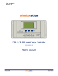
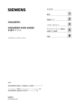
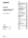
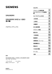
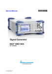
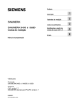
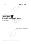
1
PUBLIC ADDRESS SYSTEM
OPERATION MANUAL
CLASS-D AMPLIFIER
T-1D120-1D240-1D350-1D500
CH1 STBY
T-1D120
CLASS-D AMPLIFIER
POWER
PROT
CLIP
24V DC
SIG
ON
OFF
T-2D120-2D240-2D350-2D500
CH1
T-2D120
CLASS-D AMPLIFIER
CH2
STBY
POWER
PROT
CLIP
24V DC
SIG
ON
OFF
T-4D120-4D240-4D350-4D500
T-4D120
CLASS-D AMPLIFIER
CH1
CH2
CH3
CH4
STBY
POWER
PROT
CLIP
24V DC
SIG
ON
OFF
Please follow the instructions in this manual to obtain the optimum results from this unit.
We also recommend that you keep this manual handy for future reference.
1. SAFETY PRECAUTIONS .............................................................................. .1
2. FEATURES....................................................................................................3
3. NOMENCLATURE AND FUNCTIONS
3 . 1 Front Panel T-1D120-1D240-1D350-1D500............................................................4
3 .2 Rear Panel T-1D120-1D240-1D350-1D500 ............................................................4
3.3 Front Panel T-2D120-2D240-2D350-2D500............................................................5
3.4 Rear Panel T-2D120-2D240-2D350-2D500 ............................................................5
3.5 Front Panel T-4D120-4D240-4D350-4D500............................................................6
3.6 Rear Panel T-4D120-4D240-4D350-4D500 ............................................................6
4. OPERATING INSTRUCTION...........................................................................7
5. WIRING INTRODUCTION ..............................................................................10
6 . APPLICATIONS ........................................................................................11
7 . BLOCK DIAGRAM....................................................................... ... .............12
8. OPERATING INSTRUCTIONS ................................................... ........... 13
9 . FAULT DETECTION ................................................... ......................... 13
10 . SPECIFICATIONS................................................... .......................... 14
11. DIMENSIONAL DIAGRAM ........................................ ........................... 17
1. SAFETY PRECAUTIONS
Be sure to read the instructions in this section carefully before use.
Make sure to observe the instructions in this manual as the conventions of safety symbols and messages
regarded as very important precautions are included.
We also recommend you keep this instruction manual handy for future reference.
Safety Symbol and Message Conventions
Safety symbols and messages described below are used in this manual to prevent bodily injury and property
damage which could result from mishandling. Before operating your product, read this manual first and
understand the safety symbols and messages so you are thoroughly aware of the potential safety
Indicates a potentially hazardous situation which, if mishandled, could
result in death or serious personal injury.
Indicates a potentially hazardous situation which, if mishandled, could
result in moderate or minor personal injury, and/or property damage.
When Installing the Unit
When Installing the Unit
Do not expose the unit to rain or an environment
where it may be splashed by water or other liquids,
as doing so may result in fire or electric shock.
Should the following irregularity be found during
use, immediately switch off the power, disconnect
Use the unit only with the voltage specified on
the unit.Using a voltage higher than that which
is specified may result in fire or electric shock.
operate the unit in this condition as this may cause
fire or electric shock.
If you detect smoke or a strange smell coming
from the unit.
If water or any metallic object gets into the unit
If the unit falls, or the unit case breaks
If the power supply cord is damaged (exposure
of the core, disconnection, etc.)
If it is malfunctioning (no tone sounds.)
the power supply plug from the AC outlet and contact
y our nearest ITC dealer. Make no further attempt to
Do not cut,kink otherwise damage nor modify the
power supply cord. In addition, avoid using the
power cord in close proximity to heaters, and never
place heavy objects - including the unit itself - on
the power cord, as doing so may result in fire or
electric shock.
To prevent a fire or electric shock, never open nor
remove the unit case as there are high voltage
components inside the unit. Refer all servicing
to your nearest ITC dealer.
Be sure to replace the unit's terminal cover after
connection completion. Because high voltage
is applied to the speaker terminals, never touch
these terminals to avoid electric shock.
Do not place cups, bowls, or other containers of
liquid or metallic objects on top of the unit. If they
accidentally spill into the unit, this may cause a
fire or electric shock.
Be sure to ground to the safety ground (earth)
terminal to avoid electric shock. Never ground
to a gas pipe as a catastrophic disaster may result.
Avoid installing or mounting the unit in unstable
locations, such as on a rickety table or a slanted
Do not insert nor drop metallic objects or flammable
materials in the ventilation slots of the unit's cover,
as this may result in fire or electric shock.
surface. Doing so may result in the unit falling
down,causing personal injury and / or property
damage.
1
SAFETY PRECAUTIONS
When Installing the Unit
When Installing the Unit
Never plug in nor remove the power supply plug
with wet hands, as doing so may cause electric
shock.
Do not place heavy objects on the unit as this may
cause it to fall or break which may result in personal
injury and/or property damage. In addition, the object
itself may fall off and cause injury and/or damage.
When unplugging the power supply cord, be sure
to grasp the power supply plug; never pull on the
cord itself. Operating the unit with a damaged
power supply cord may cause a fire or electric
shock.
Make sure that the volume ontrol is set to minimum
position before power is switched on. Loud noise
produced at high volume when power is switched
on can impair hearing.
When moving the unit, be sure to remove its power
supply cord from the wall outlet. Moving the unit
with the power cord connected to the outlet may
cause damage to the power cord, resulting in fire or
electric shock. When removing the power cord, be
sure to hold its plug to pull.
Do not operate the unit for an extended period of
time with the sound distorting. This is an indication
of a malfunction, which in turn can cause heat to
generate and result in a fire.
Do not block the ventilation slots in the unit's cover.
Doing so may cause heat to build up inside the unit
and result in fire.
Contact your ITC dealer as to the cleaning. If
dust is allowed to accumulate in the unit over a
long period of time, a fire or damage to the unit
may result.
Avoid installing the unit in humid or dusty locations,
in locations exposed to the direct sunlight, near the
heaters, or in locations generating sooty smoke or
steam as doing otherwise may result in fire or
electric shock.
If dust accumulates on the power supply plug or in
the wall AC outlet, a fire may result. Clean it periodically. In addition, insert the plug in the wall outlet
securely.
Due to product upgrades, while some of the
features and specification in the user manual
does not match the actual functions, sorry for
any inconvenience and thanks for your kind
understanding!
Switch off the power, and unplug the power supply
plug from the AC outlet for safety purposes when
cleaning or leaving the unit unused for 10 days or
more. Doing otherwise may cause a fire or electric
shock.
An all-pole mains switch with a contact separation of at least 3 mm in each pole shall be incorporated in
the electrical installation of the building.
2
2.FEATURES
1. High efficiency class D power amplifier;
2. Standard cabinet design(1.5U), humanized design, exquisite craft, all show high temperament;
3. Built-in active bandpass filter, filter out unwanted music signal effectively;
4. Balance signal input, 1/2/4x120W,240W,350W,500W power output;
5. Panel was regulating function independently;
6. Panel with signal, peak, protection, the power indicator LED;
7. With amplifier output, power standby control normal monitoring, power amplifier
standby cascade port;
8. Power amplifier with DC24V power supply port, charged pressure to adapt to the range
(21.6~ 26.5V DC) protection, avoid long-term supply for battery failure or damage of high voltage
equipment;
9. AC alternating current power supply pressure;
10.Power amplifier output: 100V voltage;
11.Electrical equipment electrical isolation, signal input and the power output isolation, in line with
the 3C, UL\ IEC60065 certification requirements;
12.Built-in short circuit, overload, high temperature protection.
13. " STBY IN" sibling with " STBY thru" , Normal when the port outputs high level, short of the port, the
amplifier standby protection panel " STBY " red indicator light; amplifier standby time and work
" STATE OUT" output 5V, when the amplifier output short circuit protection, the port output low.
14.When the channel "LINE IN " input signal, the corresponding port access VCA 10K adjustable
resistance, adjustable size of the input signal.
3
3 . N O M E N C L AT U R E A N D F U N C T I O N S
3.1 FRONT PANEL(T-1D120-1D240-1D350-1D500)
1
2 3 4 5
CH1 STBY
6 7
POWER
PROT
CLIP
24V DC
SIG
ON
OFF
1. SIG
CH1 signal indicator
2. CLIP
CH1 clip indicator
3. PROT
CH1 protection indicator
4.
5.
6.
7.
Stby indicator
24V DC indicator
Power indicator
POWER SWITCH
Up: turn on the power
Down: turn off the power
3.2 REAR PANEL(T-1D120-1D240-1D350-1D500)
8
9
17
16
10
LINE INPUT
VCA
CH1
CH1
BATT SUPPLY DC24V INPUT
100V SPEAKER OUTPUT
12
13
8. Grounding terminal
9. AC power input
10. AC power fuse
11. Cooling fan
12. DC 24V power input
13.
14.
15.
16.
17.
4
11
GND
GND
STBY
THRU
GND
11
STBY
IN
TRIGGER
STATE
OUT
CH1
14 15
CH1 100V speaker output
Remote Standby, cascading standby
State output
Line input
Remote volume control;
External audio controller
N O M E N C L AT U R E A N D F U N C T I O N S
3.3 FRONT PANEL(T-2D120-2D240-2D350-2D500)
1
3 4 5 6
2
CH1
CH2
STBY
7
POWER
PROT
CLIP
24V DC
SIG
ON
OFF
1. SIG
CH1-CH2 signal indicator
2. CLIP
CH1-CH2 clip indicator
3. PROT
CH1-CH2 protection indicator
4. Stby indicator
5. 24V DC indicator
6. Power indicator
7. POWER SWITCH
Up: turn on the power
Down: turn off the power
3.4 REAR PANEL(T-2D120-2D240-2D350-2D500)
8
9
16
10
17
LINE INPUT
CH1
VCA
CH1
CH2
CH2
BATT SUPPLY DC24V INPUT
100V SPEAKER OUTPUT
CH2
12
13
8. Grounding terminal
9. AC power input
10. AC power fuse
11. Cooling fan
12. DC 24V power input
13.
14.
15.
16.
17.
5
11
GND
STBY
THRU
GND
GND
11
STBY
IN
TRIGGER
STATE
OUT
CH1
14 15
CH1 ~ CH2 100V speaker output
Remote Standby, cascading standby
State output
Line input
Remote volume control;
External audio controller
N O M E N C L AT U R E A N D F U N C T I O N S
3.5 FRONT PANEL(T-4D120-4D240-4D350-4D500)
1
2
CH1
3 4 5
CH2
CH3
CH4
STBY
6 7
POWER
PROT
CLIP
24V DC
SIG
ON
OFF
1. SIG
CH1-CH4 signal indicator
2. CLIP
CH1-CH4 clip indicator
3. PROT
CH1-CH2 protection indicator
4. Stby indicator
5. 24V DC indicator
6. Power indicator
7. POWER SWITCH
Up: turn on the power
Down: turn off the power
3.6 REAR PANEL(T-4D120-4D240-4D350-4D500)
8
9
17
16
10
LINE INPUT
CH1
CH2
VCA
CH3
CH4
CH1
CH2
CH3
CH4
BATT SUPPLY DC24V INPUT
100V SPEAKER OUTPUT
CH2
CH3
CH4
12
11
13
8. Grounding terminal
9. AC power input
10. AC power fuse
11. Cooling fan
12. DC 24V power input
13.
14.
15.
16.
17.
6
GND
GND
STBY
THRU
GND
11
STBY
IN
TRIGGER
STATE
OUT
CH1
14 15
CH1 ~ CH4 100V speaker output
Remote Standby, cascading standby
State output
Line input
Remote volume control;
External audio controller
4. OPERATING INSTRUCTION
Effective value over current protection- fuse protection
Weather the effective power current can temporarily reach the peak depends on the
impedance of the load and the type of signal, because the fuse protection support RMS
several times of the standard power. To prevent turning the amp off in extreme cases, the
amplitude of the input signal should be reduced (due to the SMPS over current protection),
there by reducing the power current consumption.
24V DC power supply
21.6~ 26.5V operating voltage range
Note: Pls don't reverse the positive and negative polarity of the battery
to avoid any damage to the devise. Post 100A current maximum
support, such as more than easily damaged terminals.
100V speaker output
1 channels Class-D amplifier output with source filters to pass invalid
audio signal; available for 100V external speaker. The total power of
the speakers connected to the output terminals can not exceed 80%
of the RMS of the amplifier.
Power LED
When power is turned on, the power LED emits blue light.
Signal LED
SIGNAL is an output signal indicating. When the corresponding outputs
detects a signal is and the output voltage reaches 10V, the signal
LED emits green light. Under normal operating it flashes.
Clip LED
When the output voltage exceeds the rated maximum level, distortion
orange LED lights up. Distortion long bright LED indicates the status of
the peak above the machine work. To avoid serious distortion or cut the
top, so they should be appropriate to reduce the volume.
Protect the LED
When the protection circuit is working, the orange protection LED
indicator on.
7
OPERATING INSTRUCTION
In the following circumstances protect the LED is on
.In the self-test procedure after the power is on, the LED is lit continuously on for about 2S.
In this process there is no output.
.the excessive signal causes clipping, the led flashes, the breif flashes makes no influence
to the distortion. The excessive and continuous clipping may destroy the speakers. So pls
turn down the volume when the leds shin frequently.
.If the output cable is short cut, the indicator will keep on. But if the volume is turned off, the
indicator may be off. Pls check the load and output cables.
.If the protect be shut down because of the over high temperature, pls turn the amp off, check
whether the ventilation or the wind grid is good.
.When the power is power during working or the power supply voltage is too high, the indicator
will keep on.
.If the amplifier fault is not in accordance to the above situations, while the Protect indicator
keeps on, pls turn to the professional engineer.
REMOTE CONTROL INTERFACE AND REMOTE STANDBY INTERFACE
When the normal state circuit is operating, this port output high lever(+5 V).
The use of the terminal, according to the case-channel power ON / OFF
state and the protection of the state, to control external connected device
(monitor display panel) indicator lights up and the operation of the power
of the lamp is turned on.
The circuit is designed to monitor the voltage between terminals 5 and 6
feet 5V; please currents when used in a closed environment below 12mA.
When the LED is lighted:
Control current
under 12mA
Monitor terminal
5 pinhole
6 pinhole
8
V
STATE OUT
R1
When cascade, the GND terminal of the "Remote Standby control
interface" should connect to the GND terminal of the next one ac
-cordingly; otherwise it will cause the machine to turn to the standby
mode and it cannot work properly.
5V EXTERNAL
POWER SUPPLY
Note:
5V DC RELAY
When the "STBY IN" and "GND" or "STBY THRU" and "GND" are short
cut, the main power amplifier will be forced off. The machine will turn to
standby mode, with consumption less than 60W.
They are electrically connected in parallel; you can input from one
socket and output from another socket and connect to the remote
standby control interface of the next amp.
OPERATING INSTRUCTION
Monitor terminal (status output)
R1
The use of the terminal, according to the case-channel power ON / OFF state
and the protection of the state, through the DC relay to control the spare
amplifier (another T-4D500) working condition.
The circuit is designed to monitor the terminal voltage of between 5 and 6 feet
5V; please currents when used in a closed environment below 200mA.
5V DC RELAY
(Standby amplifier T-4D500)
Thermal Protection
The temperature control circuit that combines with the heatsink controls
working status of the fan.
The fan works in the lowest speed when the temperature reaches 45
When the temperature is gradually approaches 70 , the thermal
protection circuit will increase the fan speed until it reaches the maximum
value.
Equipment grounding
The equipment enclosure ground terminal and ground power lines
common connection point.
Note: there should be a section of the protective ground to have
sufficient strength and current-carrying capacity, thereby ensuring
under fault conditions, exposed conductive parts will not lead to
shock, but not because of the current flowing through the point of
focus to produce high temperature heating phenomenon .
9
5. WIRING INTRODUCTION
DC power cable
Will meet the requirements of the nominal power is connected to the "Power Interface"
terminal, pay attention to the polarity; kind of connection wires, use 4-10AWG models.
1 channel maximum support power 500W, input current is 500W/24V = 20.83A,
choose 10AWG wire.
2 channel maximum support power 1000W, input current is 1000W/24V = 41.67A,
choose 7AWG wire.
4 channel maximum support power 2000W, input current is 2000W/24V = 83.83A,
choose 4AWG wire.
Input line connection
Input connector is active power balance, pins 1 grounding (block), pin 2 cold (anode, -)
Pins 3 hot (positive, +)
Note: it is recommended to use symmetry (balance) shielded cable, because the
balance of signal noise and radio interference of AC power source is not so sensitive.
And unbalanced lines can cause noise, especially when long cable through.
The output line
2
Connected directly with the constant voltage speaker; Speaker output line should be 1 mm
RVS pair twisted copper wire. The diameter should be increased when the distance is longer.
10
AUDIO
OUTPUT
2A
POWER
24V
2--OUTPUTS--1
PRE AMPLIFIER
R
REC
LINE 10
LINE 9
LINE 8
LINE 7
LE
FT
1
2
3
1
3
8
1
CH1
CH3
CH4
2
3
7
1
3
6
1
2
3
5
1
2
CH1
3
1
2
CH3
3
3
CH4
TRIGGER
1
An external monitor
display panel
CH2
AUX INPUT
MIC/LINE INPUTS
4
External standby
control equipment
2
100V speaker output
CH2
100V SPEAKER OUTPUT
2
MIC INPUTS
BATT SUPPLY DC24V INPUT
3
9
24V DC Supply
2
10
MIC
GND
L
GND
R
GND
L
STBY
THRU
11
STBY
IN
HT
RIG
CH1
2
STATE
OUT
CD PLAYER
CH3
2
GND
PRIORITY
CHIME
LED PWR
VCA
1
CH2
3
2
1
CH4
3
4
5
6
7
7
P.T.T 1
6
1
3 1
524
2
3
MIC INPUT
CHIME
REMOTE
Volume control
6 . A P P L I C AT I O N S
12
PA-01341
PRE-AMPLIFIER
CH3 CH4
CH1 CH2
PA-01512
IR S2092S
IR S2092S
IR S2092S
IR S2092S
PA-01338
CH1, CH2
IR S 2092S
IR S 2092S
IR S2092S
IR S2092S
PA-01337 CH3,CH4 Pre-amplifier
PA-01342
BP-00274
PRO1
BP-00274
BP-00137
BP-00137
BP-00274
BP 00274
BP-00137
BP-00137
PRO2
PRO3
PRO4
PA-01478
PA 01479 PWM
24V LED
PA 01479 PWM
NJM78M15
PA 01479 PWM
PA 01479 PWM
PA-01478
NJM78M15
DC 18V
POWER LED
220V
300V
18V
110 220V
PA-01315
7. BLOCK DIAGRAM
8. OPERATING INSTRUCTIONS
1. Starting up and closing down
Before connecting the amplifier to the power socket, please make sure the supply voltage is in ac
cordance with labeled behind the backboard of amplifier.
Before connecting the power line with power socket, please make sure the power line is not broken.
Connect the power line before starting up, and connect other equipments as well. Pull up the power
line after closing down.
In a sound system, the amplifier should be the first to start up and the last to close down. Starting up
order: First start up the sound source equipments, and then start up the amplifier. Following this
order, you can avoid damaging the speakers.
2. Standby control
The "GND" and "STBY IN"or "GND" and "STBY THRU" port from short circuit backboard can trigger
amplifier standby function. The machine disconnects amplifier output port and goes into standby
status. Stand-by power consumption is less than 80W, front panel "STBY" indicator light is on.
Attention: The input signal indicator light won ,t extinguish in stand by status. Disconnect backboard
"GND" and "STBY IN" or "GND" and "STBY THRU" short circuit condition, the machine is recovering
proper functioning.
3. Monitoring port operation
Circumscribe display panel from backboard monitor port "GND" and "STBY OUT", amplifier working
condition can be monitored. When the amplifier is working normally, monitor port output is 5V.Direct
voltage lightens circumscribed display panel build-in indicator light. When amplifier protection status
is triggered because of high temperature or overload or output connection short circuit, monitor port
output low level 0V, circumscribed display panel indicator extinguishes. It means the amplifier is in
protection state. When the amplifier return to normal working status, circumscribed display panel
indicator is lightened.
9. FAULT DETECTION
Failure
Cause
Check
Check weather main power
voltage is well connected
Check main power supply voltage
and power voltage polarity
Weather AC fuse is blown
replace insurance tube of the of
the same specifications
No reaction when power on
Over Temperature" failure
due to long time use in full
power, the internal tempera
ture exceeds the limit value
reduce the output power, or
standby till the temperature de
crease
Overload" or "short"
The output load is light, the
output voltage is too high
properly reduce the output
amplitude, adjust the volume knob
exceeds the rated capacity
check constant voltage output
circuit
connect to external load
exceeds the rated capacity
reduce the load
overload or short circuit
PRECAUTIONS
1. Always use the fuse with the same specifications and be sure to tighten the fuse holder to
prevent poor contact.
2. The machine uses single-chip control, so the continuous switch time interval should be
more than 10 seconds.
13
1 0 . S P E C I F I C AT I O N S
Model
T-1D120
T-1D240
T-1D350
T-1D500
Rated output power
120W
240W
350W
500W
Peak output power
180W
360W
525W
750W
Power interface output
100V
LINE IN:775mV/10K
Input Sensitivity&Impedance
Frequency
80Hz~16KHz(+1dB, -3dB)
S/N Ratio
>85dB
THD
80Hz -16kHz, 10dB below maximum power <0.2%
1 kHz, maximum power <1%
Overall efficiency
Radiating
Protection
>85%
After a forced air into the front, 50/70
Thermostat
With short circuit, overload, over temperature
protection, output DC
~110V 50Hz
~115V 50Hz
~120V 50Hz
~220V 50Hz
~230V 50Hz
~240V 50Hz
Power supply
Power supply
Maximum power dissipation
~110V 60Hz
~115V 60Hz
~120V 60Hz
~220V 60Hz
~230V 60Hz
~240V 60Hz
24 V DC rated power, 21.6~ 26.5V operating
voltage range
144W
Dimension
288W
420W
484x444.5x65mm
Weight
7.7Kg
14
600W
S P E C I F I C AT I O N S
Model
T-2D120
T-2D240
T-2D350
T-2D500
Rated output power
2*120W
2*240W
2*350W
2*500W
Peak output power
2*180W
2*360W
2*525W
2*750W
Power interface output
100V
LINE IN:775mV/10K
Input Sensitivity&Impedance
Frequency
80Hz~16KHz(+1dB, -3dB)
S/N Ratio
>85dB
THD
80Hz - 16kHz, 10dB below maximum power <0.2%
1 kHz, maximum power <1%
Overall efficiency
Radiating
Protection
>85%
After a forced air into the front, 50/70
Thermostat
With short circuit, overload, over temperature
protection, output DC
~110V 50Hz
~115V 50Hz
~120V 50Hz
~220V 50Hz
~230V 50Hz
~240V 50Hz
Power supply
Power supply
Maximum power dissipation
~110V 60Hz
~115V 60Hz
~120V 60Hz
~220V 60Hz
~230V 60Hz
~240V 60Hz
24 V DC rated power, 21.6~ 26.5V operating
voltage range
288W
Dimension
840W
576W
484x444.5x65mm
Weight
8.2Kg
15
1200W
S P E C I F I C AT I O N S
Model
T-4D120
T-4D240
T-4D350
T-4D500
Rated output power
4*120W
4*240W
4*350W
4*500W
Peak output power
4*180W
4*360W
4*525W
4*750W
Power interface output
100V
LINE IN:775mV/10K
Input Sensitivity&Impedance
Frequency
80Hz~16KHz(+1dB, -3dB)
S/N Ratio
>85dB
THD
80Hz - 16kHz, 10dB below maximum power <0.2%
1 kHz, maximum power <1%
Overall efficiency
Radiating
Protection
>85%
After a forced air into the front, 50/70
Thermostat
With short circuit, overload, over temperature
protection, output DC
~110V 50Hz
~115V 50Hz
~120V 50Hz
~220V 50Hz
~230V 50Hz
~240V 50Hz
Power supply
Power supply
Maximum power dissipation
~110V 60Hz
~115V 60Hz
~120V 60Hz
~220V 60Hz
~230V 60Hz
~240V 60Hz
24 V DC rated power, 21.6~ 26.5V operating
voltage range
576W
Dimension
1152W
1680W
484x444.5x65mm
Weight
9.8Kg
16
2400W
11. DIMENSIONAL DIAGRAM
UNIT: mm
484
CH1
CH2
CH3
CH4
STBY
POWER
66
44.4
CLIP
24V DC
SIG
ON
7
74.5
PROT
OFF
13
437
LINE INPUT
CH1
CH2
VCA
CH3
CH4
CH1
CH2
CH3
CH4
64
BATT SUPPLY DC24V INPUT
100V SPEAKER OUTPUT
CH2
CH3
CH4
GND
STBY
THRU
GND
STBY
IN
GND
TRIGGER
STATE
OUT
CH1
465
444.5
64
10
3
CH1
CH2
CH3
CH4
STBY
Over100
UNIT:mm
POWER
PROT
CLIP
24V DC
SIG
ON
OFF
Over 100
Over 100
17
PUBLIC ADDRESS SYSTEM
VersionV0.1