1
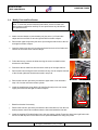
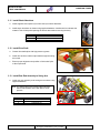
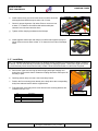
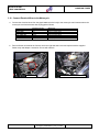
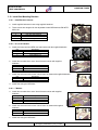
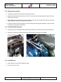
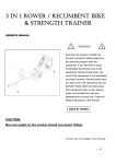
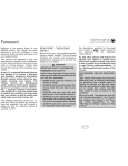
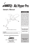
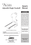
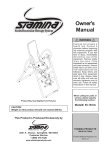
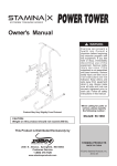
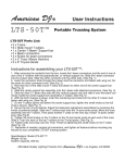
Trike Conversion Installation Manual
For
Honda VTX 1800 Motorcycles
ALL Models (Excluding C Model)
Revision 5
June 2010
Champion Motorcycle Accessories International Inc.
Dba Champion Sidecars
11841 Monarch Street, Garden Grove, CA 92841
(800) 875-0949 (714) 847-0949 Fax (714) 847-1539
www.championtrikes.com
Honda VTX 1800
TRIKE CONVERSION
CHAMPION TRIKES
Champion Trikes
Trike Conversion Kit for
Honda VTX 1800 Motorcycles
ALL Models Excluding C Model
Installation Manual
Page 2 of 19
Photography & Illustrations by Terry T. Emelio
Revision 4
Honda VTX 1800
TRIKE CONVERSION
CHAMPION TRIKES
Table of Contents
General Information ........................................................................................................................................... 4
1
1.1
Installation Information ................................................................................................................................ 4
1.2
For Your Safety ........................................................................................................................................... 4
1.3
Specifications............................................................................................................................................... 5
2
Removal of Original Parts ................................................................................................................................. 5
3
Installation of Champion Trike Conversion Kit ............................................................................................... 7
4
3.1
Modify Frame and Passenger Footrests. .................................................................................................... 7
3.2
Relocate Regulator ...................................................................................................................................... 7
3.3
Hose Stay .................................................................................................................................................... 7
3.4
Modify Front and Rear Brakes..................................................................................................................... 8
3.5
Install Swing Arm ......................................................................................................................................... 9
3.6
Install Rear Brake Line .............................................................................................................................. 10
3.7
Install Seat / Shock Mount to Frame ......................................................................................................... 10
3.8
Install Body Frame ..................................................................................................................................... 11
3.9
Install Body Frame Hanger Plates ............................................................................................................. 11
3.10
Install Support Struts ................................................................................................................................. 11
3.11
Install Shock Absorbers ............................................................................................................................. 12
3.12
Install Drive Shaft ...................................................................................................................................... 12
3.13
Install Rear End Assembly to Swing Arm .................................................................................................. 12
3.14
Connect Drive Shaft to Rear Differential ................................................................................................... 13
3.15
Modify OEM Mufflers ................................................................................................................................. 13
3.16
Install Header Pipes and Mufflers ............................................................................................................. 14
3.17
Install Body ................................................................................................................................................ 15
3.18
Connect Electrical Wires to the Motorcycle ............................................................................................... 16
3.19
Install Seat Mounting Brackets .................................................................................................................. 17
3.20
Align and secure body ............................................................................................................................... 18
3.21
Install Grab Rail (Optional) ........................................................................................................................ 18
3.22
Install Wheels ............................................................................................................................................ 18
Fastners ............................................................................................................................................................ 19
Installation Manual
Page 3 of 19
Photography & Illustrations by Terry T. Emelio
Revision 4
Honda VTX 1800
TRIKE CONVERSION
CHAMPION TRIKES
General Information
1
The Champion Sidecars Trike Conversion Kit is designed with the utmost consideration to safety, quality and
ease of installation. The kit comes complete with all necessary hardware and fasteners. However, it is assumed
that the installer has advanced and/or professional skills in motorcycle servicing. It is recommended that
installer obtain an OEM service manual for the vehicle to which the Trike Kit is to be installed.
1.1
Installation Information
The information contained in this Installation Manual is intended for use by technicians of advanced and/or
professional skill levels. Attempting installation without the proper training, tools and equipment could cause
injury to you or others. It could also damage the vehicle or cause an unsafe condition and can void the
warranty.
1.2
For Your Safety
Because this manual in intended for technicians of advanced to professional skill levels, we do not provide
warnings about many basic shop safety practices. If you have not received shop safety training or do not feel
confident about your knowledge of safety practices, we recommend that you do not attempt to perform the
procedures described in this manual.
Some of the most important general safety precautions are given below. Champion Sidecars cannot warn
you of every conceivable hazard that can arise. Only you can decide whether or not you should perform a
given task.
1.2.1
Important Safety Precautions
a. Make sure you have a clear understanding of all basic shop safety practices and that you wear appropriate
clothing and use safety equipment. Be especially careful of the following:
·
Read all directions before you begin, and make sure you have the tools, the parts and the skills required to
perform the tasks safely and completely.
·
Protect your eyes by using proper safety glasses, goggles or face shields any time you hammer, drill, grind,
pry or work around pressurized air or liquids, and springs or other stored-energy components.
·
Use other protective wear when necessary, for example gloves or safety shoes. Handling hot or sharp
parts can cause severe burns or cuts.
·
Protect yourself and others when you have a vehicle up in the air. Anytime you lift a vehicle, either by hoist
or a jack, make sure that it is securely supported.
b. Make sure the engine is turned off and the battery disconnected before you begin work.
·
Carbon Monoxide poisoning from exhaust gases: Be sure there is adequate ventilation whenever you run
the engine.
·
Burns from hot parts: Let the engine and exhaust system cool before working on those areas.
Installation Manual
Page 4 of 19
Photography & Illustrations by Terry T. Emelio
Revision 4
Honda VTX 1800
TRIKE CONVERSION
1.3
CHAMPION TRIKES
Specifications
Overall width
Overall length
Overall length w/ EZ-Steer
Wheelbase
Wheelbase w/ EZ-Steer
Load capacity
Brakes
Tires
Turning Radius
Wheels
Tire Pressure
55.5 in.
108.06 in.
111.75 in.
72.44 in.
76.125 in.
640 lbs.
High-performance rear disc
205/70R-15
12.3 ft.
Offset +35 mm 15x7JJ 4x4.5
20-25 psi
·
Suspension:
“Zero-Flex” swing arm and two new (replacement) Progressive coil-over shocks.
·
Rear Differential:
Champion Left Hand Drive Light Weight Rear Differential Assembly.
·
Brakes:
Original front plus 2 high performance disc brakes at rear.
·
Storage Capacity:
6.75 cubic feet – 3 full-face helmets and additional over wheel storage.
Removal of Original Parts
2
Secure and raise the motorcycle 9 to 10 inches using a quality motorcycle lift.
Remove the following from the vehicle. See OEM manual for detailed instructions. Items to be retained for reinstallation after modification are noted.
·
Rider’s Seat (to be re-installed without modification).
·
Passenger Seat and mounts (to be reinstalled without modification).
NOTE: OEM front and rear seat mounting bolts to be retained and reused.
·
Left and right passenger foot rests and mounts (to be reinstalled with modification).
·
Mufflers (to be re-installed and relocated with minor modification).
·
Rear Fender (complete w/ sub frame and all attaching parts).
·
Swing Arm, Drive Shaft and Rear Wheel (complete w/ brake line and all attaching parts).
Core Return
There are NO core return parts for this model.
Installation Manual
Page 5 of 19
Photography & Illustrations by Terry T. Emelio
Revision 4
Honda VTX 1800
TRIKE CONVERSION
CHAMPION TRIKES
3
Installation of Champion Trike Conversion Kit
3.1
Modify Frame and Passenger Footrests.
a. Use 17/64” drill and drill through frame from inside out using passenger footrest mount holes as guide.
b. Enlarge the passenger footrest mounting holes on the left and right side of the frame to 27/64”.
c.
Enlarge the holes in the left and right passenger footrest mounting plates to 27/64”.
d. Clean area of all debris.
3.2
Relocate Regulator
a. Install supplied “Z” bracket to the regulator as shown using the supplied
hardware.
Z-Bracket
b. Attach regulator to frame using the supplied hardware.
c.
Tie hoses down to avoid contact with the swing arm.
Qty
1
1
6
10
3.3
Description
¼-20x2 hex head bolt
¼-20x1-1/4 hex head bolt
¼-20 Nyloc nut
1/4- SAE flat washer
4 as spacers
Spacers (4)
Hose Stay
a. For models that have a recover tank below the swing-arm, a
holder has been included keep the hose connected to the water
pump away from the champion swing-arm.
b. Remove the hose from the top of the recovery tank.
c.
Push the water pump hose forward against transmission.
d. Secure hose with supplied stay as shown using existing bolt.
Ensure that hose is not being crushed. Bend stay if necessary.
e. Reconnect hose to recovery tank.
Installation Manual
Page 7 of 19
Photography & Illustrations by Terry T. Emelio
Revision 4
Honda VTX 1800
TRIKE CONVERSION
3.4
CHAMPION TRIKES
Modify Front and Rear Brakes
Note: To avoid the need to bleed the front brakes, ensure to follow front
brake system modification carefully. Do not open/remove any valves/lines
not specified below.
3
a. Attach vacuum bleeder to lower bleeder port (see arrow 1) of front brake
caliper and remove fluid. Do at both right and left front brake calipers.
b. Remove the upper banjo bolts (see arrow 2) securing the brake lines to the left
and right front brake calipers.
c.
1
Open the clamps (see arrow 3) securing the brake lines to the front fender and
remove the now loose lines from the clamps.
2
d. Follow the lines up; remove the bolts securing the cross over hard line and
blocks to the fork sliders.
e. Disconnect the two hard lines from the block at the top of the right side line.
f.
Remove the bolt securing the block mentioned in step 3.4e to complete removal
of the left and right brake lines disconnected in step 3.4b.
Disconnect hard lines
g. Remove the hard line, previously connected to upper block / line removed in
step 3.4f, from the rear brake master cylinder.
h. Install the supplied two plugs (M10-1.25 Allen Set Screws) to the now vacant
upper ports of the left and right front brake calipers.
Install plug
i.
Bleed front brakes if necessary.
j.
Remove the hard line, previously connected to the rear brake line, from the rear
brake pressure control valve located under the rider seat behind the fuel tank.
k.
Install the supplied 45” braided brake line to the rear master cylinder. Route line along lower right frame tube
and secure with Zip-ties. Ensure that line turns upward in front of the swing arm pivots.
Installation Manual
Page 8 of 19
Photography & Illustrations by Terry T. Emelio
Revision 4
Honda VTX 1800
TRIKE CONVERSION
3.5
CHAMPION TRIKES
Install Swing Arm
a. Install Champion swing arm. Ensure bearings and
bushings are present and properly positioned in swing
arm. Install with drive shaft tunnel to left hand side (LHS)
of the vehicle using the supplied pivot bolts (shouldered
bolt on the LHS).
b. Torque LHS (shouldered bolt) to 80 lb.ft. and RHS side
bolt to 25 lb.ft.
c.
Move swing arm up and down several times to seat
bearings. Retighten RHS pivot bolt to 25 lb ft
d. Install RHS OEM pivot lock nut. Hold pivot bolt while
tightening lock nut with Honda special tool (Honda PN 07ZMA-MCAA101), to 72 lb ft (108 N-m). Actual
torque is 80 lb.ft. However, with the special offset tool, the torque is 72 lb.ft.
e. Support swing arm to not allow it to hang on its own weight until shock absorbers can be installed.
Installation Manual
Page 9 of 19
Photography & Illustrations by Terry T. Emelio
Revision 4
Honda VTX 1800
TRIKE CONVERSION
3.6
CHAMPION TRIKES
Install Rear Brake Line
a. Install supplied residual valve to the previously installed braided brake line from
the rear master cylinder.
b. Install banjo end of 25” braided brake line to tee
fitting on rear differential as shown using supplied
hardware.
Qty
1
2
c.
Description
Banjo bolt
Crush washer
Route the brake line around to outboard side of the right shock
absorber and forward along the right leg of the swing arm. Secure to
swing arm leg with Zip-ties.
d. Connect the rear brake line to line from the rear master cylinder.
e. Secure the lines to the mounting bolt on the top, right side of the swing arm,
using an Adel clamp removed from the rear brake system and the supplied ¼”
flat washer and ¼” NyLoc nut.
f.
3.7
Bleed rear brakes.
Install Seat / Shock Mount to Frame
a. Install seat / shock mount to frame as shown using
supplied hardware.
Qty
2
2
4
8
4
Installation Manual
Description
14-1.5x65mm hex head bolt
M14 lock washer
3/8-24x3 ½” hex head bolt
3/8” flat washer
3/8” NyLoc nut
Page 10 of 19
Photography & Illustrations by Terry T. Emelio
Revision 4
Honda VTX 1800
TRIKE CONVERSION
3.8
CHAMPION TRIKES
Install Body Frame
a. Install body frame and modified passenger footrests to
frame as shown using supplied hardware.
b. Do not torque bolts at this time. Top bolts will be removed
later and foot pegs rotated to install body.
Qty
4
8
4
3.9
Description
10-1.25x55mm hex head bolt
10mm flat washer
10mm NyLoc nut
Install Body Frame Hanger Plates
a. Install left and right hanger plates as shown using supplied
hardware. Hanger plates fit inboard of body frame and shock
mount. Body fame to hang down on the bottom of the slots.
Torque to 45 lb.ft..
Qty
8
16
8
Description
3/8-24x1 1/4” hex head bolt
3/8” flat washer
3/8” NyLoc nut
3.10 Install Support Struts
a. Install left and right support struts as shown using supplied hardware. Struts fit inboard of body frame and
shock mount. Torque to 45 lb.ft.
Qty
8
16
8
Installation Manual
Description
3/8-24x1 1/4” hex head bolt
3/8” flat washer
3/8” NyLoc nut
Page 11 of 19
Photography & Illustrations by Terry T. Emelio
Revision 4
Honda VTX 1800
TRIKE CONVERSION
CHAMPION TRIKES
3.11 Install Shock Absorbers
a. Install supplied Heim spacers (four each shock) to shock absorbers.
b. Install shock absorbers as shown using supplied hardware. Install bolts from inboard side
outward. This will help with replacing the shocks later without removing the body.
Qty
4
8
4
Description
½-20x 2 ½” hex head bolt
½” flat washer
½-20 thin NyLoc nut
3.12 Install Drive Shaft
a. Grease driveshaft spline with high pressure grease.
b. Install drive shaft to vehicle output shaft through the swing
arm tunnel.
c.
Ensure proper alignment and position of drive shaft yoke
to the output shaft.
3.13 Install Rear End Assembly to Swing Arm
a. Install rear end assembly to the swing arm as shown using
supplied hardware.
Note: The lower bolts on the left and right sides have
the two flat washers on the bolt side to act as
spacers.
Qty
8
16
8
Installation Manual
Description
½-20x1 3/4” hex head bolt
½” flat washer
½-20 stover nut
Page 12 of 19
Photography & Illustrations by Terry T. Emelio
Revision 4
Honda VTX 1800
TRIKE CONVERSION
CHAMPION TRIKES
3.14 Connect Drive Shaft to Rear Differential
a. Secure the drive shaft to the rear differential using the
hardware shipped on the input flange of the differential.
3.15 Modify OEM Mufflers
3.15.1 R S and T models
a. Remove OEM chrome tips and heat / beauty covers from mufflers. Cut
welds and/or unscrew bolts as required. Be careful not to cut into the
muffler. (If you do – weld it closed).
b. Clean cut areas for installation of supplied tips later.
c.
Cut off discharge tips as shown.
Enlarge slot
d. Enlarge muffler tab rear slot to accommodate a 3/8” bolt.
3.15.2 F and N Models
a. Remove OEM chrome heat / beauty covers from mufflers. Cut welds and/or unscrew bolts as required. Be
careful not to cut into the muffler. (If you do – weld it close).
b. Either the OEM or the supplied muffler tips may be used. If it is desired to use the supplied tips, OEM tips
must be removed.
c.
Enlarge muffler tab rear hole to accommodate a 3/8” bolt.
Installation Manual
Page 13 of 19
Photography & Illustrations by Terry T. Emelio
Revision 4
Honda VTX 1800
TRIKE CONVERSION
CHAMPION TRIKES
3.16 Install Header Pipes and Mufflers
a. Install upper, rear muffler bracket to rear tabs of body frame as
shown using supplied hardware. Do not over tighten bolts to
over compress rubber vibration rubbers (only two threads
exposed).
b. Install muffler extensions to header pipes: Top header pipe
(rear cylinder) with short supplied extension to Right Side
Muffler position and Bottom header pipe (front cylinder) with
long supplied extension to Left Side Muffler position using
supplied clamps and gaskets.
Clamp & gasket
c.
Fit mufflers to exhausts extensions. Ensure the mufflers are oriented as
shown.
d. Install bottom exhaust
clamps as shown.
(Mufflers not illustrated for
clarity). Ensure rear
carriage bolt is installed
from top downward (body
will not fit if reversed).
Front carriage bolt is
installed from bottom
upward. DO NOT tighten
clamping hardware at this
time. Hardware to be
tightened after cross-over
tubes are installed.
Installation Manual
Page 14 of 19
Photography & Illustrations by Terry T. Emelio
Revision 4
Honda VTX 1800
TRIKE CONVERSION
CHAMPION TRIKES
e. Install exhaust cross over and J-tube tubes to mufflers as shown
with supplied and OEM clamps at either end of J-tube.
f.
Exhaust extension tubes not illustrated
Check for proper alignment of all tubes. Ensure cross over has
at least ½” of clearance from differential and has adequate
clearance over exhaust extension tubes.
g. Tighten muffler clamping hardware and all clamps.
Supplied Clamps
OEM Clamp
h. Install supplied exhaust tips and clamps to mufflers with supplied clamps as
shown. Ensure screens have at least ½” of clearance from ends of discharge
tubes.
3.17 Install Body
Note: The installation/alignment of the body is an iterative process to find the correct position of body in relation to
the wheels. The four holes already in the body are primarily for shipping purposes. These holes might line up with
the pre-drilled body frame holes when the body is fitted. Follow instructions below to re-drill holes if required.
a. Remove the upper bolt securing the left and right passenger footpegs and
body frame to the vehicle frame. Rotate the footpegs forward to allow space for
the body to pass.
b. Carefully position body over seat / shock and body frames.
c.
Position the four mounting holes already in the body above the corresponding
body frame tabs and test fit with the supplied bolts.
d. Final alignment of the body will be done after the seat mounting brackets are
installed in section 3.18
Qty
6
6
6
6
Installation Manual
Description
3/8-24x1-1/4 hex head bolt
3/8x1-1/2 fender washer
3/8 SAE flat washer
3/8-24 Nyloc Nut
Page 15 of 19
Photography & Illustrations by Terry T. Emelio
Remove bolt & pivot
footrest forward
Revision 4
Honda VTX 1800
TRIKE CONVERSION
CHAMPION TRIKES
3.18 Connect Electrical Wires to the Motorcycle
a. Connect the electrical wires from the pigtail attached to the body to the motorcycle main harness where the
motorcycle rear fender harness was unplugged as follows:
Running lights
Brake lights
Turn signal, right
Turn signal, left
Accessory
Ground
Champion harness
Blue & Brown
Red
Green
Yellow
Blue
Black (two)
Motorcycle
Black w/ Brown stripe
Green w/ Yellow stripe
Blue
Orange w/ White stripe
with Running Lights
Green (two)
b. Remove flasher unit behind the fuse box under the right side side-cover and replace with the supplied
flasher relay and adapter / extension. Secure with cable tie.
OEM flasher unit
Installation Manual
Champion flasher and adapter installed
Page 16 of 19
Photography & Illustrations by Terry T. Emelio
Revision 4
Honda VTX 1800
TRIKE CONVERSION
CHAMPION TRIKES
3.19 Install Seat Mounting Brackets
3.19.1 Install Backrest mounts
a. Install supplied backrest mounts using supplied hardware.
b. These mounts are designed for the adjustable Honda OEM backrest PN 08F75MCH-130
Qty
4
8
4
Description
5/16-18x1 hex head bolt
5/16 SAE flat washer
5/16-18 Nyloc nut
3.19.2 R, S, N & T Models:
a. Install previously removed OEM rear seat bracket with the supplied hardware
Qty
2
4
2
Description
5/16-18x1 hex head bolt
5/16 SAE flat washer
5/16-18 Nyloc nut
b. Install rider seat bracket to seat / shock frame as shown with supplied
hardware.
Qty
2
4
2
c.
Description
5/16-18x1 hex head bolt
5/16 SAE flat washer
5/16-18 Nyloc nut
Install rear seat mount tab to seat / shock frame as shown with supplied hardware.
Qty
2
2
Description
5/16-18x1 hex head bolt
5/16 SAE flat washer
d. Install Seat using the OEM bolts
3.19.3 F Models:
a. Install rider seat bracket to seat / shock frame as shown with supplied
hardware.
Qty
2
4
2
Description
5/16-18x1 hex head bolt
5/16 SAE flat washer
5/16-18 Nyloc nut
b. Install rear seat mount tab to seat / shock frame as shown with supplied
hardware.
Qty
2
2
c.
Description
5/16-18x1 hex head bolt
5/16 SAE flat washer
Install Seat using the OEM bolts.
Installation Manual
Page 17 of 19
Photography & Illustrations by Terry T. Emelio
Revision 4
Honda VTX 1800
TRIKE CONVERSION
CHAMPION TRIKES
3.20 Align and secure body
a. Temporarily install wheels to help with the alignment process.
b. Align body with the wheels and the shock tower mount. Remove previously installed four bolts if the body
needs more movement.
c.
When aligned, drill from below through frame tabs two center tab holes through body and bolt it down with
supplied hardware. Body will now be locked in position.
d. If required, drill from below the original four holes and bolt down with supplied hardware. It may be easier if
the wheels are removed for this process
3.21 Install Grab Rail (Optional)
a. Locate grab rail on mounting bracket and temporarily position the seat. Move grab rail to desired position.
b. Use tape on the body to mark grab rail position. Drill two holes accordingly and assemble.
3.22 Install Wheels
a. Install wheels to rear end using supplied lug nuts.
b. Torque lug nuts to 75 lb.ft.
Installation Manual
Page 18 of 19
Photography & Illustrations by Terry T. Emelio
Revision 4
Honda VTX 1800
TRIKE CONVERSION
CHAMPION TRIKES
Fastners
4
VTX Hardware Kit
PART NUMBER: HWK-L00-100
Qty
Part #
16
32
16
HW-375-052
HW-375-016
HW-375-011
A. HANGER BRACKETS/STRUTS
Description
REV 1
3/8-24x1-1/4 hhcs gr8 yellow zinc
3/8 SAE flat washer clear zinc
3/8-24 nylock nut clear zinc
B. SWING ARM TO REAR END
8
8
20
HW-500-027
HW-500-008
HW-500-020
1/2-20x1-3/4 hhcs gr8 yellow zinc
1/2-20 stover nut
1/2 SAE flat washer clear zinc
C. SHOCK TOWER
2
2
4
8
4
10
8
18
HW-M14-004
HW-M14-005
HW-375-083
HW-375-016
HW-375-011
HW-312-005
HW-312-009
HW-312-017
M14x1.5x65 hhcs clear zinc
M14 Lock Washer
3/8-24x3-1/2 hhcs gr8 yellow zinc
3/8 SAE flat washer clear zinc
3/8-24 nylock nut clear zinc
5/16-18x1 hhcs gr8 yellow zinc
5/16-18 nylock nut clear zinc
5/16 SAE flat washer clear zinc
HW-500-006
HW-500-020
HW-500-034
1/2-20x2-1/4 hhcs gr8 yellow zinc
1/2 SAE flat washer clear zinc
1/2-20 nylock nut THIN ss
D. SHOCKS
4
8
4
1300 1800
E. FRAME to MOTORCYCLE
M10x1.25x55 hhcs gr8.8 (1800 only)
4
M10x1.25 nylock nut clear zinc (1800 only)
4
M10 flat washer clear zinc (1800 only)
8
1/2-20x1-1/4 hhcs gr8 yellow zinc
2
1/2 lock washer clear zinc (1300 Only)
2
1300 1800
F. REGULATOR MODULE / CANISTER
4
4
8
2
2
HW-M10-031
HW-M10-022
HW-M10-005
HW-500-037
HW-500-021
4
10
1
2
4
2
4
HW-250-005
HW-250-004
HW-250-020
HW-375-054
HW-375-016
HW-375-011
HW-250-022
1/4-20 nylock nut clear zinc
1/4 SAE flat washer clear zinc
1/4-20x2 hhcs gr8 yellow zinc
3/8-24x1-3/4 hhcs gr8 yellow zinc
3/8 SAE flat washer clear zinc
3/8-24 nylock nut clear zinc
1/4-20x1-1/4 hhcs gr8 yellow zinc
4
8
2
4
2
4
2
1
G. BODY TO FRAME
6
6
6
6
HW-375-011
HW-375-052
HW-375-007
HW-375-016
3/8-24 nylock nut clear zinc
3/8-24x1-1/4 hhcs gr8 yellow zinc
3/8x1-1/2 fender washer clear zinc
3/8 SAE flat washer clear zinc
H. MUFFLER HANGERS
1
1
2
2
--HW-375-016
HW-375-012
Installation Manual
3/8-16x6-1/2 carraige bolt, SQ neck, zpl
3/8-16x5-1/2 carraige bolt, SQ neck, zpl
3/8 sae flat washer clear zinc
3/8-16 nylock nut clear zinc
Page 19 of 19
Photography & Illustrations by Terry T. Emelio
Revision 4