1
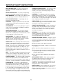
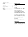
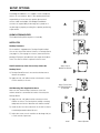
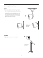
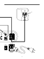
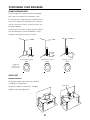
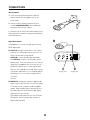
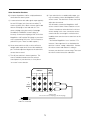
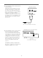
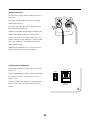
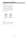
POWERED SATELLITE/SUBWOOFER SYSTEM
USER MANUAL
The lightning flash with arrowhead,
within an equilateral triangle, is intended
to alert the user to the presence of
uninsulated “dangerous voltage” within
the product’s enclosure that may be of
sufficient magnitude to constitute risk
of electric shock to persons.
The exclamation point within an equilateral triangle is intended to alert the user
to the presence of important operating
and maintenance (servicing) instructions
in the literature accompanying this
product
WARNING
AVISIQUE
POUR EVITER TOUT RISQUE DE
CHOC ELECTRIQUE, NE PAS
DEMONTER LE COUVERCLE DU
HAUT PARLEUR. AUCUN ENTRETIEN DES PIECES INTERIEURES
N’EST REQUIS.TOUT SERVICE
D’ENTRETIEN NE DOIT ETRE
EFFECTUE QUE PAR DU PERSONNEL D’ENTRETIEN QUALIFIE.
DO NOT OPEN
TO PREVENT THE RISK OF ELECTRIC
SHOCK, DO NOT REMOVE
SPEAKER’S COVER. NO USERSERVICEABLE PARTS INSIDE.
REFER SERVICING TO QUALIFIED
SERVICE PERSONNEL.
READ AND HEED IMPORTANT SAFETY WARNING
ON SIDE OF SPEAKER ENCLOSURE
CAUTION:
IMPORTANT NOTICE:
TO PREVENT ELECTRIC SHOCK, MATCH WIDE
BLADE OF PLUG TO WIDE SLOT, INSERT FULLY.
THE SERIAL NUMBER FOR THE SPEAKER IS
LOCATED ON THE SPEAKER’S CONTROL PANEL.
PLEASE WRITE THIS NUMBER DOWN AND KEEP IT
IN A SECURE AREA. THIS IS FOR YOUR SECURITY.
ATTENTION:
POUR EVITER LES CHOCS ELECTRIQUES, INTRODUIRE LA LAME LA PLUS LARGE DE LA FICHE
DANS LA BORNE CORRESPONDANTE DE LA PRISE
ET POUSSER JUSQU’AU FOND.
2
IMPORTANT SAFETY INSTRUCTIONS
READ INSTRUCTIONS – All safety and operating
instructions should be read before the speaker is
operated.
POWER-CORD PROTECTION – The AC power cords
should be routed so that they are not likely to be
walked on. No object should bring weight to bear on
to the AC power cords.
RETAIN INSTRUCTIONS – The safety and operating
instructions should be retained for future reference.
LIGHTNING – For added protection for the speaker
during a lightning storm, or when it is left unattended
and unused for long periods of time, unplug them from
the wall outlet. This will prevent damage to the speaker
due to lightning and power-line surges.
HEED WARNINGS – All warnings on the speaker and
in the operating instructions should be adhered to.
FOLLOW INSTRUCTIONS – All operating and use
instructions should be followed.
OVERLOADING – Do not overload wall outlets, extension cords, or integral convenience receptacles as this
can result in a risk of fire or electric shock.
CLEANING – Unplug the speaker from the wall outlet
or other power source before cleaning. Use a damp
cloth for cleaning.
OBJECT AND LIQUID ENTRY – Never use probes of
any kind to reach into the speaker as they may touch
dangerous voltage points or short parts that could
result in a fire or electric shock. Never spill liquid of
any kind on the speaker.
ATTACHMENTS – Do not use any adapters or attachments not recommended by Cambridge SoundWorks
as they may cause hazards.
WATER AND MOISTURE – Do not use the speaker
near water-for example, near a bath tub, wash bowl,
kitchen sink, or laundry tub; in a wet basement; or near
a swimming pool or other similar areas.
SERVICING – Do not attempt to service the speaker
yourself as opening or removing covers may expose
you to dangerous voltage or other hazards. Refer all
servicing to qualified service personnel.
ACCESSORIES – Do not place the speaker on an
unstable cart, stand, tripod, bracket, or table. The
speaker may fall, causing serious injury to a child or
adult and serious damage to the product.
DAMAGE REQUIRING SERVICE – Unplug the speaker from the wall outlet or other power source and refer
servicing to qualified service personnel under the following conditions:
VENTILATION – Slots, openings and metal fins in the
cabinet are provided for ventilation, to ensure reliable
operation of the speaker and to prevent it from overheating. These areas must not be blocked or covered
such as by placing the product on a bed, sofa, very
deep pile rug, or other similar surface. The speaker
should not be placed in a built-in installation such as a
bookcase or rack.
a) When the power-cord or plug is damaged.
b) If liquid has been spilled, or objects have fallen into
the speaker.
c) If the speaker has been exposed to rain or water.
d) If the speaker does not operate normally by following the operating instructions; or exhibits a distinct
change in performance.
HEAT – The speaker should be situated away from heat
sources such as radiators, heat registers, stoves, and
other products (including amplifiers) that produce heat.
e) If the speaker has been dropped or damaged in
any way.
POWER SOURCES – The speaker should be operated
only from the type of power source indicated on the
label. If you are not sure of the type of power supply to
your home, consult your dealer or local power company.
REPLACEMENT PARTS – When replacement parts
are required, be sure the service technician uses
replacement parts specified by Cambridge
SoundWorks or have the same characteristics as the
original part. Substandard substitutions may result in
fire, electric shock, or other hazards.
POLARIZATION – The speaker is equipped with a
polarized alternating-current line plug (a plug having
one blade wider than the other). This plug will fit into
the power outlet only one way. This is a safety feature.
If you are unable to insert the plug fully into the outlet,
try reversing the plug. If the plug should still fail to fit,
contact your electrician to replace your obsolete outlet.
Do not defeat the safety purpose of the polarized plug.
SAFETY CHECK - Upon completion of any service or
repairs to the speaker, ask the service technician to
perform safety checks to determine that the speaker is
in proper operating condition.
3
TABLE OF CONTENTS
Introduction ................................................................4
INTRODUCTION
Carton Contents..........................................................5
Thanks for choosing the MegaWorks 210D
Setup Options..........................................................6-7
loudspeaker.
Wiring Diagram........................................................8-9
It features the finest drivers, precision internal
Positioning Your Speakers ..................................10-11
crossover and amplifier circuitry and an elegant enclo-
Connections ........................................................12-13
sure design.
Final Adjustment ......................................................14
Cleaning ..................................................................14
The satellite speakers feature “rare earth” magnetic
Specifications ..........................................................15
assemblies which are strong, yet small and light. This
Fuse Replacement....................................................15
increases the interior volume of the satellite enclosure
for better low frequency performance.
The Product Development Team at Cambridge
SoundWorks believes there is no better combination of
audiophile-level attention to detail and reasonable cost.
Inspecting For Damage
Examine the speaker system carefully for shipping
damage. If there is any, do not install or use the system. Return the speaker to the store where you made
the purchase or call Cambridge SoundWorks at 1-800
FOR-HIFI (1-800-367-4434) for assistance.
After Unpacking
Store the shipping carton and packing material for
future transport needs.
QUICK SETUP
If you have connected amplified subwoofer/satellite
systems before, the Wiring Guide on pages 8-9 may
be all you need to get set up and operating.
4
CARTON CONTENTS
A) Two Satellite Loudspeakers
B) Desktop Stands,Thumb screws (installed on satellites)
B
A
C) Wallmount hardware, Self-adhesive Feet
D) Hook and Loop fastener (for volume control, if not
used on Desktop Stand)
E) One Subwoofer/Amplifier Loudspeaker
F) AC Cord
G) Volume Control
H) 2 Satellite Connection Cables (2-meters)
Both signal cables (listed below) are
C
2-meters long.
No.10 screws and
plastic wall anchors
I) Single-Channel Signal Cable, Black RCA Phono Plug
to Yellow/Orange 3.5 mm Miniplug
Plugs into DIGITAL IN
D
Connect to a minijack digital output, like the
E
one found on Creative Sound Blaster Live! 5.1
sound cards.
J) Stereo Signal Cable, Green Miniplug
to Green Miniplug
Plugs into analog LINE IN A or LINE IN B
Connect to any analog sound source with a 3.5 mm
stereo output jack, like Cambridge SoundWorks
MusicWorks™, a portable CD player, a small headphone
jack, or a computer sound card.
F
G
H
To Signal Source
I
J
5
Signal Cables
To MegaWorks
SETUP OPTIONS
Cambridge SoundWorks, Inc. supplies screws and plastic
anchors for convenience, but it is the speaker purchaser’s
responsibility to insure that any speaker placement is
secure, stable and reliable. Cambridge SoundWorks
assumes no responsibility for damage to its products or
any damage to property resulting from speaker positioning
A
or placement.
SUBWOOFER/AMPLIFIER
The Subwoofer/Amplifier requires no assembly.
SATELLITES
Desktop Placement
Each satellite is shipped with a Desktop Stand installed.
You can also install the Volume Control to a Desktop Stand
(see page 12). Some program sources (stereo televisions,
portable CD players) provide their own output level adjustment. The volume control is optional in these cases.
B
Shelf Placement (or other flat surface) without the
Apply Feet to
Bottom for Shelves
Desktop Stand
A) Desktop Stand Removal: unscrew the thumbscrew to
release the satellite.
B) Apply the soft, self-adhesive feet to the bottom surface
of each satellite, as shown.
C
Apply Feet to Back
for Wall Mounting on
Screwhead
Wall Mounting With Supplied Hardware
Note: Use the “hook and loop” fastener to secure the
volume control to a convenient flat surface if not using the
Desktop Stand
D
C) Apply the soft, self-adhesive feet to the back of the
E
satellite as shown. The feet improve stability mounting
and protect the finish of both the wall and the satellite.
D) Install the No.10 screw and anchor in the wall so that its
screwhead protrudes about 3/8 inch.
E) Adjust the screw so each satellite can be hung with just
a small amount of pressure.
Install
6
Mount Speaker
Wall Mounting With A Swivel Bracket
Contact Cambridge SoundWorks about available swivel
brackets.
F) Follow the installation instructions for your particular mounting bracket to attach it to a flat surface.
You can install the whole bracket/satellite assembly
inverted. This places the bracket above the satellite, concealing it when viewed from below. In this
case, remove, invert and re-install the the satellite
F
grille to position the logo correctly.
Remove, Invert
and Replace
Grille Panel
Floor Stands
G
G) Follow the instuctions included with the Newton
ST300 Floor Stands to install the satellites.
Using Speakers
on a Stand
7
CONNECTION DIAGRAM
RED
DIGITAL OUT
I
Yellow/Orange plug – to a minijack digital output
(for instance, a Sound Blaster Live! 5.1 sound card)
Digital Signal Cable
PO
TREBLE
BASS
+
Analog Signal Cable
J
8
Green plug – to a stereo minijack analog output
(MusicWorks, sound card, portable CD player)
+
RED
OWER/STANDBY
DIGITAL IN
SPEAKERS
+
L
LINE IN
A
R
B
+
VOLUME CONTROL
120VAC 60Hz
POWER
RISK OF FIRE
REPLACE FUSE
AS MARKED
9
POSITIONING YOUR SPEAKERS
SUBWOOFER/AMPLIFIER
Place the Subwoofer cabinet on the floor, preferably
near a wall. Do not place it on a desktop or shelf.
For maximum bass output, place the subwoofer near a
corner. If the subwoofer is placed away from the intersection of two room surfaces, the maximum bass output will be reduced.
Use the Bass Level control to adjust the bass output to
your desired balance. Recommended Bass control
settings for each type of location are shown.
Maximum Bass Output
Moderate Bass Output
Least Bass Output
BASS
BASS
BASS
Suggested
Bass Control
Compensation
+
+
+
SATELLITES
Desktop Placement
The Desktop Stands improve the sound for both
a standing or seated listener.
MusicWorks
Position the satellites so they form a 45 degree
angle from your listening position.
45 ˚
10
le
ang
le
ang
45 ˚
POSITIONING THE SATELLITES
Wall Placement
Avoid facing a satellite parallel to a nearby wall (within
6-8 inches). The reflected sound from the wall
A
degrades the sound coming directly from the satellite
(diagram A).
Try to position wall-mounted satellites so both are
approximately at your ear level while sitting or slightly
OK
higher. Make sure the speakers form at least a 20degree angle with your listening position. An angle
greater than 55 degrees sounds like two separate
speakers, rather than forming a continuous image of
sound between the two speakers (diagram B).
Too
Close
When using the speaker for video sound, place the
Too
Close
satellites relatively close to the television monitor, forming no more than a 45 degree angle with your listening
position (diagram C).
B
MAXIMUM RECOMMENDED DISTANCE
APART FOR HOME THEATER
RECOMMENDED DISTANCE
APART FOR STEREO
20 - 55
ANGLE
C
EAR LEVEL
OR
SLIGHTLY
HIGHER
LEVEL
WITH
CENTER
SPEAKER
45 ANGLE
POWERED
SUBWOOFER
Shelf Placement
Place the satellites as close to the edge of the shelf as
D
possible for best sound (diagram D).
Flush with edge if possible
11
CONNECTIONS
Volume Control
A) If you are using the Desktop Stand, slide the
Volume Control onto the support strut on one
of the stands.
A
B) Insert the Volume Control’s plug into the jack
marked VOLUME CONTROL on the Subwoofer
input panel until it snaps in place.
It is not necessary to connect the Volume Control if your
audio signal source provides an output level adjustment
you would rather use.
B
Signal Connections
The MegaWorks 2.1 has two analog inputs and one
SPDIF digital input.
C) LINE IN A (analog): Connect the 3.5 mm minijack
output of any analog signal source to this 3.5 mm
POWER/STANDBY
DIGITAL IN
SPEAKERS
+
TREBLE
BASS
L
stereo minijack input, using cable J.
LINE IN
A
LINE IN B is a second audio input that blends
+
+
R
B
with LINE IN A. Connect a second audio source
+
VOLUME CONTROL
program here. For a source with a 3.5 mm minijack
output (like a headphone jack or line out jack on a
portable CD player), use a 2-meter signal cable
with a 3.5 mm miniplug at each end. Other sources
C
D
may need a cable with a 3.5 mm miniplug and two
Analog Inputs
Digital Input
RCA plugs or a 3.5 mm stereo miniplug and 3.5
mm stereo
minijack.
D) DIGITAL IN: Connect the output of a digital audio
signal source to this RCA jack. You can use cable I
to connect to most computer sound card digital
outputs. When a digital signal is present, the analog audio inputs are automatically muted. Digital
signal format is auto-sensed.
Typical digital audio signals are 44.1 kHz 16 bit (like
CD audio) or 48 kHz 16 bit (like that stored on a
Digital Audio Tape-DAT).
12
Other Connection Situations
d) If your television has a variable audio output, you
1) Using the MegaWorks 210D as a high performance
may not need to connect the MegaWorks 210D’s
stereo television sound system.
volume control. The television’s remote control will
a) A stereo television with audio signal output typically
adjust the volume level.
has two RCA-type jacks (one red, one white). To
You will need to connect the MegaWorks 210D
connect to these jacks, obtain a stereo signal cable
volume control if either of these situations occurs:
with two RCA plugs at one end and a 3.5 mm
* Noise is heard even at the television’s minimum
stereo miniplug at the other end (a Cambridge
volume setting. In this case, connect the volume
SoundWorks A12MMSRC 2-meter cable, for
control and set it low enough to make the noise
instance). Connect the miniplug to LINE IN A of the
inaudible, then stow the volume control next to the
MegaWorks 210D and the RCA plugs to your televi-
subwoofer.
sion’s red and white RCA jacks. (Do not connect to
* You find the MegaWorks is too “sensitive.” For
yellow RCA jacks. These are video outputs.)
instance, if the output level is too loud when the
b) Some stereo televisions offer a choice of fixed or
television “volume” setting is below 30%. Connect
variable audio output level. Choose the variable out-
the volume control and reduce it’s setting to
put. The fixed output level bypasses the television’s
increase your television’s volume range. Then stow
remote volume control.
the volume control next to the subwoofer.
c) Turn off your television’s internal speakers. This
control could be located on the front or back
control panels of your television, or it may be an
“on-screen” menu selection.
VIDEO IN
1
2
AUDIO
OUT
3
(VARIABLE)
VIDEO
L
(MONO)
AUDIO
R
Signal Cable
One 3.5 mm stereo miniplug to two RCA plugs
To MegaWorks 210D
LINE IN A or LINE IN B
13
2) Using the MegaWorks 210D as a sound system for a
component CD player.
COMPONENT CD OUTPUT
Typically, there are two RCA-type jacks (one red,
one white) on the CD player. To connect to these
OUTPUTS
jacks, obtain a stereo signal cable with two RCA
plugs on one end and a 3.5 mm stereo miniplug at
RIGHT LEFT
the other end (a Cambridge SoundWorks
A12MMSRC 2-meter cable, for instance). Connect
the miniplug to LINE IN A of the MegaWorks 210D
and the RCA plugs to your CD player’s red and
white RCA jacks.
Signal Cable
One 3.5 mm stereo miniplug to two RCA plugs
COMPONENT WITH RCA JACK DIGITAL OUTPUT
3) Using the MegaWorks 210D as a sound system for a
home stereo component with a digital output.
OUTPUTS
A home component digital output will typically be
an RCA-type jack. To connect to this output, obtain
RIGHT LEFT
a signal cable with an RCA plug at each end (a
DIGITAL OUTPUTS
COAX
OPTICAL
Cambridge Works A1DCOAX2 2 meter cable, for
instance). If a cable with one RCA plug at each
end can’t be obtained, a stereo version can be
Signal Cable
One RCA plug to one RCA plugs
used. Just use one plug at each end of the
same color.
The MegaWorks 210D does not support optical
digital signals. The digital RCA jack output of many
components is labeled “coax” or “coaxial.”
14
Speaker Connections
To connect the 2-meter speaker cables (two wires at
each end):
Push back the red speaker input tab on a satellite,
exposing the wire hole.
Fully insert one of the wires with a red band into the
wire hole and release the tab.
Repeat the procedure with the adjacent speaker wire
and the black speaker input tab on that speaker.
Connect the two wires at the other end of that same
speaker cable to the red and black “R” speaker input
tabs on the subwoofer. This satellite becomes the
Right channel satellite.
Repeat the preceding process to connect the other
satellite (making it the Left channel satellite).
AC Connection and Placement
Make sure the subwoofer Power switch is in the OFF
120VAC 60Hz
position (O).
POWER
Plug the supplied power cable first into the subwoofer
back panel AC socket. Then connect it to an AC
power socket.
Place the satellites and subwoofer in their preferred
RISK OF FIRE
REPLACE FUSE
AS MARKED
positions, then switch the Power swith to the ON (I)
position.
15
OPERATION AND FINAL ADJUSTMENT
1) Use the Volume Control or the signal source control
to vary output level.
2) Defeat or cancel any “tone control” or other sound
adjustments within your audio program source.
Portable CD players may have “bass boost” switches and many computer sound programs have
audio adjustments concealed in drop-down menus.
3) If possible, play a variety of musical CDs with good
deep bass content to judge the best setting of the
Bass and Treble controls.
TREBLE
BASS
+
+
Cleaning
The painted surfaces of the satellites and subwoofers
should be wiped with a damp cloth or brushed clean.
The grille panel material can be vacuumed or brushed
clean.
16
SPECIFICATIONS
FUSE REPLACEMENT
Analog Input:
IMPORTANT: Turn off and unplug the
speaker before changing the fuse.
775 millivolts for full output
10 kohms input impedance
Digital Input:
Supports 32 kHz, 44 kHz, 48 kHz and 96 kHz data
rates, any word length up to 24 bits.
Amplifiers:
Satellite: 60 watts continuous at 1 kHz, two channels
driven at less than .1% total harmonic distortion.
Subwoofer: 150 watts continuous at 100 Hz, one channel driven at less than .3% total harmonic distortion.
System Frequency response:
Satellite: 150 Hz to 15 kHz, +/- 3 dB
Subwoofer: 32 Hz to 150 Hz +/- 3 dB
Use only with a 250V fuse
Employer uniquement avec
un fusible de 250V
2.
3.
4.
5.
Drivers:
Nominal 8 inch subwoofer driver
Nominal 3.5 inch satellite driver
AC Voltage:
120VAC, 60Hz
Dimensions (H x W x D) and Weights
Satellite (without stand)
4 1/2" x 4 3/8" x 4 7/8"
113mm x 108mm x 125mm
1 pound, 1ounce
482 grams
Fuse Replacement
Satellite (with stand)
The fuse holder is located in the power connector
at the base of each speaker. The fuse is a 2.5A
MDL type.
6 1/4" x 4 3/8" x 5 5/8"
160mm x 108mm x 143mm
1 pound, 3 ounces
To replace the fuse:
1. Unplug the AC cord from the AC power source,
then remove the AC power cord from the speaker’s
power connector.
2. Remove the fuse cap with a small, flat blade screwdriver (see diagram 2).
3. Remove the fuse from the fuse cap
(see diagram 3).
4. Replace the fuse inside fuse cap with another metric 5X20mm size fuse (see diagram 4).
5. Replace the fuse and cap in the power connector
(see diagram 5).
6. Connect the AC power cord to the speaker.
7. Connect the power cord to an AC power outlet.
539 grams
Subwoofer
11 1/8" x 10" x 10"
263mm x 255mm x 255mm
14 pounds, 8 ounces
6.6 kg
17
CAMBRIDGE SOUNDWORKS, INC.
311 Needham Street, Newton MA, 02464
Telephone: 1-800-367-4434
Fax: 1-617-527-3194
A
Company
P81-1750