1
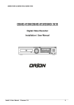
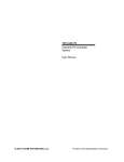
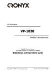
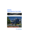
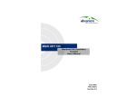
VRD 3004/8 Digital Surveillance System User’s Manual CDV-L2.1 VRD 3004/8 user manual Contents 1 INTRODUCTION .......................................................................................................................6 1.1 FUNCTION INTRODUCTION ................................................................................................6 1.2 SOFTWARE FEATURES .......................................................................................................8 1.3 HARDWARE FEATURE .........................................................................................................8 2.0 INSTALLATION SETTING.........................................................................................................9 2.1 FRONT PANEL VIEW ..................................................................................................................9 2.2 REAR PANEL VIEW ...............................................................................................................9 2.3 LED INDICATORS ............................................................................................................... 10 2.4 EXTERNAL CONNECTOR .......................................................................................................... 10 2.5 VRD 3004 REMOTE COTROLLER................................................................................ ......15 3. INSTALLATION SETTING......................................................................................................... 17 3.1 CABLE CONNECTION......................................................................................................... 17 3.2 POWER CONNECTOR........................................................................................................ 20 3.3 LOCK AND UNLOCK OF FRONT PANEL BUTTONS: ........................................................................ 20 3.4 WARNING ............................................................................................................................ 20 4.VRD 3004 SYSTEM OPERATION: ..................................................................................... .......22 4.1 SPLIT DISPLAY.................................................................................................................... 22 4.3 CONTROL PANEL FUNCTION BUTTON INTRODUCTION: ............................................... 25 4.3.3 FUNCTION OF CONTROL PANEL BUTTONS.............................................................. 25 5 MAIN MENU FUNCTION............................................................................................................ 27 5.1 RECORDING SETTING ....................................................................................................... 28 5.1.1 CAMERA SELECT......................................................................................................... 28 5.1.2 Microphone Select ......................................................................................................... 28 5.1.3 SCHEDULE RECORD................................................................................................... 28 5.1.3.2 ITEM SELECT ...................................................................................................... 29 5.1.3.3 WEEK DAY ........................................................................................................... 29 5.1.3.4 START ..................................................................................................................29 5.1.3.5 WEEKDAY ............................................................................................................ 29 5.1.3.6 STOP.................................................................................................................... 29 5.1.3.7 ADD SCHEDULE.................................................................................................. 29 Page 2 of 54 VRD 3004/8 user manual 5.1.3.8 REMOVE SCHEDULE.......................................................................................... 29 5.1.3.9 MODIFY SCHEDULE ........................................................................................... 29 5.1.3.10 RESTORE SCHEDULE...................................................................................... 29 5.1.3.11 SAVE SCHEDULE .............................................................................................. 29 5.1.3.12 APPLY TO ALL.................................................................................................... 29 5.1.4 CONTINUE RECORD.................................................................................................... 30 5.1.5 EVENT RECORD .......................................................................................................... 30 5.1.5.1 MOTION RECORD............................................................................................... 30 5.1.5.1.1 MOTION SENSITIVITY:..................................................................................... 30 5.1.5.1.2 MOTION SET AREA:......................................................................................... 31 5.1.5.1.3 MOTION RESET AREA ..................................................................................... 31 5.1.5.1.4HIDDEN FRAME ................................................................................................ 31 5.1.5.2 ALARM RECORD ................................................................................................. 31 5.1.5.2.1 ALARM IN ......................................................................................................... 32 5.1.5.2 .2 TRIGGER REC DURATION............................................................................. 32 5.1.6 RECYCLE RECORD ..................................................................................................... 32 5.1.7 APPLY TO ALL............................................................................................................... 32 5.2 CAMERA SETTING.............................................................................................................. 32 5.2.1 CAMERA SELECT......................................................................................................... 32 5.2.2 CAMERA NAME ............................................................................................................ 33 5.2.3 HIDDEN CAMERA......................................................................................................... 33 5.2.4 RECORDING FRAME RATE ......................................................................................... 33 5.2.5 RECORDING VIDEO QUALITY..................................................................................... 33 5.2.6 BRIGHTNESS................................................................................................................ 33 5.2.7 CONTRAST ................................................................................................................... 34 5.2.8 SATURATION ................................................................................................................ 34 5.2.9 LOAD DEFAULT ............................................................................................................ 34 5.3 SYSTEM SETTING .............................................................................................................. 34 5.3.1 NETWORK SETTING .................................................................................................... 34 5.3.2 TIME SETTING.............................................................................................................. 35 5.3.3 DIGITAL I/O SETTING ................................................................................................... 36 5.3.4 PRINTER SETTING....................................................................................................... 37 5.3.5 ALARM SETTING .......................................................................................................... 37 5.3.6 VIDEO FORMAT............................................................................................................ 38 5.3.7 SWITCHER TIME SETTING.......................................................................................... 38 5.3.8 P/T/Z PROTOCOL ......................................................................................................... 38 5.3.9 LOAD DEFAULT ............................................................................................................ 38 5.4 P/T/Z CONTROL .................................................................................................................. 39 Page 3 of 54 VRD 3004/8 user manual 5.5 PASSWORD SETTING ........................................................................................................ 40 5.5.1 RECORD PASSWD ....................................................................................................... 40 5.5.2 SYSTEM PASSWD........................................................................................................ 40 5.5.3 SYSTEM PASSWD........................................................................................................ 41 5.5.4 P/T/Z PASSWD.............................................................................................................. 41 5.5.5 CHANGE PASSWD ....................................................................................................... 41 5.6 ABOUT ................................................................................................................................. 41 5.7 SHUT DOWN ....................................................................................................................... 42 6. DISPLAY MODE SELECTION.................................................................................................. 42 6.1 SWITCHER TIME SETTING ................................................................................................ 43 7 PLAYBACK ................................................................................................................................ 44 7.1 MAIN MENU PANEL: ...........................................................................................................44 7.1.3 TIME / RECORD/EVENT SELECT: ............................................................................... 45 7.1.4 PLAYBACK .................................................................................................................... 45 7.1.5 BACKUP TO: ................................................................................................................. 45 7.1.6 DELETE REC: ............................................................................................................... 46 7.2 PLAYBACK SELECTION ..................................................................................................... 46 7.2.1 PLAYBACK SEARCHED BY TIME ................................................................................ 46 7.2.2 PLAYBACK SEARCHED BY RECORD ......................................................................... 47 7.3 QUARRTERED SCREEN IN PLYABCK MODE ................................................................... 48 8 REMOTE MONITOR................................................................................................................... 48 8.1 BROWSER SETTING .......................................................................................................... 49 9 BACK UP.................................................................................................................................... 50 9.1 SYSTEM BACKUP .............................................................................................................. 50 9.1.1 CAPTURE SINGLE FRAME .......................................................................................... 50 9.1.2 Remove USB Drive and plug into your PC. ................................................................... 51 9.1.3 Mass storage Backup .................................................................................................... 52 9.2 PLAYBACK ON MEDIA PLAYER:................................................................................................ 53 10.0 FREQUENTLY ASKED QUESTIONS.................................................................................... 54 Page 4 of 54 VRD 3004/8 user manual Accessories Check the accessories accompany with the system you purchase as listed below. Contact the dealer you bought from if any of them is missing. VRD 3004/8 System Cable set X 3 for main system Power Cord Screws Pack Remote Controller Battery (AAA) X 2 User’s Manual Installation CD-ROM Please keep the packaging materials. You may need them for the use of further service. Copyright Notice Copyright 2003. All Rights Reserved This document may not, in whole or in part, be reproduced or transmitted in any form or by means, electronic, mechanical, or optical, including photocopying, recording, or storing in a retrieval system, or translated into any language in any form without the prior written notice of agreement from us. Warranties We make no warranties with respect to this documentation and disclaim any implied warranties of merchantability and fitness for a particular purpose. We shall not be liable for any error or for incidental or consequential damages in connection with the furnishing, performance, or use of this documentation or the examples herein. The information in this documentation is subject to change without notice. Trademarks All other product names mentioned in this documentation are for identification purposes only and remain the sole property of their respective owners. Page 5 of 54 VRD 3004/8 user manual 1 INTRODUCTION Thank you for purchasing VRD 3004/8; this manual will guide you through the setup, installation, and use of all our VRD systems. Before proceeding, please read this manual thoroughly! If you have any questions or concerns that cannot be solved by following this manual, please visit our web site at http://www.cdvitalia.it Limited Warranty CDVItalia warrants this product to be in compliance with its own plans and specifications. Moreover, to be free from defects in materials and workmanship under normal use and service for all parts (1) one year after the original purchase date. During this period CDVItalia will replace parts at no charge, however, labor cost will be laid after one (1) year. Please contact your dealer/distributor for details. This warranty excludes damages due to misuse or neglect. Also this warranty does not cover damages beyond VRD’s control. In no event shall CDVitalia. be liable for any direct, indirect or consequential damages; loss of anticipated profits, loss of time or any other losses incurred by the buyer in connection with the purchase, installation, operation or failure of this product. For more details on the limitation of this warranty, contact your distributor. 1.1 FUNCTION INTRODUCTION Thank you for using VRD 3004/8 video surveillance system. VRD can be used to transfer captured video signal from analog to digital using the compression format for record and play. They can also capture videos of up to 4 / 8 cameras for model VRD-3004, and VRD-3008 (4 /8 BNC inputs) with 4 audio sources at the same time. The built-in video player makes it easy to play back captured video files. The system also provides several control modes like motion detection, schedule record, P/T/Z control and remote surveillance applications. Page 6 of 54 VRD 3004/8 user manual 1.2 Technical Support: You may find technical resources from CDVItalia web site; for technical issue please contact to our Technical support center with attached email address: [email protected] . Page 7 of 54 VRD 3004/8 user manual 1.3 SOFTWARE FEATURES Video source: NTSC/PAL supported Record resolution: NTSC (640*480, 320*240) or PAL (640x480, 320*240) Recording mode: Continue record, schedule record, motion record and trigger record 4 Audio Inputs support Playback (search by time, date, camera and event) Supporting 4/8 Video Inputs Compression format: M-JPEG Motion detection Password protect Internet / Intranet remote surveillance Internet / Intranet remote access control IR remote control P/T/Z camera control Option with RCC (Remote Control Center) application software for remote retrieve. 1.4 HARDWARE FEATURE The VRD 3004/8 comes with the following hardware devices: Control panel with IR receiver One10/100Mbps RJ-45 Ethernet Port Two RS 232 ports One VGA Connector One speaker-out connector Two USB Ports One swappable 2.5” HDD Supported Four Audio-in Ports Eight GPIO Ports Remote Controller Operating temperature: 0°C ~ 40 °C Storage temperature: -10 ~ 65 °C Relative humidity: Maximum 10~90% @ 40degC, non-condensing Power requirement: DC 12V/5A ~ 24V/3A Dimension: 257mm (D) x 174mm (W) x 48mm (H) Weight: 3.0 kg (Including HDD) Page 8 of 54 VRD 3004/8 user manual 2.0 INSTALLATION SETTING 2.1 Front Panel View Power ON/OFF Key lock Removable IDE HDD Power /IDE LED 2.2 REAR PANEL VIEW DC-In VGA USBx2 COM1, COM2 4 or 8 Video-In GPIO Page 9 of 54 VRD 3004/8 user manual 2.3 LED INDICATORS Power LED Power LED: Green light shows power is on. Status LED: Green light continuous on means working Properly Green light blinking shows status of recording Red light continuous on means no signal (This may implies HDD damaged, No Power, or Access Error.) Red light blinking shows status of recycling. (HDD space less than 1 Gigabyte) Status LED 2.4 External Connector Pin assignment of Multi-Lock connector 12 22 9 10 14 26 1 11 1 8 1 13 Connector-A 2 1 2 2 1 1 Connector-B Connector-C 1 9 2 8 1 1 1 1 1 Connector-A Connector-B Connector-C Page 10 of 54 VRD 3004/8 user manual GPIO / VIDEO connectors Pin no. GP-1 GP-2 GP-3 GP-4 GP-5 GP-6 GP-7 GP-8 GP-9 Signal GPIO-1 GPIO-2 GPIO-3 GPIO-4 GPIO-5 GPIO-6 GPIO-7 GPIO-8 GPIO-Ground Video IN-1 Video IN-2 Video IN-3 Video IN-4 Video IN-5 Video IN-6 Video IN-7 Video IN-8 Video -Ground Microphone IN Audio Line IN-R Audio Line IN-L Audio Ground Pin no. of Connector-A 1 12 2 13 3 14 4 15 5 6 17 7 18 8 19 9 20 16 10 11 22 21 Note: GPIO is TTL compatible interface. Page 11 of 54 VRD 3004/8 user manual CRT Display Connector (VGA) 5 15 Pin no. 1 2 3 4,9,11,12,15 5,6,7,8,10 13 14 Signal RED GREEN BLUE N/C GND H-SYNC V-SYNC 1 10 Pin no. of Connector-B 5 13 4 N/C 11 12 3 Audio output connector: Audio out connector Pin no. of Connector-B Pin Name Pin 1 Audio Line OUT-R 1 2 Audio Line OUT-L 9 3 Audio GND 10 USB connector: USB Ports Pin Name 2 USB0 + 3 USB0 4,8 GND 1,5 USB power 6 USB1 + 7 USB1 Composite video Out (Reserved) Video out Pin Name 2 CMPS 1 GND Pin no. of Connector-B Pin 6 14 16 8 7 15 Pin no. of Connector-B Pin 2 11 Page 12 of 54 VRD 3004/( user manual COM 1 Connector 1 5 9 6 RS-232 Connector (COM1) Pin no. 1 2 3 4 5 6 7 8 9 RS232 DCD RxD TxD DTR GND DSR RTS CTS RI Pin no. of Connector-C 13 11 9 7 18 12 10 8 6 RS-232 Connector (COM2) or LAN (RJ-45) Pin no. 1 2 3 4 5 6 7 8 9 RS232 DCD RxD TxD DTR GND DSR RTS CTS RI Pin no. of 26 24 22 20 18 25 23 21 19 LAN ACT LED SPD LED TX + RX + GND LINK LED VCC3 TX RX - Page 13 of 54 VRD 3004/8 user manual Infrared (For IR receiver only): Audio In Pin Name CIR IN IR GND IR VCC Pin no. of Connector-C Pin 4 16 17 Power source: Audio Out Pin Name 1 Power IN 2 GND Pin no. of Connector-C Pin 2,15 1,14 Connectors The connectors allow this main board to connect with other parts of the system. Some problems encountered with your system may be caused by loose or improper connections. Ensure that all connectors are in place and firmly attached. Component HDD (IDE) connector USB connector External power connector Serial Port Audio OUT Audio IN MIC LAN Video INPUT CMOS RAM clear GPIO IR System FAN RTC battery Location IDE Connector - B Connector - C Connector - C Connector - B Connector - A Connector - A Connector - C Connector - A J1 Connector - A Connector - C FAN1 J2 Page 14 of 54 VRD 3004 user manual 2.5 VRD 3004/8 REMOTE COTROLLER The commander consists of three major function panes: System Function/Directions/ Playback Function System Main Menu Function Keys 4-Way Direction and Confirm Keys Playback Function Keys Page 15 of 54 VRD 3004/8 user manual 1. System Main Menu NUMBER PAD SYSTEM REC SETTING CAMERA P/T/Z DISPLAY PLAYBACK EXIT ENTER DIGITS ENTER INTO MAIN MENU RECORDING MENU SYSTEM SETTING CAMERA SETTING P/T/Z SETTING DISPLAY MENU PLAYBACK MENU BACKWARDS 2. 4-WAY ARROW AND CONFIRM KEYS REPRESENT CONFIRMATION 3. PLAYBACK FUNCTION KEYS ZOOM: ENLARGE SCREEN PRINT: PRINTER KEY : FAST BACKWARD X2 /X4 /X8 /X16 /X1/2 /X1/4 /X1/8 : BACKWARD DISPLAY/PAUSE : FORWARD DISPLAY/PAUSE : FAST FORWARD DISPLAY X2 /X4 /X8 /X16 /X1/2 /X1/4 / X1/8 : TO THE BEGINNING : TO THE END Page 16 of 54 VRD 3004/8 user manual 3. INSTALLATION SETTING 3.1 CABLE CONNECTION Following is the basic device must be prepared before to start installation complete system. 1. VRD 3004/8 2. CCD cameras + cable 3. VGA monitor Please follow the procedure to connect the cable. 1. Connect all External Connector 2. Connect Removable IDE HDD Prepared Removable IDE HDD and push into track carefully, and use key to turn lock. Page 17 of 54 VRD3004/8 user manual Key Lock 3. Connect VGA Monitor Page 18 of 54 VRD 3004/8 user manual 4. Connect Camera Cable to BNC connector 5. Connect to LAN connector: Plug RJ-45 connector to LAN Port 6. Connect To Print Port Use USB printer and connect to VRD USB port Page 19 of 54 VRD 3004/8 user manual 3.2 POWER CONNECTOR Connect power cord (12V~24V auto switch) into the power socket. 3.3 Lock and Unlock of Front Panel Buttons: The system locks automatically whenever booting occurs to prevent from data divulgence. To unlock the system, you must enter authorized Passwords. System Unlock: Pressing “Confirm Button F6” and entering Authorized password to unlock system (Default initial password is 123456) System lock: Press “Left Arrow Key”. Do not release after pressing “Confirm Key” 3.4 WARNING 3.4.1 Installation Environment For safe operation and satisfactory performance of your unit, keep the following in mind when selecting a place for its installation: Shield it from direct sunlight and keep it away from sources of intense heat. Keep away from dusty or humid places Avoid places with insufficient ventilation for proper heat dissipation. Do not block the ventilation holes on the both side of the unit. Page 20 of 54 VRD 3004/8 user manual 3.4.2. Avoiding Electrical Shock and Fire Do not handle the power cord with wet hands. Do not pull on the power cord when disconnecting it from an AC wall outlet. Grasp it by the plug. If any liquid is spilled on the unit, unplug the power cord immediately and have the unit Inspected by your local dealer.. Dangerous voltage constitutes a risk of electric shock present within this unit. 3.4.3. Hard disk protection If any hard disk format errors are found when the power is turned on, the whole hard disk is checked automatically. If any further problems are found with the hard disk, the system will not boot up. Please contact your dealer/Distributor. The hard disk is very sensitive to dust, vibration and shocks. Be sure to observe the following points in order to prevent from damage. Do not use the digital video recorder in places where it will be subjected to vibration shocks or the place where is unstable. Do not use in places that are subject to rapid changes in temperature (changes of around 10°C in an hour). The hard disk and cooling fan are consumables. These parts should generally be replaced after 2 years of use (for the hard disk) or 3 years of use (for the cooling fan) at normal temperatures of 25°C.These periods of time are intended as guides only, and are not a guarantee of product performance. Page 21 of 54 VRD 3004/8 user manual 4. VRD 3004/8 SYSTEM OPERATION: 4.1 SPLIT DISPLAY The VRD 3004/8 series supports real time recording and display. A split screen with 4/8 blue squares appears after the system successfully boots up. Page 22 of 54 VRD 3004/8 user manual The above are display format of 4/8 split screen. For change the display mode, simple to press F4 on keyboard or “Display” button on IR remote commander Camera number will appear on left top of each picture. In the middle appears the time recorded (System Time) System Status appears on the right button indicating the system operation status. This will always appear on 8 channels mode. Press “Confirm Key” to pop up the status window for 4 channels. Page 23 of 54 VRD 3004/8 user manual 4.2 SYSTEM OPERATING STATUS The status area shows the Video input, recording, alarm and disk information on VRD 3004/8. Camera on/off Status; Grey means no input signal Recording Status: Three different colors Red/Blue/Green indicators as SCHEDULE: Scheduling recording CONTINUE: Continuous recording EVENT: Event recording Alarm Status Input/Output: The system supports 8 channels of Alarm (No. 1-8). Each channel can be defined as either Input or Output. As shown below, are the recording statuses of the connection to GPIO devices. Alarm Input Status: NC: NO: Red Light on shows the status is “Normal Close” Green Light on shows the status is “Normal Open Alarm Output Status: LO: HI : LOW (0V) HIGH(5V) . Remaining Disk Capacity: Estimates how many capacity and percentages of HDD remaining Page 24 of 54 VRD 3004/8 user manual 4.3 CONTROL PANEL FUNCTION BUTTON INTRODUCTION: You can also connect keyboard via USB device to control VRD 3004/8 S/W. There are 5 defined hot keys: ALARM, MENU, DISPLAY, PLAYBACK and CONFIRM. The four-way button is used to control different directions (i.e. up, down, right and left) 4.3.1 THE HOT KEYS The hot keys are defined by F2~F6 on the keyboard: ALARM The F2 button is for activating alarm sounds. Whenever alarm is triggered, system will shift automatically to “Continuous Recording Mode”. Pressing “Alarm button” to activate speaker” (An external speaker is required). MENU DISPLAY The F3 button is for entering advanced menu settings. The F4 button is used to display 3 modes by system default, “Split Screen”, “Full Single Screen”, and “Sequence Switching Display”. PLAYBACK The F5 button is for playback (a pop up window will appear to select playback options). CONFIRM The F6 button is to confirm. 4.3.2 FUNCTION OF CONTROL PANEL BUTTONS ALARM: When an alarm has been triggered, the system will automatically shift to “Continuous Recording Mode”. By pressing the “F2 button”, you are activating the speakers (Please note: an external speaker is required). MENU: To view menu functions, press F3 from the USB keyboard or press the SYSTEMS button on your remote control. A screen will appear as shown. By using the UP/DOWN button you can highlight the selected function. Once you have selected, press” Confirm” or F6 to enter into the sub-menu screen for further settings. Display: To display modes, press F4 or click the DISPLAY button on your remote control. This enables you to select “Split Screen”, “Full Single Screen” or “Sequence Switching Display”. It is set at “Split Screen” by default. Page 25 of 54 VRD 3004/8 user manual Full Screen Switcher Time Setting: You may adjust display time interval of Full Screen Switcher. The system default is 5 seconds. Press “MENU” “SYSTEM SETTING” “SWITCHER TIME SETTING” PLAYBACK: Playback display area To utilize the playback option press F5 or the PLAYBACK button on your remote control. A pop-up screen will appear to select Playback options. Playback data listing area CONFIRM: To confirm press F6. Additional functions: In 4 inputs Playback Mode, press the “Confirm button”. A pop up screen will appear in the System Function Menu for camera No. 4 Page 26 of 54 VRD 3004/8 user manual 5 Main Menu Function To view menu functions, press F3 from the USB keyboard or press the SYSTEMS button on your remote control. A screen will appear as shown. By using the UP/DOWN button you can highlight the selected function. Once you have selected, press” Confirm” or F6 to enter into the sub-menu screen for further settings. . Main menu function list Press “UP/DOWN” button to select function. Confirm button to enter selection Camera display Page 27 of 54 VRD 3004/8 user manual 5.1 RECORDING SETTING Press Right/ Left button to enable or disable selected function. To record, simply press the REC button on your Remote control. When a specific camera is being selected, the recorded view will pop up on right button corner for your reference. 5.1.1 CAMERA SELECT Press Right/Left button to change the camera you want to select. The camera selected should be displayed at the bottom-right corner of your screen. 5.1.2 Microphone Select Tracer series support 4 Audio inputs. Use the RIGHT button to enable the Audio recording. The enable key will not work when more than 4 Audios is being selected. 5.1.3 SCHEDULE RECORD Press the confirm button to enter the sub-menu camera to view recording schedule. Use the UP/DOWN button for further setting options. Page 28 of 54 VRD 3004/8 user manual 5.1.3.1 CAMERA SELECT Press LEFT/RIGHT button to select camera 5.1.3.2 ITEM SELECT Press LEFT/RIGHT button to change the schedule items you have previously set. Note: Schedule status window is empty if no record has been preset. 5.1.3.3 WEEK DAY Press LEFT/RIGHT button to adjust/select the day of the week. 5.1.3.4 START Specify the recording start time by using LEFT/RIGHT button to adjust the time interval. Each stroke adds or subtracts 1 minute. 5.1.3.5 WEEKDAY Press LEFT/RIGHT button to adjust/select the day of the week. Note: specifying consecutive weekday only. Multi-schedule interval shall not overlay each other. 5.1.3.6 STOP Specifying recording end time, use LEFT/RIGHT button to adjust the time interval. Each stroke adds or subtracts 1 minute. 5.1.3.7 ADD SCHEDULE ADD SCHEDULE: Add the schedule to the schedule list. Remember to save by selecting the Save Schedule. 5.1.3.8 REMOVE SCHEDULE REMOVE SCHEDULE: Remove the selected schedule by using UP/DOWN button and LEFT/RIGHT button. Remember to save the changes by selecting Save Schedule. 5.1.3.9 MODIFY SCHEDULE MODIFY SCHEDULE: Modify the selected schedule by using UP/DOWN button and LEFT/RIGHT button. Remember to save the changes by selecting Save Schedule. 5.1.3.10 RESTORE SCHEDULE RESTORE SCHEDULE: Press “Restore Schedule” to recover the original settings of the record schedule. The system will not save any modifications unless you remember to press the “confirm” button in the “SAVE SCHEDULE”. 5.1.3.11 SAVE SCHEDULE SAVE SCHEDULE: To save any modifications, select “Save Schedule” from the menu. Note: Always remember to save your setting prior to exiting. 5.1.3.12 APPLY TO ALL The “APPLY TO ALL” option is to apply schedule settings to all cameras. Page 29 of 54 VRD 3004/8 user manual 5.1.4 CONTINUE RECORD CONTINUE RECORD: Once you have selected a camera, press the LEFT button to enable the continuous recording function. To disable, press the RIGHT button. 5.1.5 EVENT RECORD EVENT RECORD: Press the confirm button to enter the sub-menu of EVENT RECORD. Press the UP/DOWN button for further setting options. Remember to hit the LEFT button to activate the event record. There are two events to select motion record and alarm record. 5.1.5.1 MOTION RECORD MOTION RECORD: Select the camera and highlight “Motion Record”. Once you press “Confirm” to enter into the sub-menu of Motion Record. The function is enabled, meaning all other recording modes (Schedule and Continuous) are disabled. In short, only one recording mode can be active at a time. 5.1.5.1.1 MOTION SENSITIVITY: It basically means the level of sensitivity it detects from movements. The smaller the value is set, the more sensitive the camera is in detecting certain motion. When any moving object has been detected, track recording initiates Page 30 of 54 VRD 3004/8 user manual automatically. Because of different CCD sensors, we suggest you adjust it (default value is 35) to fit your environment, depending on your camera. 5.1.5.1.2 MOTION SET AREA: Before enabling motion detect, you will need to set the motion range by pressing UP/DOWN/RIGHT/LEFT button. You will see a red point displayed on the screen. Use the arrow buttons to move the red point. Presses confirm, to make sure the position is correct. If it requires further adjustments, use the arrow button to adjust the detection area. Once motion is detected in that area, the red square will flash and start to record until the motion object is out of sight. Note: Remember to enable MOTION RECORD and check for motion record) on the status window. the light symbol (for 5.1.5.1.3 MOTION RESET AREA The “Motion Reset Area” is used to reset the detection area to its original state. 5.1.5.1.4HIDDEN FRAME “Hidden Frame” is used to hide information of motion detection from the screen. To enable this function, press the LEFT arrow button. The system’s default will then display all information of motion detection. 5.1.5.2 ALARM RECORD ALARM RECORD: Press the confirm button to enter the sub-menu of alarm record. Use UP/DOWN buttons for further setting options. Remember, to activate alarm record, press the LEFT button. Note: Alarm in trigger record will not be activated if no Alarm input has been set. Page 31 of 54 VRD 3004/8 user manual 5.1.5.2.1 ALARM IN Select the alarm source from the alarm input at rear panel. 5.1.5.2 .2 TRIGGER REC DURATION Use LEFT/RIGHT button to select the record duration time while the alarm was triggered. (Unit of time: Second.) 5.1.6 RECYCLE RECORD Enabling the function to let desired cameras use recycled record. Recycle Recording will overwrite the earliest recorded data to prevent it from stopping during a recording, due to insufficient disk space. Note: The system will stop recording when hard disk is full if the Recycle Record has not being enabled 5.1.7 APPLY TO ALL APPLY TO ALL: Press the LEFT button to check to see if it has been enabled. Make sure all other cameras apply to the same settings. The “Apply to all” is valid only for Continuous Recording. 5.2 CAMERA SETTING Highlight CAMERA SETTING and press the “Confirm” button or press the CAMERA button on your remote control. Either one, allows you to enter the setting screen as shown below: Using UP/DOWN buttons to select item. Press LEFT/RIGHT buttons to adjust the value. 5.2.1 CAMERA SELECT Press Right/Left button to change the camera you want to select. The camera selected should be displayed at the bottom-right corner of your screen. Page 32 of 54 Tracer 3000 user manual 5.2.2 CAMERA NAME SELECT one method to define your camera name with show keypad or keyboard: 1. Using the arrow buttons, define camera name. Press confirm, for every letter you key in. “DEL” means the last letter you want to delete. By hitting “CANCEL” the keypad will disappear. “OK” is to confirm the camera name entered is correct. 2. IF user have a keyboard, Using the function key “SHIFT K”, define camera name, only Press letter key or number key , then ENTER:OK ,ESC:CANCEL, DEL: DELETE. 5.2.3 HIDDEN CAMERA Using LEFT/RIGHT button, select if you want to conceal the camera from being seen. 5.2.4 RECORDING FRAME RATE Using LEFT/RIGHT button, allows you to adjust the recording frame rate. The value of NTSC is 1 to 30 and PAL is 1 to 25. The higher the value set, the faster the frame rate speed. However, keep in mind that the faster the frame rate, the more storage consumption that video data requires. The value of each model is ranging from 0.5 to 30 fps (VRD3004) and 15fps (VRD3008). The default value is set at the highest rate that also means real time recording. 5.2.5 RECORDING VIDEO QUALITY Using the LEFT/RIGHT button, allows you to adjust the video quality. The level of quality you select will directly affect the compression ratio of a video data file. The higher the value is set, the better the quality is recorded. The system default is set as 40. 5.2.6 BRIGHTNESS Using LEFT/RIGHT button allows you to adjust the brightness of a video data. The value is from 0 to 255. The higher the value set, the brighter the image. The system default is set at 128. Page 33 of 54 VRD 3004/8 user manual 5.2.7 CONTRAST By using LEFT/RIGHT button to adjust the contrast. The value is from 0 to 255. The higher the value selected, the sharper the camera image. The system default is 216. 5.2.8 SATURATION Using the LEFT/RIGHT button, you can adjust the level of saturation received. The value is from 0 to 255. The higher the value set, the thicker the camera colors. The system default is 180. 5.2.9 LOAD DEFAULT Press the confirm button to load default settings. 5.3 SYSTEM SETTING Press the MENU button from the panel or hit the SETTING button on your remote control. This allows you to view the system settings as shown below. Press “confirm” to enter sub-menu 5.3.1 NETWORK SETTING Press the “confirm” button to view network settings. Page 34 of 54 VRD 3004/8 user manual 1. IP: While pressing confirm, a keypad will appears. Using the arrow buttons type in your IP address. Remember to press the confirm button for every character you key in. “DEL” means the last character you want to delete. “CANCEL” will get you out of that screen. “OK” is to confirm the IP address is correct and ready to be stored. 2. NETMASK: Press the confirm button to reveal the keypad. By using the arrow buttons, type your Subnet mask information. 3. GATEWAY: Press the confirm button to reveal the keypad. Use the arrow buttons to type in your IP address for Default Gateway. Note: Remember to shutdown and reboot your system if the IP address for Gateway is entered or updated on a regular basis. 5.3.2 TIME SETTING Page 35 of 54 VRD 3004/8 user manual Use the UP/DOWN buttons to select any settings you want to change. The LEFT/RIGHT arrows will allow you to adjust information by the year, month, day, hour, minute and second. When ready select “OK” and press, “confirm” before exiting. Note: Stop all kinds of recording function before you attempt to adjust Time Setting, If not, will show Highlight note: “STOP RECORDING BEFORE ACCESSING THE TIME SETTING…”’ 5.3.3 DIGITAL I/O SETTING There are 8 digital I/O channels. Each channel can be defined as either Input or Output. Make your selection and hit confirm. A sub-menu will appear as shown. 1. DIGITAL IN SELECT: Press the confirm button to switch 1-8 for digital in device selection. Page 36 of 54 VRD 3004/8 user manual 2. DIGITAL IN: Press the confirm button to switch the connection type between NC and NO. LEFT/RIGHT button to select or : Represents Digital I/O is enabled. Represents it is disabled. NC: Normal Closed NO: Normal Opened 3. DIGITAL OUT SELECT: Press the confirm button to switch 1-8 for digital out device selection. 4. DIGITAL OUT: Press the confirm button to switch to HI or LO. LEFT/RIGHT to select or . Represents Digital Out is enabled. (HI: HIGH or LO: LOW) 5. TRIGGER DIGITAL OUT: Press the confirm button to select the corresponding digital out you want triggered. LEFT/RIGHT to select or . Represents Digital I/O is enabled; represents it is disabled. 6. TRIGGER TIME LENGTH: Press the LEFT/RIGHT button to select the triggered time length in which you want to send HI/LO to your trigger digital out. 5.3.4 PRINTER SETTING Select the printer setting and press confirm. A list of Printers will appear as shown. Use the LEFT button to enable which printer model you want to select. Presently, the system only supports 10 models from HP. If necessary, we will consider adding more popular model in the future. Notice: Once a printer has been selected, the printer function becomes available in Playback mode. 5.3.5 ALARM SETTING Enter Alarm Settings to view page as shown. Currently, the only alarm sound is a constant beep. However, you may adjust the time interval of the sound by using the LEFT/RIGHT button. Page 37 of 54 VRD 3004/8 user manual 5.3.6 VIDEO FORMAT Enter the Video Format by pressing the Confirm button. When the settings page appears, select the video format you want and press LEFT to enable it. You must also press “OK” to reboot your system. 5.3.7 SWITCHER TIME SETTING Press the LEFT/RIGHT button to adjust the time interval of the channel switcher. The time is from 1 to 60 seconds. 5.3.8 P/T/Z PROTOCOL To access the P/T/Z, simply press the p/t/z button from the remote control. The system supports protocol for PELCO and LILIN. Default is set to LILIN. 5.3.9 LOAD DEFAULT Select Load Default and press confirm. All settings on this page will rest to the original factory default, after the system reboot. Note: The Video Format of the system default is NTSC; remember to change it if your system is PAL. Page 38 of 54 VRD 3004/8 user manual 5.4 P/T/Z CONTROL After installing the Speed Dome, select the camera by moving the green frame. Press the Main Menu button on front panel to enter the Main Menu Settings Window . 5.4.1 MODE: Press LEFT/RIGHT key to select “AUTO” or MANUAL”. AUTO mode allows you to preset the point and focus. 5.4.2 PRESET POINT SEL: Press LEFT/RIGHT key to preset the expected point. A window shows live view to set correctly. 5.4.3 CAMERA SEL: Press LEFT/RIGHT key to select camera. 5.4.4 PAN LEFT/RIGHT: Control cameras panning across by pressing LEFT/RIGHT Key. 5.4.5 TILT UP/DOWN: Control cameras vertically up and down by pressing LEFT/RIGHT Key. 5.4.6 Zoom In/Out: This feature allows you to view different size of Video Images by simply pressing the LEFT/RIGHT key to zoom in or out. 5.4.7 FOCUS NEAR/FAR: Adjust Focus: To Adjust the Focus simply presses the LEFT/RIGHT Key. You can get a clearer picture by controlling the Focus option. 5.4.8 PAN SPEED: Control cameras panning speed across by pressing LEFT/RIGHT key. The speed is ranging from 1 to 8. The higher value is set, the faster the speed will be. 5.4.9 TILT SPEED: Control cameras vertically up and down by pressing UP/DOWN key. The speed is ranging from 1 to 8. The higher value is set, the faster the speed will be 5.4.10 STAY TIME: This feature allows you to adjust the stay time at each point. The value Page 39 of 54 VRD 3004/8 user manual is ranging from 1 to 60 seconds. 5.4.11 PRESET SPEED: Control the preset speed by entering a value. The value is set from 1 to 8. The higher value is set, the faster speed it moves. 5.4.12 SAVE ALL: This feature allows you to save the above setting. The represent save settings. The represent quit the settings. 5.4.13 CLEAR ALL: This feature allows you to clear all settings The represent save settings. The represent quit the settings. 5.5 PASSWORD SETTING To enter this page, the system will prompt you to key in the correct password. The systems default is 123456; however, you can change it later, only if you are authorized to do so. You can use the UP/DOWN to select and LEFT to enable. Note: You can select the item you want protected by a password. Just press the LEFT button to activate (represented by ). Once a password protection is enabled, you will be prompted to enter the password every time you enter. Use arrow buttons to type in the password. Remember to hit confirm after each digit you key in. “DEL” means the last digit you want to deleted. “CANCEL” will get you out of that screen. “OK” is to confirm the password. 5.5.1 RECORD PASSWD To enable record function to be password protected, press the LEFT button. This will prompt you to enter a password every time you attempt to enter. Represents record function is enabled. Represents record function is disabled. 5.5.2 SYSTEM PASSWD To enable system setting to be password protected, press the LEFT button. This will prompt you to enter a password every time you attempt to enter. Represents record function is enabled. Represents record function is disabled. Page 40 of 54 VRD 3004/8 user manual 5.5.3 SYSTEM PASSWD To enable camera setting to be password protected, press the LEFT button. This will prompt you to enter a password every time you attempt to enter. Represents record function is enabled. Represents record function is disabled. 5.5.4 P/T/Z PASSWD To enable P/T/Z setting to be password protected, press the LEFT button. This will prompt you to enter a password every time you attempt to enter. Represents record function is enabled. Represents record function is disabled. 5.5.5 CHANGE PASSWD This function allows you to change your password. There are two sets of passwords. “Admin” is applied for local VRD System as top-level password. “Guest” is for the authorized user who is allowed to playback or view life camera remotely through Intranet or Internet. To change your password, first you have to enter the correct old password. If the password is correct, you will be prompted to enter a new password. Use the arrow buttons to select digits from 0 to 9. Once your password has been selected, the last step is to reenter your new password to confirm. Note: Do not forget your password. Some functions of the system and RCC (Remote Control Center) will be hold without entering correct Password. This may cause unrecoverable risk. 5.6 ABOUT Select ABOUT and press CONFIRM. A DirectSecu window will prompt with the name of this Application and its Version as shown below: Page 41 of 54 VRD 3004/8 user manual 5.7 SHUT DOWN Always remember to shut down your system properly before any power-offs or reboots. Prior to any shut down, you will be prompted to enter a password. The message “SHUT DOWN PLEASE” will remind you to power-off the system if password is correct. The system will run a function similar to Check Disk to recover any possible damage. If AC power lost accidentally, in this case, the Server will take a while to repair the file structure in the background when AC power is on. 6. Display Mode Selection Press F4 on keyboard or Display button on remote controller to select display mode. There is three display modes: Multi screen/One Big With several small around/ Full Screen Page 42 of 54 VRD 3004/8 user manual 6.1 SWITCHER TIME SETTING Please follow the steps below: Enter into Main Menu Please refer to Chapter 5.3.7 System Setting Switcher Time Setting Page 43 of 54 VRD 3004/8 user manual 7 PLAYBACK Press F5 on keyboard or the PLAYBACK button on your Remote Controller. Either one will allow playback panel to display as shown below. Main menu panel Playback screen Player status bar Player function panel There are 5 major areas on the payback screen. The main menu panel is used to select the image for playback by camera, time and record. The playback screen shows the image selected. The player function panel used to control the playback of image data. User will get the playback status from the player status bar. The bottom right area used to show the listing of recorded image by time/record. On the bottom left area shows the selection of time and camera for playback. 7.1 MAIN MENU PANEL: Use arrow buttons to select functions or press Confirm to enter the sub-menu. 7.1.1 CAMERA SELECT: Selecting which camera you wish to playback. 7.1.2 LIST: Press the LEFT/RIGHT button to search video duration by time, record or event. The time pane is active if “Time List” is selected and the Confirm button is pressed also on “TIME SELECT”. You may use the arrow buttons to adjust time by Min, Hour, Day, Week, and Year. Once you adjusted the time, press to go back to main menu panel to view playback. The record pane is active if Page 44 of 54 VRD 3004/8 user manual “Record List” is selected and the Confirm button is pressed also on “REC SELECT”. You may use the UP/DOWN button to select record (highlighted in red). Once you have finished your selection, press Confirm to go back to the main menu pane for playback. 7.1.3 TIME / RECORD/EVENT SELECT: Once search type is selected, press Confirm to enter an active pane. 1. Select TIME: Time Pane is active. Adjust time by pressing buttons and press “Confirm” to view playback. 2. Select RECORD: The Player Status bar is active. Select RECORD file and press “Confirm” to view playback. 3. Select Event: The Player Status bar is active. Select the highlighted file and press “Confirm” to view playback 7.1.4 PLAYBACK PLAYER FUNCTION PANEL: Select “Player Function Panel” and press Confirm to playback control panel. Fast play backward by X2 /X4 Play backward or pause /X8 / X16 /X1/2 /X1/4 /X1/8 Play forward or pause Fast play forward by X2 /X4 /X8 / X16 /X1/2 Back to main menu Send to Back to file Jump to file Zoom in 2X/ Full Capture single picture 7.1.5 BACKUP TO: Select the item to show backup page. You may select to just backup a frame or footage. Make sure the USB flash memory device is attached to the USB port. 1 Frame Backup: Hit to capture the video you wish to backup. Select Frame Backup and press “Confirm”. 2 Footage Backup: Enter the start time and duration you wish to backup. Make sure you have enough capacity in your USB flash memory. Page 45 of 54 VRD 3004/8 user manual 7.1.6 DELETE REC: Select the video recordings you want to delete. Below are the procedures in deleting a record. First, you will be prompted for an authorized Password. Select list by Time or Record. Select “Time Select” or “REC Select” and press Confirm. Move to the record panel and press UP/DOWN to highlight the record you want to delete. Figure 2 Figure 1 Figure 3 7.2 PLAYBACK SELECTION 7.2.1 PLAYBACK SEARCHED BY TIME Step1. Select Camera: Select the Camera you want to playback Step2. List: Change to Time by pressing LEFT/RIGHT button. Step3. Select: Press the “Confirmation Button” on the front panel Step4. Time Setting Panel: After setting the time you want it to playback, press” Confirm” button. (The playing file will highlight in green), there is two ways to change playing image file by time. 1. Stop playing by pressing button then repeats from step 1 to playback 2. Move cursor to on “Player Function Panel”. Press the confirm button to return to the Main Menu. Page 46 of 54 VRD 3004/8 user manual Playback Main menu Playback time Player Function Panel Playback video screen Image Record List area: by Time / Event Playback status Rec.: Sequence in recording time Playback ratio Time: By selected recording time Zoom rate DATE: Image recorded Date START: Image start record time DURATION: Length of image recorded 7.2.2 PLAYBACK SEARCHED BY RECORD Step1. [Select Camera] Select the Camera you want to playback Step2. [List] Change to REC by pressing the LEFT/RIGHT button. Step3. [Select] Press the “Confirm” button on the front panel. A red cursor will prompt the “File List Status” Step4. [File List Status] Move the cursor to the file you want to playback, press the “Confirm Key” to start playing. Note: The color of the playing file is highlighted in green. There are two ways to change playing file by Event. 1. Stop playing by pressing the button: Repeat step 1 to playback. Page 47 of 54 2. Move cursor to the to the Main Menu VRD 3004/8 user manual in “Player Function Panel”. Press confirm to return 7.3 QUARRTERED SCREEN IN PLYABCK MODE Step1. [Select Camera 1] Move to select camera (Note: Here you can select the first camera only). Step2. [Select Camera 2-4] After pressing the confirm button, the Cursor will prompt to the settings window at the bottom right where you can see the first camera selected. (Select the Camera, and move cursor to a sign in the top of the setting windows, then press confirm). Step3. [List] Select the REC Mode by using the LEFT/RIGHT button Step4. [Select File] After pressing the confirm button, the cursor will prompt to the “Image List Panel” where you can select files to playback. The color of the selected file turns green in playback mode Playback Main Menu Step1 Step 3 Step4 Playback Function Step4 Step2 Camera setting Image record list 8 REMOTE MONITOR The VRD 3004/8 series allows you remote monitoring via Internet browser, regardless of where you are around the world. Page 48 of 54 VRD 3004/8 user manual 8.1 BROWSER SETTING 1. Make sure the IP address has been correctly set up before remote monitoring occurs. Also, make sure all networking cables are well connected to the system. 2. Opening MS IE, entering your URL addresses followed by an additional word. 3. Click on the “Connect/Login” button, to log in to the system. Note: We provide an IP address for our VRD system live demo screen: Call CDVItalia Type in IP address in URL bar Remote view screen Page 49 of 54 VRD 3004/8 user manual 9 BACK UP There are three ways to make backup with VRD. You can choose the most convenient way to retrieve print and back up to your HDD for further usage. 9.1 SYSTEM BACKUP 9.1.1 CAPTURE SINGLE FRAME 9.1.1.1 Use USB Thumb Drive to backup a single picture. Plug Thumb Drive as shown left below into any of the USB port available in the rear of VRD 3004/8. USB PORTS 9.1.1.2 Press on front panel or playback button on controller to enter into the following Main Menu. 9.1.1.3 Playback the file you select and move cursor to playback by pressing confirm button.( where you can pause the ) Note: Play in slow motion when you attempt to snap a frame. Move Cursor to Fast Forward and press confirm button ( ) continuously. The playback speed changes in every stroke. The lowest speed is set at 0.2x... Page 50 of 54 VRD 3004/8 user manual 9.1.1.4 Move cursor to ready for snapping. Press confirm button while the right frame is being displayed. The single picture is temporary stored in HDD now. 9.1.1.5 Move cursor up to Back Up function in main menu. Press confirm button to enter submenu below. Press “confirm” to choose Capture Single. The selected frame will then backup to USB automatically. 9.1.2 Remove USB Drive and plug into your PC. A “Flash disk” appears on File Management. Play and print the JPG file under Windows Operation System. Page 51 of 54 VRD 3004/8 user manual The file of single frame picture appears here in JPG format. 9.1.3 Mass storage Backup 9.1.3.1 follow the steps 9.1.1.1 through 9.1.1.4 9.1.3.2 select the file you want to backup and press confirm button. 9.1.3.3 move to backup by pressing UP/DOWN key and press confirm button. Backup function 9.1.3.4 A selection panel pops up as below. Select Mass Storage and press confirm. Enter time of initial and duration of the footage. System will backup the file automatically to USB Drive after pressing confirm button. Page 52 of 54 VRD 3004/8 user manual Note: The preview picture is altered according to the time you change. Remove USB Drive and plug into your PC. An additional disk name “Flash disk” appears on File Management List. To prevent from improper usage, the file is backed up in private format with attached file name *SMF, which can only be recognized by RCC provided by system original manufacturer.. 9.2 Playback on Media Player: Execute the Media Player Program (Included in RCC unit) and Press File/Open a searching window prompts you to enter the file name to start playing. Note: Do not attempt to play by using Windows Media Player. Windows’ cannot recognize the SMF file format. Page 53 of 54 VRD 3004/8 user manual 10.0 FREQUENTLY ASKED QUESTIONS Q1: Does VRD 3004/8 series support video format of NTSC or PAL in other countries? A: Yes, you may adjust video format to fit in your country by selecting NTSC or PAL. Q2: Why does VRD 3004/8 series get the wrong colors after a system update? A: By factory default, the video format is set for NTSC. Because you have just updated system, therefore, you would need to adjust the video format to PAL in order to go with your TV system. Q3: Does the VRD 3004/8 series support monitoring remotely? A: Yes, you can use any PC, which is attached to NIC and IP address to monitor VRD 3004/8 remotely from everywhere and anywhere. Q4: What will happen when AC power lost accidentally? A: Yes, the system will try to repair possible damages in the background before the application is loaded. In this case, it should take 5 ~ 10 minutes to load the VRD application. Q5. How many cameras does VRD 3004/8 series support? A: There are 2 models of VRD 3004/8 series, they are VRD3004 / VRD3008. They support 4 and 8 cameras. Q6: What is the situation when VRD 3004/8 hangs? A: Because the hardware of VRD 3004/8 series is industrial class and Linux system embedded, you won’t encounter system hang like Windows base from Microsoft. If you have any doubts about the systems response, you may check HDD LED from the panel of VRD 3004/8. If it flashes every 3 or 4 seconds. The flash means it is recording video data. Q7: How is the comparison chart when VRD 3004/8 is recording? A: The recording frame rate and video quality are major factors and it will affect the file size and recording time. Please refer to the below chart for details. Frame Rate Total Low Quality Mid Quality High Quality 30 fps x 1 day 6.24GB 9.6GB 14.4GB 120 fps x 1 day 25GB 38.4GB 57.6GB Q8: Why I cannot adjust time setting? A: Stop recording of any mode before doing time setting. Page 54 of 54