1
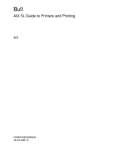
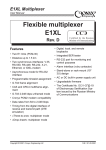
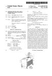
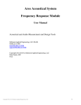
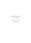
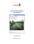
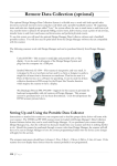
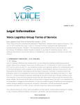
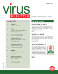
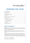
DVB receiver VP-1020 Satellite Internet access Satellite Internet Access and Digital Satellite TV reception PCI-adapter Installation and Operations Guide Copyright © 2003 Cronyx Engineereing Revision 1.1, December 2003 DVB VP-1020 Receiver Contents Contents .......................................................................................................................... 2 Introduction .................................................................................................................... 4 Summary of satellite Internet access principles .......................................................... 5 Brief glossary............................................................................................................... 7 Satellite ..................................................................................................................... 7 DVB .......................................................................................................................... 7 LNB .......................................................................................................................... 7 Switch, positioner, DiSEqC, switching and control procedures .............................. 7 Transponder, frequency and polarization, symbol rate, FEC................................... 8 PID and network address ........................................................................................ 10 Technical and operational characteristics..................................................................... 11 Delivered items............................................................................................................. 13 Minimum requirements ............................................................................................. 14 Minimum system requirements for satellite Internet access: ................................. 14 Minimum system requirements for viewing satellite TV programs: ..................... 14 Installation .................................................................................................................... 15 Installation of the adapter into the computer............................................................. 15 Drivers and software installation............................................................................... 16 Installation of the drivers and software using the installer program ...................... 17 Installation of the drivers without using the installer program .............................. 23 Using “Cronyx SaNet” ................................................................................................. 26 Functions.................................................................................................................... 26 The control utility software allows you to:............................................................. 26 Control utility software description........................................................................... 27 Main SaNet Window .............................................................................................. 27 Description of the “Tuner” panel, control of the satellite and transponder list...... 30 Adding/editing satellite parameters, changing converter parameters .................... 31 Adding/editing transponder characteristics ............................................................ 32 Description of the “Data streams” panel ................................................................ 33 Meaning of icons in the data stream list ................................................................. 33 Description of the “Network address” panel .......................................................... 35 Description of the “Security” panel........................................................................ 37 Description of the “Statistics” panel....................................................................... 41 Description of the “Activation” panel .................................................................... 45 Initial setup, activation .............................................................................................. 46 Entering satellite and transponder information ...................................................... 46 Monitoring the received signal ............................................................................... 47 Selecting streams for date reception....................................................................... 48 Activation of the SaNet software............................................................................ 49 Configuring network address (optional)................................................................. 50 2 Copyright © 2003 Cronyx Engineering DVB VP-1020 Receiver Setting up security options ......................................................................................50 Monitoring the data being received.........................................................................50 Frequently encountered problems and their solutions ..................................................52 Appendix DVB terms and abbreviations reference ......................................................53 “Cronyx Engineering” Company technical support service: Phone: +7 (095) 946-99-90 [email protected] E-mail: Website: http://www.cronyx.ru ftp://ftp.cronyx.ru “Cronyx Engineering” Company office and sales department: Phone: +7 (095) 742-17-71 Fax: +7 (095) 742-17-73 E-mail: [email protected] Prices: http://www.cronyx.ru/price Please, send your suggestions and comments concerning this Guide and operation of software to [email protected] Sincerely yours, Leonid Yuriev, Cronyx Engineering. Copyright © 2003 Cronyx Engineering 3 DVB VP-1020 Receiver Introduction The Cronyx DVB VP-1020 adapter is designed for reception of digital satellite channels, primarily for satellite Internet access, and reception of digital video and audio programs. In the low-budget satellite receiver class, the VP-1020 adapter has one of the best price/quality ratios in the market. The supplied software allows you to maintain a list of satellites and transponders, automatically detecting active data streams. The unique capabilities of the adapter include tracking of signal quality, error level, and received data baud rate, the mechanism to detect illegal use of your account, and a built-in incoming IP-packet firewall. Visual signal control allows you to quickly evaluate and eliminate any negative factor influence. External view of Cronyx DVB VP-1020 adapter: The adapter has a hardware QPSK demodulator, a self-adjusting FEC decoder, and the Reed-Solomon error correction unit. The adapter tuner has an additional “antenna” output, which allows to daisy chain several DVB-receivers, or to use the VP-1020 adapter in combination with other equipment. 4 Copyright © 2003 Cronyx Engineering DVB VP-1020 Receiver Summary of satellite Internet access principles The scheme of satellite Internet access may be described as follows: You, as a user, have a set of equipment designed for the reception of signals from a geostationary satellite, and some “ground-based” Internet connection; When you request some information from the Internet, your request “goes from” you through the “ground-based” communication link, for instance to the closest Internet Service Provider; The information supplied in response to your request does not go directly to you, but to your “satellite” provider first; The satellite provider redirects the information addressed to you to its satellite, and the satellite retransmits the information to you; You receive the incoming information using your satellite antenna and Cronyx DVB VP-1020 adapter; DVB-based satellite Internet access: Geostationary Satellite Transmitter Receiver Internet Network Server Your Computer Modem Internet Provider Since the volume of received information is usually much higher, than that of transmitted information, and the speed provided by the satellite is much higher Copyright © 2003 Cronyx Engineering 5 DVB VP-1020 Receiver than that of the inexpensive “ground-based” channel, you receive a much wider range of capabilities and much higher quality of service for the same price. Satellite Internet access information transmission technology uses the DVB – a set of standards and technologies used for modern digital television. This explains the possibility to use the same equipment for both “satellite” Internet access, and for viewing digital “satellite” television programs. 6 Copyright © 2003 Cronyx Engineering DVB VP-1020 Receiver Brief glossary Satellite Geostationary satellite – a satellite with the circular orbit lying in the same plane, as the Earth equator, and which orbits the Earth in the same direction and with the same angular speed as the Earth itself rotates, allowing the satellite to remain practically motionless with respect to the Earth. This Guide uses the term “Satellite” also to denote a configuration item. For example, “Satellite list”. DVB Digital Video Broadcasting – a set of standards, technologies, and conventions for the transmission and reception of digital signals, particularly, for digital satellite television. This is also the name of the organization specializing in development, coordination, and dissemination of the corresponding documents. LNB Low Noise Block downconverter – a converter, which transforms the received radio waves into an electric signal, amplifies this signal, and performs frequency conversion. The conversion of high frequencies (3.40 to 3.70 GHz for the “C”band, and 10.75 to 12.75 GHz for the “Ku”-band) into relatively low frequencies (0.95 to 2.15 GHz), allows transmitting signals to the receiver over an “antenna” cable without losses, and makes the design of the receiver much cheaper. Usually the LNB with one or two feedhorns is assembled into a single unit, and placed into the focus of the antenna. These units are frequently called “heads”, or “LNBF”s. Heads with multiple feedhorns allow receiving signals of different polarizations, and sometimes have two LNBs installed, allowing receiving both bands (“C” and “Ku”). Such “complex” heads are equipped with control circuits for polarization and band selection. Switch, positioner, DiSEqC, switching and control procedures Switch – a device allowing to selectively connect one of the several antennas to the receiver input. The antennas being switched may be correspondingly directed onto different satellites. It would be more correct to say that the switch allows performing a selection between several LNBs, since it is sometimes used to select LNBs of the same antenna. Copyright © 2003 Cronyx Engineering 7 DVB VP-1020 Receiver Positioner – a more complex device designed for alignment (rotation) of antenna. In other words, the positioner, in combination with antenna actuator, allows using the same antenna to receive signals from all available (visible) satellites. DiSEqC – a protocol, according to which receiver sends commands to switch and positioner. There are several DiSEqC versions, none of which has been standardized yet, which leads to certain problems. Currently, the following versions are most frequently used: “Mini DiSEqC” and “DiSEqC 1.0” – are used to control switches, that is, to switch between antennas; “DiSEqC 1.2” – is used to control positioners, that is to align the antenna; “22 kHz”, “Data Burst”, “Tone Burst”, “Low Voltage”, “High Voltage” – all these are the LNBF unit control methods: polarization switching, band selection (by selecting one of the two LNBs), and sometimes selection of one of the two antennas. The “low voltage” means voltage of 11 to 14 Volts, and the “high voltage” means voltage of 16 to 18 Volts. When using voltage control the LNB supply voltage may either have a “low” level, or a “high” level, or not be supplied at all. When using the “22 kHz” method, a continuous 22 kHz tone is switched on. Turning on “Data Burst” or “Tone Burst” leads to a continuous transmission by pulse modulation of the 22 kHz tone, of “units” or “zeroes” respectively. So, the “22 kHz”, “Data Burst”, and “Tone Burst” settings are mutually exclusive. Currently the de facto standard is the voltage polarization switching (horizontal/left or vertical/right), and 22 kHz tone band selection (“C” or “Ku”). Transponder, frequency and polarization, symbol rate, FEC Satellite transponder – on board radio device, including receiving antenna, receiver, frequency converter, transmitter, and transmitting antenna, and designed for signal retranslation within a certain frequency band. More frequently, however, the term transponder related to the stream of information, transmitted from the satellite using a certain frequency. In other words, a “satellite” transponder can retransmit, using different frequencies, and different polarization, several streams, which users also frequently call “transponders”. It is this meaning that we apply the “transponder” term to in this Guide. 8 Copyright © 2003 Cronyx Engineering DVB VP-1020 Receiver Formerly, before the development of technologies, there was no such confusion, because a “satellite” transponder could only retransmit a single information stream at a single carrier frequency. Frequency – the amount of full oscillation periods within a unit of time. The frequency used for modulation and data transmission, is called the carrier frequency. Polarization – this term may be described as the position of electric and magnetic component vectors of electromagnetic field with respect to the surface of the Earth. The polarization property of radio waves is used for the space division of radio signals. Thus, using different polarization for the reception and transmission channels, it is possible to simultaneously receive and transmit signals at the same carrier frequency, without mutual interference. The “horizontal”, “vertical”, “left circular”, and “right circular” polarization types are distinguished. Depending on the band, the signal may be transmitted using “horizontal” or “vertical” polarization, or “left circular” or “right circular” polarization. The “C”-band uses vertical or horizontal polarization, and the “Ku”band usually employs circular that is “left” or “right” polarization. Symbol rate – the number of symbols transmitted during a unit of time. The “symbol” means a change of signal properties according to the modulation method used. In other words, the “symbol rate” term means the same as the “baud rate” term. Each symbol may carry a certain volume of information, depending on modulation. The QPSK modulation is used in DVB technologies when transmitting information from satellites, and each “symbol” carries two bytes of information. FEC (Forward Error Correction) – this is a method of redundant information coding, which allows correcting separately occurring errors. The FEC code is specified by the ration of two digits (FEC RATE), such as 1/2 or 3/4. The digits specify the level of redundancy introduced into the information stream. The more the redundancy level, the more errors may be corrected, and the more information must be transmitted. So the most “reliable” level is 1/2, but it requires transmitting twice the amount of information, and for example, the 7 to 8 code requires transmitting only 15% more information. Copyright © 2003 Cronyx Engineering 9 DVB VP-1020 Receiver PID and network address Each satellite has several “satellite” transponders, and each of those may retransmit one or more information streams (“informational” transponders). These streams mat carry both analogue and digital information. Each digital transponder transmits data in small parts (packets), and each packet is assigned a number – “PID”, or Program Identifier. The sequence of such packets having the same PID makes up a “data stream”, so we may say that a digital “informational” transponder has several data “subchannels”. Each of these streams may carry its “own” data independently from the others, for example: program schedule, digital video, digital audio, captions, Internet data, etc. Each information type has its own format, clearly specified by the standard. If a “data stream” is used to transmit Internet information, then data inside the stream are transmitted in “sections” which have the recipient address. Thus, a single stream may be used to deliver information to several addresses. According to the “network address” specified, the data addressed to you are selected (filtered) from the stream. To make the description more intuitive, let us represent the satellite as a “city”, with many highways leading in, and out of it. The traffic on each of the highways is one-way, but on multiple levels. Each of these highways represents a “satellite” transponder, and each of the levels represents one of the “informational” transponders. Each level contains several traffic lanes, which are assigned PIDnumbers, - these are “data streams”. The cars moving along each lane are transport packets, or DVB-packets. Each car carries a load according to the waybill, and the invoice – these are data sections. Each load has a destination address – this is the “network address”. 10 Copyright © 2003 Cronyx Engineering DVB VP-1020 Receiver Technical and operational characteristics Network capabilities: Support of Multi-protocol Encapsulation (MPE) protocol; LLC SNAP support; IP-protocols supported: all IPv4 and IPv6; Reception of packets up to 65,535 bytes in size (MTU); Controlled broadcasting and multicasting filtering on the MAC-level; Controlled broadcasting and multicasting filtering on the IP-level; Controllable blocking of potentially unsafe IP-packets (firewall); Controllable mechanism for the detection of illegal use of the access service; Unicast and multicast routing; Compliance with the ETSI 301.192 Standard; Monitoring: Graphical display of signal level, number of errors, and reception speed for the last 10 minutes; DVB-stream reception statistics; IP-stream reception statistics; Indication of the relative error level: average, and snapshot error levels, detected by the DVB-decoder, total error level (including uncorrected errors, data errors, and CRC errors); DVB error, CRC error, and blocked IP-packet counters; Total received data volume information; Receptions, speed, snapshot and average signal level, signal lock reliability, FEC rate, and quality of service evaluation indications; Display of active data streams (PIDs) in the transponder; Tuner: Reception frequency: 950 to 2150 MHz; Automatic sensitivity adjustment range: -65 to 25 dBm; Input and output sockets: F-type 75 Ohm; Decoder (QPSK & FEC): QPSK filter: with a cosine square root front edge, and a 0.35 falling edge; Symbol Rate: 1 to 45 Msps; MCPC and SCPC support; FEC decoding: automatic; Copyright © 2003 Cronyx Engineering 11 DVB VP-1020 Receiver Converter and switch control: LNB supply voltage: selectable between 13 or 18 Volts, with a 400 mA current, overvoltage and short circuit protection; DiSEqC support: 1.0, 1.1, 1.2; 22 KHz dish and LNB control, Data Burst and Tone Burst support; Demultiplexing: Data reception rate: up to 78.75 Mbit/s; Maximum number of simultaneously used streams (PID filtering sections): 8192; Stream capture: PES and TS; Filtering: PES and TS; Error control: CRC, Checksum32, parity; PCI interface: Compliance with the PCI 2.2 Bus Standard; Peak transfer rate (in the bus-master mode): up to 132 Mbytes/s; Bidirectional FIFO; Other: Drivers and software for Windows 2000/XP/2003 operating systems; Easy “Plug-and-Play” installation; Sharing IRQ for prevention conflict with other devices; Dimensions (excluding mount and PCI-contacts): 125 x 95 mm (PCI full profile); Operating conditions: Operating temperature: -5 to 65°C; Storage temperature: -55 to 85°C; Humidity: 0% to 95% (without condensation); 12 Copyright © 2003 Cronyx Engineering DVB VP-1020 Receiver Delivered items Software and drivers are supplied for Windows 2000, Windows XP, and Windows Server 2003 operating systems only. Outdated operating systems, such as Windows 3.1, Windows 95, Windows 98, Windows Me, Windows NT 3.51, and Windows NT 4.0 are not supported. The Linux OS driver and software supply is on the planning stage. The delivered items include: VP-1020 PCI-adapter card; The driver and software CD-ROM; This Guide; Box package; Attention: The WinDVB program documentation is supplied in English only, and the program is not supported by the “Cronyx Engineering” company. In the future the program will be replaced by a more advanced software package. If you have any problems and/or trouble using WinDVB, contact the support department of InterVideo company, or consult the built in Help system (in English). Copyright © 2003 Cronyx Engineering 13 DVB VP-1020 Receiver Minimum requirements Minimum system requirements for satellite Internet access: PC-platform computer, with a version 2 PCI-bus (2.0, 2.1, or 2.2 specifications); An empty PCI-slot with a 5 Volts supply, and the capability to hold a fullscale PCI-adapter; Intel Pentium II, or compatible CPU; 64 megabytes of RAM; CD-ROM drive; 800 x 600, 256 color video adapter; Windows 2000 or subsequent version (Windows XP, Windows Server 2003, etc.) operating system; Minimum system requirements for viewing satellite TV programs: Intel Pentium II or compatible CPU with at least a 750 MHz clock frequency; 128 megabytes of RAM; 800 x 600, True Color video adapter; Windows 2000 (or subsequent) operating system, DirectX 8.1 (or higher); Sound card; 14 Copyright © 2003 Cronyx Engineering DVB VP-1020 Receiver Installation Software and driver installation may be performed either before, or after PCIadapter installation into your computer. In any case you must log on into the system with administrator rights. You may install several VP-1020 adapters into a single computer, but only one of those will be operable (serviced by software). Driver and software installation is performed using the setup.exe program, located in the root folder of the supplied CD-ROM. If the adapter is not installed before running setup.exe, then the installer will not install drivers, and will only specify their location to Windows. Then, after the adapter is physically installed, Windows will detect new hardware device, and prompt you to continue driver installation. Attention: You may install adapter system drivers manually, or trust the installer to do this. However, installation of the rest of the software may be performed by the installer only. Installation of the adapter into the computer Contact technical support if you are unable to do this on your own. 1. 2. 3. 4. Turn off the computer; Open the computer case; Install the adapter into a suitable PCI-slot, and fix it. Connect the “antenna” cable (LNB output), to the adapter socket marked “LNB-IN”: 5. If required, connect the “antenna” output of the adapter, marked “LNB-OUT”, to other equipment; 6. Close the computer case; 7. After this you need to install drivers and software; Copyright © 2003 Cronyx Engineering 15 DVB VP-1020 Receiver Drivers and software installation Turn on the computer, wait for Windows to load, and log on into the system with administrator rights. If the adapter has already been installed into the system, then Windows detects a new device, and prompts you to install drivers for it. Windows reports that a new hardware device is found: The “Found New Hardware Wizard” is started automatically: After this you may install the drivers manually using the “Found New Hardware Wizard, or press the “Cancel” button to exit the Wizard, and simply run the setup.exe installer. 16 Copyright © 2003 Cronyx Engineering DVB VP-1020 Receiver Installation of the drivers and software using the installer program To install drivers and software using the installer program, exit the “Found New Hardware Wizard” by pressing the “Cancel” button, and run the setup.exe, located in the root folder of the CD-ROM disk supplied with the adapter. When you run the installer program, a Welcome screen appears, and then you must follow the installer instructions. An installer Welcome screen: Copyright © 2003 Cronyx Engineering 17 DVB VP-1020 Receiver Important last minute “readme” information, read it carefully: Destination folder selection screen: Currently, the WinDVB program, developed by the InterVideo company, is included in the package for viewing satellite TV channels. Since this software does not comply with our quality requirements, we do not recommend you to use it. For 18 Copyright © 2003 Cronyx Engineering DVB VP-1020 Receiver the same reason we do not support WinDVB, and do not supply any other documentation, except the original online English documentation supplied by the developer company. In future we will supply another software package for viewing TV channels and video programs. Select the required components; by default, only components required for satellite Internet access are installed. Component selection screen: Copyright © 2003 Cronyx Engineering 19 DVB VP-1020 Receiver The last screen, before the installation starts: Installation progress screen: During drivers installation, depending on Windows settings, a screen warning you that the software does not contain a digital signature may appear. 20 Copyright © 2003 Cronyx Engineering DVB VP-1020 Receiver If such warnings appear, you must allow drivers installation by pressing the “Yes” button. Otherwise the drivers will not be installed, and you will have to install them manually. The installer will also warn you about this. Possible warning information: System warning that the driver package does not contain a digital signature, the screen may look different in your version of Windows: Copyright © 2003 Cronyx Engineering 21 DVB VP-1020 Receiver System warning that a specific driver does not contain a digital signature, the screen may look different in your version of Windows: Final installation completion screen: The installation is complete. In order to obtain satellite Internet access, you should run the “Cronyx SaNet” program, apply the required settings, and enter the activation code. 22 Copyright © 2003 Cronyx Engineering DVB VP-1020 Receiver Installation of drivers without using the installer program You may install the drivers without using the installer program, by running the “Found New Hardware Wizard”. If you have decided to install the drivers this way, then follow the instructions of the “Found New Hardware Wizard”. If required, use your Windows Guide, and the built-in Help system. Found New Hardware Wizard: In order to search for drivers, insert the CD-ROM disk supplied with the adapter, and tell the Wizard, that the drivers are located on it. Copyright © 2003 Cronyx Engineering 23 DVB VP-1020 Receiver Specifying the location to search for drivers: The “Found New Hardware Wizard” reports that is has found a compatible driver: 24 Copyright © 2003 Cronyx Engineering DVB VP-1020 Receiver The “Found New Hardware Wizard” reports that it has completed the driver search and installation procedure: After having installed the drivers, you must install the software by running the setup.exe file, located in the root folder of the CD-ROM disk supplied with the adapter. See page 17 for more details. Copyright © 2003 Cronyx Engineering 25 DVB VP-1020 Receiver Using “Cronyx SaNet” Functions The “Cronyx SaNet” program is designed to set up and control the “Cronyx DVB VP-1020” receiver, monitoring data reception, and set security options. The unique distinctive capabilities of the adapter include the graphical tracking of signal quality, error level, and received data baud rate during the last 10 minutes, the mechanism to detect illegal use of your account, and a customizable built-in incoming IP-packet firewall. Visual signal parameter control allows you to perform the most precise antenna alignment, and quickly evaluate and eliminate the effects of possible negative factors. The control utility software allows you to: Maintain a list of available satellites, and transponders present on each of the satellites; Maintain a list of PID-streams from each transponder, and select the used streams; Switch between several antennas; Select the reception of one of the transponders; Automatically detect active data streams; Monitor the most important communication quality parameters (signal level, error level, number of losses); Monitor data reception (number of IP-packets, amount of information received, data reception speed); Set up options to block the reception of potentially unsafe data; Optionally: set the network address to be used for filtering sections of data; The Cronyx SaNet program has a clear, intuitive interface, complying with the Windows GUI recommendations. 26 Copyright © 2003 Cronyx Engineering DVB VP-1020 Receiver Control utility software description Main SaNet Window The SaNet program detects the Windows localization settings during start up, and, depending on this information, starts a Russian or English interface. The main SaNet window name always shows the name of the satellite and the transponder, for which the receiver is currently configured. Just below the window name, in the upper line the receiver status and signal quality information are shown. In the upper left corner you may see the volume of data received during the current session (from the moment the control program was started). Main Cronyx SaNet window: The following four buttons are always available in the bottom area of the window: “Turn off & Quit” – Turns off the receiver, completes the current communication session, and closes the SaNet program. You must run the SaNet program again to resume; Copyright © 2003 Cronyx Engineering 27 DVB VP-1020 Receiver “Allow changes”, ”Disable changes” – Allows protecting the user from inadvertently changing reception parameters, or the currently received transponder; “Cancel” – Cancels the last changes; “Lock”, “Switch”, ”Done” – Applies the parameter changes, switches the receiver to another transponder, and/or locks on the signal. In the “Done” state the SaNet program is minimized to a taskbar tray icon. Most of the window is occupied by control and informational “panels” arranged as “tabs”. There are six panels, but not all of them may be accessible to you: “Tuner” – designed to maintain the satellite and transponder list, set LNB parameters, and antenna switch method; “Data streams” – designed for the selection of streams (PIDs) into which the information is translated; “Network address” – designed to specify a network address (filtering MAC-address), may be available as an option only after entering the activation code; “Security” – designed to specify network security related options (available only after entering the activation code); “Statistics” – displays signal level and quality information, received information volume, statistics, etc.; “Activation” – designed to enter the activation code, displays information about available options; 28 Copyright © 2003 Cronyx Engineering DVB VP-1020 Receiver All SaNet configuration information is stored in the CronyxSaNet.ini file, which is located in the same folder with the CronyxSaNet.exe executable file. If the user starting SaNet does not have the rights to change the configuration file, then any configuration changes will not be allowed. If you have already configured SaNet, then, when you start it next time, the program will automatically turn on the reception for the selected transponder, disable changes, and minimize itself to a taskbar tray icon. In other words, it tries to attract as little attention, as possible. SaNet minimized to the taskbar tray: Depending on the current state, the taskbar tray icon may have different appearances: “Blue antenna” – Normal signal reception; “Red antenna” – No signal, or system error; “Grey antenna” – The receiver is not configured, or turned off; Copyright © 2003 Cronyx Engineering 29 DVB VP-1020 Receiver Description of the “Tuner” panel, control of the satellite and transponder list This panel allows you to manage the list of satellites and transponders: delete and add new, view and change the parameters of existing satellites, specify a satellite and transponder you want to switch to. The “Tuner” panel The left area contains the list of satellites and transponders, and the right area contains the parameters of the selected satellite and transponder. When viewing, you may select a transponder of any satellite, the program will not perform a switch between satellites and receiver reconfiguration, but will display the information about the selected object in the right area of the window. To switch to the selected transponder, you should press the “Lock”/”Switch” button. And, if changes were previously blocked, then you must press the “Allow changes” button to enable switching. In order to cancel inadvertent or undesired changes, you may press the “Cancel” button. 30 Copyright © 2003 Cronyx Engineering DVB VP-1020 Receiver Adding/editing satellite parameters, changing converter parameters In order to add a new satellite to the list, press the “Add satellite” button; to change parameters of an already entered satellite – select it from the list in the left area of the window, and press the “Change” button. The satellite parameter entry and edit window opens above the main SaNet window. Add/edit satellite parameters window: The program checks the correctness of the specified parameters, and highlights unacceptable values. The “Frequency #2” value is unacceptable and highlighted: Attention: For the opportunity to use all existing methods of connecting several LNBs to a receiver, the antenna and LNB frequency switching methods may be specified independently for each satellite. Despite the fact that it is illogical in case of a single LNB. Copyright © 2003 Cronyx Engineering 31 DVB VP-1020 Receiver Adding/editing transponder characteristics In order to add a new transponder, select the required satellite from the left area of the window, or one of its transponders, and press the “Add transponder” button, and in order to change parameters of an already entered transponder, select it from the list and press the “Change” button. The transponder parameter entry and edit window opens above the main SaNet window. Transponder parameter entry and edit window: Same as in the case with satellite parameter entry, the validity of values is controlled, and unacceptable values are highlighted. The “Symbol rate” value is invalid, and is highlighted: If the Viterby (FEC) code is specified incorrectly, and/or the decoder can detect it automatically, then the automatic scan is switched on. 32 Copyright © 2003 Cronyx Engineering DVB VP-1020 Receiver Description of the “Data streams” panel The “Data streams” panel is designed to specify the particular data streams transmitted over the transponder, which are used for data transmission. The “Data streams” panel shows the information corresponding to the transponder currently selected from the “Tuner” panel. If a transponder, to which the receiver is currently tuned, is selected from the “Tuner” panel, then the stream list will also show all currently active transponder streams (PIDs). During reception, the transponder is constantly being scanned for the presence of active streams, and the list shows the current state. The “Data streams” panel Meaning of icons in the data stream list “Question mark” – Newly detected stream with an unspecified format; “Grey star” – Automatically set stream for multicast reception, the stream is inactive, the system is waiting for data to come; “Yellow star” – Automatically set stream for multicast reception, the stream is active, data are coming; Copyright © 2003 Cronyx Engineering 33 DVB VP-1020 Receiver “Grey lamp” – Inactive stream, the system is waiting for data to come; “Yellow lamp” – Active stream, data are coming and being analyzed; “Blue lamp” – Active, but unused data reception stream; In order to receive data from a particular stream, you have to assign the “Multiprotocol Encapsulation” (MPE) format to the stream. To do this, you may use the “Change” and/or “Add” buttons. You may directly connect of disconnect a stream by clicking the corresponding “check mark” in the stream list. Data stream parameter entry and edit window: Beside this, SaNet has the capability to automatically connect and disconnect the streams used for multicast transmissions. The corresponding mechanism is controlled by the “Auto-set multicast PIDs” checkmark. Attention: Your satellite provider must inform you, which streams you must use, and whether you should enable the “Auto-set multicast PIDs” setting. 34 Copyright © 2003 Cronyx Engineering DVB VP-1020 Receiver Description of the “Network address” panel The “Network address” panel is optional, and may be inaccessible, if your activation code provides for a fixed network address only, or it may be entirely absent in your software version. The “Network address” panel The network address (MAC address) is used to filter data directed to you from the whole information stream generated by the selected streams. Attention: To establish a connection with you chosen satellite provider, it must inform you of the network address (MAC address) of your adapter. The network address is printed on the label, next to the activation code. After entering the activation code, you may also see the network address in the “Identifier” field of the “Activation” panel. Your satellite provider must also inform you of the network address setting type to use. Copyright © 2003 Cronyx Engineering 35 DVB VP-1020 Receiver The following network address setting options are available: “From network adapter” – the address of the selected network adapter is used for filtering; “By IP-address in network” – the address, based on the IP-address of the selected network adapter, is used for filtering. The network address is obtained by adding the “00:02” prefix to the four bytes of the IP-address of the selected network adapter; “By IP-address of dialup connection” – the address, based on the IPaddress of the selected dialup connection, is used for filtering. Since the dialup IP-address is available only after the connection has been established, the network address is also generated only after the establishment of the connection. Same as in the previous case, the network address is obtained by adding the “00:02” prefix, to the four bytes of the IP-address of the selected dialup connection; “Manually” – a custom network address which you enter will be used; “By custom IP-address» – the address, formed on the basis of a custom IPaddress which you enter, is used for filtering. The network address is obtained by adding the “00:02” prefix to the four bytes of the IP-address entered; 36 Copyright © 2003 Cronyx Engineering DVB VP-1020 Receiver Description of the “Security” panel From the “Security” panel you may control the settings affecting network information security. SaNet does not have any advanced protection features, built into many specialized products. Nonetheless, the basic security features built into SaNet, allow you to easily close many dangerous ways the hackers might use to obtain access to your computer. The “Security” panel with default settings: Security control options (this information is for experienced users and specialists only): “Accept incoming broadcast data sections” – allows you to enable or block the reception of DVB data sections with the “FF:FF:FF:FF:FF:FF” broadcast receiver address. “Accept incoming multicast data sections” – allows you to enable or block the reception of DVB data sections with the “01:??:??:??:??:??” multicast receiver address. “Accept incoming broadcast IP-packets» – allows you to enable or block the reception of IP-packets with the “255.255.255.255” broadcast receiver address. Copyright © 2003 Cronyx Engineering 37 DVB VP-1020 Receiver “Accept incoming multicast IP-packets» – allows you to enable or block the reception of IP-packets with a multicast receiver address from “224.0.0.0” to “231.255.255.255”, inclusive. “Accept incoming ICMP queries” – allows you to enable or block the reception of incoming ICMP queries. Using this option allows you to hide your computer, and the possible network connected to it, from being queried from the outside using the ICMP protocol. “Enable only basic protocols” – optional, and may be unavailable (always enabled), if you activation code does not provide for the corresponding capability. The following are allowed with this option turned on: Data sections without the LLC (Logical Link Control) only; IP protocol Version 4 only; IGMP (Internet Group Management Protocol), TCP (Transmission Control Protocol), UDP (User Datagram Protocol), and ICMP (Internet Control Messages Protocol) only; IP-packets without IP-options only (20 bytes header size), as a consequence, “Source Routing”, “Record Route” and other rarely used capabilities are prohibited; All other data packets are prohibited, and the “Blocked” counter on the “Statistics” panel increased when they are. Using this option allows to protect your computer against some types of advanced network attacks and hacker tricks. The probability of problems arising when this option is checked is extremely low, and according to our evaluations, problems may arise only in rare cases when using specialized software. “Enable incoming connections only for safe ports” – the following is allowed when this option is checked: Incoming data over already established TCP-connections; Incoming TCP-connections to non-privileged ports (with numbers above 1023); Incoming TCP-connections to ports number 113 (auth / Identification Protocol), and 20 (ftp-data / File Transfer Protocol, Data Stream); Incoming UDP-datagrams over non-privileged ports (with numbers above 1023); Incoming UDP-datagrams over ports number 53 (DNS / Domain Name Server), and 123 (NTP / Network Time Protocol); All other IP-packets are prohibited, and the “Blocked” counter on the “Statistics” panel increases when they are blocked. Using this option allows you to protect your computer against the most widespread types of network attacks, make it impossible to use many knows vulnerabilities contained in operating systems and widely used software 38 Copyright © 2003 Cronyx Engineering DVB VP-1020 Receiver applications. There is a low probability of problems arising when this option turned on, but such problems are possible with some software applications. If you do not have adequate experience in network security, it is recommended to turn this option on, and avoid using software applications (or components), which cause problems. When blocking an IP-packet, all of its components are blocked, which makes it difficult to use some dangerous types of network attacks. “Illegal usage detection” – this option allows you to employ a mechanism designed to detect illegal usage of your account with the satellite provider in case when the computer is not used as an incoming gateway for a network. When this option is checked, the network driver traces IP-packets not corresponding to TCP-connections opened on you computers, or the UDP-sockets being listened. Such IP-packets may be received only when someone else creates parallel network activity. Right-clicking on the “Security” panel brings up a menu containing three items: “Recommended settings”, “Turn off security”, and “Show incoming streams”. Correspondingly, it is possible to quickly switch to “default” security settings, completely turn off the protection, or look through information on data streams currently being received from the Internet. The window showing data streams being received from the Internet: *Values in the “Volume” column are calculated without taking into account possible datagram fragmentation Suppose that someone unauthorized, who gained access to your account, sends requests from his computer to some server, and the server responds to his requests. Since the data stream from the satellite provider to you and to the violator is the same, SaNet will also “notice” the server replies to requests not send by you. 39 Copyright © 2003 Cronyx Engineering DVB VP-1020 Receiver When such situation is detected, the corresponding message is displayed, based on which you may communicate with your satellite provider. Warning message example: *Values in the “Volume” column are displayed without taking into account possible datagram fragmentation To obtain more flexible and customizable protection, we can recommend you to use such well-known products as: “Outpost Firewall” http://www.agnitum.com, and “Norton Internet Security” http://www.symantec.com. Using these and other products, you may be sure that there are no conflicts, and that these products are fully compatible with SaNet. 40 Copyright © 2003 Cronyx Engineering DVB VP-1020 Receiver Description of the “Statistics” panel The “Statistics” panel displays all information related to the level and quality of the signal being received, the information received, and the software version. The upper area of the panel graphically shows main communication quality parameters for the last two minutes, and below are different information fields and counters. The “Statistics” panel You must note, that the Cronyx DVB VP-1020 adapter does not belong to the measurement equipment class, and is not designed to measure, analyze or diagnose satellite equipment. So, such values as “Signal level”, “Quality of Service”, “Errors ratio” may differ for different adapters under same conditions, and cannot be transformed to EIRP, or other formally defined characteristics. The upper area of the diagram shows the following: In blue color – Signal level “from the point of view” of the adapter, on a linear scale from 10% to 100%; In white color – Signal quality “from the point of view” of the adapter, on a linear scale from 10% to 100% In red color – General errors ratio, on a logarithmic scale from 0% to 50%; Copyright © 2003 Cronyx Engineering 41 DVB VP-1020 Receiver In green color – Data reception speed, logarithmic scale from 0 to 1 Mbytes per second; The information is refreshed once per second. The diagram has two horizontal scales with the same scale ratios for your convenience, the upper moving together with the picture, and the lower one staying fixed. The largest points of the scales correspond to minutes, the smallest correspond to tens of seconds, and one pixel of the picture corresponds to one second. The signal level measured by the adapter also includes interference and noise, and may have non-linear automatic gain control. So, you should not strive for the maximization of the signal level when performing any adjustments. It is more desired to obtain the minimum possible error ratio together with a high signal level and an even shape of the graph. If the signal graph contains clear periodic “sinusoidal” processes, this, in most cases, is the evidence of the heterodyne frequency sweep in the LNB (or the satellite transponder). Sometimes this effect may appear when the antenna swings with a large period. Information fields and counters, left side: “UI version” “Driver version” “Quality of Service” “Average Speed” – Adapter driver version; – A percentage evaluation of the quality of service, taking into account all errors; – The first field shows DVB stream averaged total bandwidth, the second – data reception speed, averaged over the last few seconds; “Losses Ratio” – The first field shows the losses by packets error, the second – the losses in tuner demodulator, and the third – result losses level; “Signal Level” – Signal level averaged over the last few seconds; “Signal Quality” “Current FEC rate (Viterby)” “Signal lock level” 42 – The user interface version (of the control program); – Signal quality (signal/noise ratio) averaged over the last few seconds; – The Viterby code (FEC Rate) used; – Signal lock reliability in percent; Copyright © 2003 Cronyx Engineering DVB VP-1020 Receiver Information fields and counters, right side: “DVB packets” “DVB bytes” – Total number of transport DVB-packets received from the moment the computer was turned on; – Total number of DVB-bytes received from the moment the computer was turned on; “IP packets” – Total number of all IP-packets received during the current communication sessions (after the control software has been started); “IP bytes” – Total volume of all IP-packets received during the current communication sessions (after the control software has been started); “Received packets” “Received bytes” – The number of received IP-packets, which were addressed to your computer during the current communication session (after the control software has been started), in three fields: the first field shows the number of broadcast packets; the second field shows the number of multicast packets; the third field shows the number of unicast packets; – The total volume of received IP-packets, which were addressed to your computer during the current communication session (after the control software has been started), in two fields: the first field shows the total volume of broadcast and multicast packets; the second field shows the total volume of unicast packets; Copyright © 2003 Cronyx Engineering 43 DVB VP-1020 Receiver Error counter: “Total received” “DVB packets errors” – Total cumulative volume of data received over the whole time of use; – The number of DVB-packet errors not corrected by the FEC code and the Reed-Solomon corrector, during the current communication sessions (after the control software has been started); “Data errors” – The number of data format errors detected during the current communication sessions (after the control software has been started); “CRC errors” – Number of “cyclical redundancy check” errors in the DVB-sections and IP-headers received during the current communication session (after the control software has been started); “Rejected” – Number of IP-packets blocked according to the configured security options during the current communication session (after the control software has been started); DVB packet errors – these are DVB Transport Stream Packet errors, which were impossible to correct using the FEC code and the Reed-Solomon algorithm. There must be no such errors during normal signal reception. If “DVB errors” appear regularly, this means that either the signal level is too low, or there are many errors resulting, for example, from heavy clouds, precipitations, or connector contact malfunction. Short-lived error “peaks” may be resulting from gusts of wind (deflecting the antenna), or birds and other objects flying over the antenna. Data errors – these are evident abnormalities in the structure of the received information. Usually such errors are resulting from repeated errors “unnoticed” by the correction circuits. Thus the number of data errors depends on the DVB error level. Such “data errors” are indicated when the appearance of the data section received does not comply with the ETSI 301.192 Standard. Thus it is “data errors” that will be registered when using streams carrying non-IP data. 44 Copyright © 2003 Cronyx Engineering DVB VP-1020 Receiver Attention: Rarely the displayed error level (percentage) may differ from the real one, this may result from incorrect system clock settings, or when the real symbol rate of the transponder is slightly different from the one specified. In case of any suspicion you may use, as a guide, the number of errors registered by the counters (DVB packet errors, CRC errors, data errors). Indication of the error level equal to a few hundredths of a percent, with no errors indicated by the counters, is an example of such a situation. Description of the “Activation” panel The “Activation” panel is designed to activate the software, it also shows activation-related information. After having entered the activation code, the informational fields will show information corresponding to the purchased license. See page 49 for more details concerning the activation process. The “Activation” panel Copyright © 2003 Cronyx Engineering 45 DVB VP-1020 Receiver Initial setup, activation After having installed the adapter into the computer, and the installation of the drivers and software, you must perform the following: 1. Specify the parameters, and tune to the required satellite and transponder; 1.1. Add the satellite you are going to use to receive data, or select it from the list; 1.2. Check and edit, if required, the LNB (converter) parameters, and antenna and/or LNB switching method, if you have more than one of those; 1.3. Add a transponder to the required satellite, or select it from the list; 1.4. Tune to the required transponder of the required satellite, and control signal level; 1.5. Select the required data streams; 2. Enter the activation code; 3. If required, enter the network address and/or change security settings; Entering satellite and transponder information Select the “Tuner” panel, the left area of which will show the list of satellites and transponders entered, and the right area of which will show the parameters of the selected (on the left) satellite and transponder. You should either find the required satellite and transponder in the list on the left, or enter new ones. Attention: The information about the satellite and the transponder must be provided to you by the satellite provider. The information about the LNB (converter), and antenna switching method (if you have more than one antenna) may be found in the equipment User’s Guide, or obtained from the technical service, which helped you install the equipment. In order to edit the satellite and transponder list, and change their parameters, use the corresponding buttons on the “Tuner” panel. LNB parameters may be accesses when editing satellite parameters. See page 30 for more details. 46 Copyright © 2003 Cronyx Engineering DVB VP-1020 Receiver Monitoring the received signal After you have selected the required satellite and transponder from the list in the left area of the “Tuner” panel, or have entered the parameters of the required satellite and transponder, you must set up the receiver, and check signal reception. Make sure that the required transponder of the required satellite is selected in the list in the right area of the “Tuner” panel, and that all parameters are correct. Then press the “Lock”/“Switch” button, which is the rightmost button in the lower area of the SaNet window. SaNet will then switch to the required antenna and/or LNB, and begin setting up the tuner to the selected transponder. Information about the current status will be displayed in the upper area of the SaNet window, for example: “Switching…”, then “Tuning…”, then “Signal lock…”. If all LNB parameters, antenna switching method, and satellite and transponder data are correct, all equipment is correctly connected, and you are located in the area of consistent reception, then signal will be locked very quickly, within 1-2 seconds. However, if reception is not consistent, or the antenna is not aligned correctly, or the satellite provider does not form the transponder with the required quality, then the signal capture process may continue for 10-15 seconds and more. During signal capture, adjustment and reception processes, you may monitor the signal level and other communication parameters. To do this, switch to the “Statistics” panel, after the new transponder switching and signal search and lock process has begun. As soon as the antenna is selected and the receiver is tuned, the “Statistics” panel will refresh and show the information. If required, the receiver adjustment continues after the signal has been locked. Notice the “DVB errors” counter, which displays the errors, which were not corrected by the correction circuits. If the number of errors is steadily increasing, then the quality of signal is insufficient, and, most probably, you will not be able to use satellite access to the full extent. You should then check the correctness of LNB, satellite and transponder parameters, alignment of the antenna and quality of cable connections. If signal level is low, or the number of errors is high, you may try to align the antenna more precisely, using the displayed signal level and error number graphs. But be very careful, and do not rotate the antenna for more than a few parts of a degree. You should not strive to obtain maximum signal level during antenna adjustment, because various interferences and noise also contribute to the measurement. You should try to obtain an even, flat signal level graph, and the minimum number of errors. Copyright © 2003 Cronyx Engineering 47 DVB VP-1020 Receiver See page 41 for more details about the meaning of information displayed in the “Statistics” panel. Selecting streams for data reception After having locked on the selected transponder, the “Data streams” panel will show the detected streams (PIDs). The active stream search is performed automatically and continuously, as long as the tuner is able to receive a satellite signal. In order to receive data, you must specify, which particular transponder streams carry the required information. The streams to select must be specified to you by the satellite provider, see page 33 for more details. 48 Copyright © 2003 Cronyx Engineering DVB VP-1020 Receiver Activation of the SaNet software Activation of the SaNet software may be performed at any time, but before activation, you will not be able to use SaNet for Internet access. Moreover, some options are unavailable without activation. Attention: The activation code (key) is a confidential piece of information. Your knowledge of the activation code confirms that you own a license, and, correspondingly, are entitled to use the “Cronyx SaNet” software. The divulgence and/or transfer, either voluntary, or unintentional, or as a result of theft, and the loss of the activation code is equal to the loss of the right to use the “Cronyx SaNet” software. For more details refer to the License Agreement. Proper functioning of two or more “Cronyx SaNet” copies having the same activation code is not guaranteed. This is also in violation of the “Cronyx SaNet” software usage license. In order to perform activation, switch to the “Activation” panel, and press the “Enter activation code” button. In the window that appears, enter your activation code. The activation code entry window: Depending on the software license purchased, and the software version, the activation code may have either basic, or extended format. The basic activation code consists of three alphabetic fields and one numeric, and the extended code consists of five alphabetic and two numeric fields. Depending on the activation code format, it must be entered in to corresponding fields of the form. 49 DVB VP-1020 Receiver After you have entered the activation code, and if all information has been entered correctly, the “Apply” button becomes accessible. After pressing the “Apply” button, the system will display the results. In most cases you must restart your computer to complete the “activation” process. Configuring network address (optional) If the software license purchased provides customizable setting of the network address, then, after having entered the activation code, the “Network address” panel becomes accessible. The network address (MAC address) is used to filter the data directed to you from the whole information stream generated by the selected streams. Attention: To establish a connection with your chosen satellite provider, you must be informed of the network address (MAC address) of your adapter. The network address is printed on the label, next to the activation code. After entering the activation code, you may also see the network address in the “Identifier” field of the “Activation” panel. Your satellite provider must also inform you about the network address setting type to use. See page 35 for more details. Setting up security options The Cronyx SaNet software has built in basic information security tools. This protection is not a panacea from all trouble, but allows you to protect yourself from many attack types, and make difficult many other hackers attempts. If you are not a specialist, or are not experienced enough in the field of network information security, then we recommend you to use the “default” settings. See page 37 for more details. Monitoring the data being received As soon as the receiver is tuned to the required transponder, and locks on the signal, you may use the “Statistics” panel to monitor data reception, and the “DVB packets” and “DVB bytes counters begin to increase. Note that the error level during consistent reception must not exceed a few fractions of a percent. If the required data streams are selected from the “Data streams” panel, then the “IP packets” and “IP bytes” counters also begin to increase. During this process, the “Data errors” counter must not increase more frequently than once in a few seconds. If, however, the “Data errors” counter increases continuously or periodically, then “redundant” streams are marked for use. Your satellite provider 50 DVB VP-1020 Receiver must inform you which streams to select. See page 33 for a more detailed information. During this stage you will most probably have to set up other software to be able to use satellite Internet access. For example, you may have to configure settings in the “Connection” panel of Internet Explorer, or create a VPN connection. Your satellite provider and Internet service provider must tell you what and how to configure. Now, as soon as data start to arrive to your address, the “Received packets” and “Received bytes” counters will display the volume of the received information, and the diagram will display the load graph. The “Total received” counter will also come alive. If, however, no data arrive in response to your requests, then you must check whether you have specified the correct network address (MAC address) to your satellite provider, and whether you have made correct network address settings on the “Network address” panel, see pages 35 and 49. See page 41 for more details about the meaning of information displayed on the “Statistics” panel. 51 DVB VP-1020 Receiver Frequently encountered problems and their solutions If no signal is locked on when tuning to a transponder, “No signal” message will be displayed in the status bar. If this situation arises for all satellites and transponders: 1. Check the integrity of the antenna, LNB unit, cables, and connectors; 2. Check antenna alignment; 3. Check whether the LNB is properly connected to the adapter; 4. Check, whether LNB parameters and the antenna switching method are properly specified; If this situation arises only with transponders of a single satellite: 1. Check, whether satellite and LNB parameters and the antenna switching method are properly specified; 2. Consult your satellite provider, it may be possible that the transmission from this satellite is temporarily down; If this situation arises only with a single transponder: 1. Check whether the transponder parameters are specified correctly; 2. Consult your satellite provider, it may be possible that the transmission from this transponder is temporarily down; The receiver properly receives the signal, the “DVB packets” and “IP packets” counters increase steadily, and the error ratio is insignificant. But no information is being received, and the “Received packets” and “Received bytes” counters are not changing. This situation my be due to several reasons: 1. You have incorrectly specified the network address of your adapter to the satellite provider, or the operator of the network provider has made an error; 2. You have incorrectly configured the network address or its method of configuration according to the information supplied by the satellite provider; 3. You have incorrectly specified the “data streams” which carry the required information; 4. It is possible, that transmission is temporarily disabled by the provider, in this case the selected streams on the “Data streams” panel become inactive; 52 DVB VP-1020 Receiver Appendix DVB terms and abbreviations reference 22 KHZ, 22 kHz tone switching Switching by a 22 kHz, is required for a two-band LNBF. Today it is a standard. In any case nowadays such heads are switched between the two bands using a 22 kHz tone signal (the supply voltage is used to switch older heads). Actuator An extendable dowel, like a lifting jack (and very similar in appearance to a shock absorber), which, by extending itself, moves the polar mounting of the dish. The dowel length may be 6", 8", 10", 12", 18", or 24". The worm shaft of the motor has a sensor (proximity or optical), which provides a certain number of pulses over a unit of dowel length. The greater this number is, the more precise is the positioning of the system. Az-El mount Azimuth fixed mount. The antenna is rigidly attached to the mount. It is simple to install, you may perform installation by yourself. Beam The polar pattern, defining the coverage area. This is the main characteristic of satellite transmission reception. Different transponders may have different beams. CAM, Conditional Access Module The module is constructed as a PCMCIA card slot, installed into CI-equipped receivers. The CAM may have already been installed into the receiver. C-Band (pronounced “Tse”), the centimeter band (around 4 GHz) used by older satellites and Russian broadcasting. It has extremely wide beams. From the point of view of a simple consumer, it may still be used for viewing non-coded (free) television. CI, Common Interface A PCMCIA slot/connector for the CAM in the receiver. 53 DVB VP-1020 Receiver DiSEqC, digital equipment sequence control The protocol (not yet standardized) for controlling external receiver devices over an antenna cable. DiSEqC switches allow using a single cable to connect many different heads, DiSEqC 1.2 allows controlling the positioner, 2.3 has a reverse receiver channel. Dish The mirror of the receiving antenna, the receiving antenna: Рrime focus The classic round dish, the head is fixed in the center on three spokes; Offset With a shifted focus, has a vertically stretched elliptical shape. The head is mounted in closer to the lower edge at a certain angle. Currently this is the most widespread type due to its low cost and higher convenience, the dish is parallel to the wall, and snow does not stick to it; EIRР Equivalent Isotropic Radiated Power with a typical separation of – 53 dbW, 50 dbW, 48 dbW, 45 dbW, 40 dbW. EРG, Electronic Рrogram Guide Nearby days/hours TV transmission guide. Some receivers are capable of reminding at the required time, that you wanted to view a certain program. Also carries the channel name, the broadcasting company name, and information about other channels by this broadcasting company. FEC, Forward Error Correction, FEC RATE The redundancy ratio of an information packet, used for error recovery. FEC may be equal to 1/2, 2/3, 3/4, 5/6, 7/8, 1. FEC 7/8 means that there is a single redundant correction bit for each seven information bits. Feedhorn The feeding element. Looks like a “bellmouth”. Design may be different for different dishes. Field Progressive Image enhancement system, using synthesized interpolated frames with a rate of 100 Hz and an up to 800 lines vertical resolution. Focus The more the focal length, the better, but, usually, the less convenient. Crtical for feedhorn functioning. 54 DVB VP-1020 Receiver Footprint The projection of the beam on the geographical map. Gives the representation of the Equivalent Isotropic Radiated Power (EIRР) boundaries. FTA, Free To Air Open non-coded digital channels. IF (S/E/W) Input Frequency, Intermediate Frequency, Tuning Extended\Wideband\Standard – intermediate input frequency. The factor determining the capabilities of receiving different bands by the head: S, Standard – 950-1.750 MHz FSS, DBS; E, Extended – 950-2.050 MHz FSS, DBS, Telecom, Astra1D; W, Wideband – 700-2.050 MHz FSS, DBS, Telecom, Astra 1D; IF Bandwidth The width of the bandpass. The standard value is 27 MHz, but 18 MHz, 13 MHz and other values are also possible. The “narrowing” of the bandwidth allows to “pull up” the quality of a poorly received signal. Ku-Band (pronounces “Coo”), 10.70-12.75 GHz, the most popular band for direct satellite broadcasting. 95 % of the audiences are using this band, and the band itself is subdivided into 3 sub-bands: 1. Ku-FSS Fixed Satellite Services, 10.700-11.700 GHz, currently carrying the most of the broadcasting; 2. Ku-DBS Direct Broadcast Services, 11.700-12.500 GHz; 3. Ku-Telecom or Ku-BSS Broadcast Satellite Services 12.500-12.750 GHz. Usually reserved for digital broadcasting. LNB Noise The LNB noise in dB (decibels for the “Ku”-band), or in К° (Kelvin degrees for the “C”-band), the lower, the better. A head with a level of 0.7 dB or lower is considered to be a good one. 55 DVB VP-1020 Receiver LNB Low Noise Blockconvertor, the head. A low-noise receiver of the dish focused signal, amplifies and converts the frequency to a lower band, to eliminate signal losses in the cable. May be single band, dual band, or full. Digital receivers are, by default, configured to use the “UNIVERSAL LNB”, that is, a head with two bands, the first with a Local Oscillator = 9.75 GHz, and the second (upper) with a L.O.=10.6 GHz. Band switching is performed using a 22 kHz tone signal, and the polarization is switched by a 13/18 V voltage. Analogue heads are suitable for receiving digital signals, but it is better to use LNBs with a higher heterodyne stability, and a lower phase-noise level. These are LNB heads labeled “Digital”. Such a head will be more sensitive with a digital DVB, and have the same, or a slightly lower sensitivity with analog signals. Offset LNB LNB for an offset dish. 99 % of currently used LNBs. Prime focus LNB LNB for a prime focus dish. LNBF LNB with a built-in polarotor and feedhorn. They are currently sold preinstalled in offset dishes. Local Oscillator Adj S\V\F Adjustment for a particular head type (for example, for an offset head): F, Fixed – not adjustable; S, Switchable – adjustable over specified values; V, Variable – continuously adjustable; LOR Local Oscillator Range, the generator range: 9.750 GHz – Astra 1 D; 10.000 GHz – FSS; 10.750 GHz – DBS; 11.475 GHz – Telecom; MCРC, Multi Channels Рer Carrier Multiple channels within a single packet of the same frequency. For MCPC it is required that the SR of the packet is more than 10 Mbit. The standard SR for a MCPC packet is 27500. 56 DVB VP-1020 Receiver MРEG, Motion Picture Experts Group The MРEG-1 standard, also known as Video-CD was developed during the 1980’s. It had some internal deficiencies, such as disintegrating squares, and never became widespread for television broadcasting. MРEG-2 TV TV broadcasting using the MРEG-2 video compression – digital television. Allows transmitting multiple channels – a “digital package” from a single transponder. The MPEG-2 tuners currently available on the market, are still exclusively produced for digital television reception, and even for the reception of certain “digital packets” of various television broadcasting companies. MРEG-2 A significantly improved broadcasting version, the sound sampling frequency is 48 kHz. MРEG-2 has become the basis for the DVD (Digital Video Disk) standard, and the mutually incompatible DBS/DSS and DVB digital broadcasting standards. The DBS is used in North America, and the DVB (Digital Video Broadcasting) is used in Europe, Asia, Africa, and Australia. Near video on demand One program is transmitted over multiple channels with an increasing shift over several minutes, so you may watch what is interesting. PDC Program Delivery Control – a teletext-based system of VTR programming according to program codes. Developed and mainly used in Great Britain. Polar mount A polar rotary mount for the reception of signals from different satellites. By rotating around the vertical axis to the left and to the right, the antenna circumscribes an arc, which contains geostationary satellites. The installation is very complicated, since it requires precise alignment of the mechanism. Polarization Polarization, V, Vertical, H, Horizontal, LС and RС, Left Circular and Right Circular. Polarization separation allows using a smaller interval between transponder frequencies. 57 DVB VP-1020 Receiver Polarotor Polarization rotator. Allows using tuner voltage (0 to 12 V) to smoothly or discretely change the polarization of the received signal. The polarotor may be supplied separately, but more frequently it comes built-in into the head. External smooth polarotor is controlled via a separate pair of wires. The built-in polarotor is controlled by supplying different supply voltages +13V/+18V. It is currently used in outdated or professional systems only. Positioner The device controlling the operations of the actuator. During antenna alignment, it memorizes a certain position as a number, and then when you press the corresponding button, the positioner will extend the actuator dowel to the required length, counting pulses from the actuator sensor. The positioner may be built into the tuner, or constructed as a separate unit. The external positioner may be controlled either from its own control board, or, when using the DiSEqC, via the antenna cable. PPV Pay Per View, paid programs, selectable from a menu. You pay either per channel, or per viewing time. Widely spread in hotels. Receiver The heart of the system. Sometimes is called a “SAT Tuner”. The receiving part of the satellite equipment. Stores channel information, converts the LNB signal into video and audio signals, controls the polarotor, decoder, positioner, etc. SCРC, Single Channel Рer Carrier A packet containing an ingle SR channel, usually 1.3-10 Mbit/S. Not all digital receivers are capable of receiving low-stream SCРC channels correctly. Smartcard The Smartcard is used to access rooms, for subscriber identification, etc. In satellite broadcasting, the Smartcard is used as a replacement for official broadcaster cards. Contains subscription codes. SR, Symbol Rate The speed of the transmitted data for a given package in MBit/s. Can be from 1.5 Mbit/s (1500 Kbit/s), low quality. To 15Mbit/s – improved quality, including HDTV 16/9. STB, Set Top Box A box usually set on top of the TV and including some decoder. It is usually connected via a SCART connector 58 DVB VP-1020 Receiver Teletext A system of transmitting text simultaneously with TV images during the flyback of the cathode ray – analog systems WST, TOР, FLOF, MAC TEXT. Digital systems: end-to-end – the teletext is added to the analogue video signal and is viewed on the TV (main version), the other version – when the teletext is viewed from the receiver menu – is very rarely used. Threshold In SAT technologies – the sensitivity threshold parameter, measured in dB. The main indicator of tuner reception quality. The lower the threshold, the better. The standard value of the indicator if 6-7 dB. High-end devices have an extremely low threshold – 4 dB. Chinese and Korean devices have a passport threshold value of 6 dB, but this is somewhat questionable. VРS/VРT Video Programming System – the German standard for the transmission of program codes for VTR programming, during the flyback of the cathode ray. Does not require teletext. 59 DVB VP-1020 Receiver “Cronyx Engineering” Company technical support service: Phone: +7 (095) 946-99-90 E-mail: [email protected] http://www.cronyx.ru Website: ftp://ftp.cronyx.ru “Cronyx Engineering” Company office and sales department: Phone: +7 (095) 742-17-71 Fax: +7 (095) 742-17-73 E-mail: [email protected] Prices: http://www.cronyx.ru/price Copyright © 2003 Cronyx Engineering