1
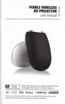
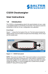
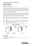
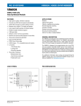
BASE-LINE WANDER & LINE CODING PREPARATION................................................................................. 28 what is base-line wander? ......................................................... 28 to do before the lab.................................................................... 29 what we will do ......................................................................... 29 EXPERIMENT ................................................................................... 30 overview .................................................................................... 30 observing base-line wander....................................................... 30 waveform snapshot display ......................................................................31 eye pattern display ...................................................................................32 noise margin loss: NRZ-L ......................................................... 32 noise margin loss: RZ-AMI....................................................... 34 other line codes.......................................................................... 36 TUTORIAL QUESTIONS ................................................................. 36 base-line wander & line coding copyright robert radzyner 2003 Vol D3-04, ch 4, ver 1.0 - 27 BASE-LINE WANDER & LINE CODING ACHIEVEMENTS: discover how base-line wander can be suppressed with line coding. PREREQUISITES: completion of the experiment entitled BER measurement in the noisy channel (Volume D2, Chapter 1) BASIC MODULES: 2 x ADDER, 2 x SEQUENCE GENERATOR ADVANCED MODULES: BASEBAND CHANNEL FILTERS, DECISION MAKER, ERROR COUNTING UTILITIES, LINE-CODE DECODER, LINE-CODE ENCODER, NOISE GENERATOR, WIDEBAND TRUE RMS METER SCOPE: availability of a digital or PC-based scope would be an advantage for eye pattern displays PREPARATION what is base-line wander? For an intuitive understanding of base-line wander we need go no further than the familiar lab scope. Everyone has at some stage needed to make use of the AC/DC switch on the lab scope. The AC setting is very useful to display a small AC signal superimposed on a large DC voltage, e.g. to observe milliVolt levels of residual AC ripple at the output of a DC power source. Provided the DC level stays constant we will have virtually total suppression of the DC component, after the initial connection transient settles. Let’s remain with this example, and suppose that we are observing the ripple in the presence of large loads switched on and off at frequent intervals, every few seconds, say. This will cause the DC level of the scope display to jump momentarily before settling back to its “base-line”. If the AC coupling time constant is large (order of seconds, say), return to the base-line will be slow. So, what has this to do with digital communication? Let’s look at data communications over telephone networks for example - these circuits are ACcoupled. Consider the transmission of a stream of random binary data. Suppose we format the binary symbols using a Bipolar-Return-to-Zero (BIP-RZ) line-code. We assume that in the long term the symbols are equiprobable. However, it’s not unreasonable to expect that over a given time interval, there will be some transient imbalance in the occurrence of the two symbols. Thus, over that interval the average voltage will not be zero, i.e. a DC component will be present. Since the data is random, the average voltage over a given 28 - Vol D3-04, ch 4, ver 1.0 base-line wander & line coding observation interval will tend to vary with time, hence causing the base-line to drift randomly. Let’s consider what happens at the detection circuit: the base-line of the symbols is wandering up and down relative to the fixed decision threshold (in this example, the threshold would be zero). Clearly, this will upset the proper operation of the decision process and lead to unsatisfactory performance – thus, BIP-RZ is not a good choice of line-code when operating over an AC coupled channel. This lab demonstrates base-line wander and how line coding is used to prevent it. to do before the lab This lab involves BER measurements described in detail in the experiment entitled BER measurement in the noisy channel 1. A brief review of this work will save time getting your set-up working. what we will do The experiment begins with an examination of scope displays showing base-line wander resulting from the use of unsuitable line codes. Next, a line-code that suppresses the accumulation of DC is used, and the improved waveform is compared with the first case. The work is completed by measuring bit error rate (BER) in the presence of noise. The performance degradation caused by base-line wander is assessed as a noise margin loss, i.e. we compare the SNR’s corresponding to a given BER in the presence and absence of base-line wander. SEQUENCE GENERATOR PRBS sync LINE CODE ENCODER reset bit clk AC or DC coupled 2.083 kHz DETECTOR Bandlimited Baseband Channel LINE CODE DECODER CLOCKED ERROR COUNT X-OR gate NOISE retimed bit clock SEQUENCE GENERATOR MASTER CLOCK 8.333 kHz make and break for alignment stolen bit clock TRANSMITTER CHANNEL RECEIVER PRBS sync reset bit clk INSTRUMENTATION Figure 1: block diagram of experiment 1 Volume D2, Chapter 1, base-line wander & line coding Vol D3-04, ch 4, ver 1.0 - 29 EXPERIMENT overview The experiment has been arranged in two parts. The first part involves observations of waveforms and eye patterns only, and can be completed quickly, not requiring the BER instrumentation set-up. The Bessel filter is used for band-limiting as it generates a particularly nice eye pattern with almost no intersymbol interference2 (ISI). In the second part we assess the degradation caused by base-line wander in the presence of noise. The procedure consists of measuring SNR’s for the various situations to be compared. We shall set the noise level to generate a given BER (40 per 100,000) and measure the corresponding SNR for each case. As often happens in engineering, solutions are not free of cost, and you will find the solution explored here is no exception! Some special care is required with the BER measurement set-up. It’s important to bear in mind that the DECISION MAKER requires appropriate amplitude levels for correct operation, especially for three level formats like RZ-AMI. These issues are discussed in detail in the User Manual, and in the previously mentioned experiment entitled BER measurement in the noisy channel. We use a symbol rate of 2083 per second as this is the best frequency for the monostable circuit in the DECISION MAKER for detecting half rate line codes such as RZ-AMI. A spin-off is that the clock is obtained from MASTER SIGNALS. observing base-line wander In this section we confine our attention to sequence waveforms. Noise or error rate measurements are not required at this stage. So, in order to get started quickly we connect the model up to the filter module only. The additional modules will be set up as required later. Note that the filter represents the combined effect of various filters in the transmitter, the channel and the receiver. d a ta in d a ta o u t Z- MO D re-tim e d b it c lo ck DC V ? s to le n b it c lo c k Figure 2: the model 2 The Bessel filter generates an ISI free eye pattern with RZ-AMI line coding for a pulse rate of 2083 per second, as used in this lab. The eye pattern with NRZ-L may show a small level of ISI at this pulse rate. This ISI can be eliminated by using BIP-RZ instead of NRZ-L at the filter input, and interpreting the resulting output as NRZ-L at the DECISION MAKER and LINE-CODE DECODER. 30 - Vol D3-04, ch 4, ver 1.0 base-line wander & line coding waveform snapshot display T1 before inserting the SEQUENCE GENERATOR select a short sequence (onboard DIP switch with both toggles UP). T2 patch up the model of Figure 2 up to the BASEBAND CHANNEL FILTERS (reminder: clock frequency division by four in the LINE-CODE ENCODER). T3 select the BESSEL FILTER from the BASEBAND CHANNEL FILTERS (front panel switch to channel 3), and DC on the other front panel switch. T4 choose the NRZ-L output on the LINE-CODE ENCODER. T5 synchronize the oscilloscope to the SYNCH output from the SEQUENCE GENERATOR, and observe a snap shot of the sequence from the BASEBAND CHANNEL FILTERS output (Figure 3a). Note the absence of base-line wander. Figure 3: (a) NRZ-L snapshot and (b) eye pattern (DC-coupled) Figure 4: (a) NRZ-L snapshot and (b) eye pattern (AC-coupled) T6 toggle the front panel switch of the BASEBAND CHANNEL FILTERS to the AC position. Observe the base-line wander(Figure 4a.). Record your observations. base-line wander & line coding Vol D3-04, ch 4, ver 1.0 - 31 Figure 5: (a) RZ-AMI snapshot and (b) eye pattern (AC-coupled) T7 repeat tasks T5 and T6 with the RZ-AMI output of the LINE-CODE ENCODER. Note the absence of base-line wander when using AC coupling. Examine and record the appearance of the waveform at the input and output of the filter (refer Figure 5). Note that the encoded waveform requires three amplitude levels. Consult the TIMS reference manual to confirm the encoding formula and explain how this scheme provides immunity against base-line wander. eye pattern display T8 re-set the SEQUENCE GENERATOR module to a long sequence (both toggles of the on-board DIP switch DOWN). Synchronize the oscilloscope to the clock of the SEQUENCE GENERATOR, and again observe the output of the BASEBAND CHANNEL FILTERS. Compare and record the appearance of the eye pattern with DC and AC coupling respectively for each of the two line codes used in T5 – T7 (Figures 3(b) and 4(b)). Observe the manifestation of base-line wander with NRZ-L. As in Task T7, note the presence of three levels in the case of the RZ-AMI line-code, and the absence of base-line wander. noise margin loss loss:: NRZ-L We proceed now to set up for the BER and SNR measurements, firstly with NRZ-L line coding. We shall start with the filters module in the DC-coupled mode. Although the use of RZ-AMI line coding suppresses base-line wander, we will also carry out measurements with this format to compare the performance relative to DCcoupled NRZ-L. T9 before inserting the DECISION MAKER set the on-board rotary switch SW1 to NRZ-L, and the on-board switch SW2 to INT. We return to waveform snap shot displays for the preliminary setting up of the BER measurement instrumentation. 32 - Vol D3-04, ch 4, ver 1.0 base-line wander & line coding T10 patch up the remainder of the model of Figure 2, i.e. the NOISE GENERATOR3, the DECISION MAKER, the LINE-CODE DECODER and the BER instrumentation. Choose the NRZ-L line code on both the LINE-CODE ENCODER and LINE-CODE DECODER modules. Set both SEQUENCE GENERATOR modules to a short sequence (both toggles of the on-board DIP switch UP). Synchronize the scope to the SYNCH output from the SEQUENCE GENERATOR, for displaying sequence waveform snap shots. Check that DC-coupling has been selected (front panel toggle switch on the filters module). T11 set the signal level at the DECISION MAKER input to (approx) 2 V p-p. Confirm that base-line wander is not occurring. T12 with noise absent, using the DECISION POINT front panel adjustment, guided by the bright spot on the eye pattern, adjust the position of the decision instants to occur at the peaks of the signal pulses. (refer to the Advanced Modules User Manual)). T13 observe the outputs of the DECISION MAKER and LINE-CODE DECODER, and verify that the transmitted sequence has been correctly regenerated. Note the time delay between the transmitted and regenerated sequences. T14 using the procedure described in the Experiment in Vol. D2, Chapter 1, entitled BER measurement in the noisy channel confirm that the second SEQUENCE GENERATOR is properly aligned4, and that the error count is zero5 at the X-OR output in the ERROR COUNTING UTILITIES. We return now to eye patterns for fine tuning, and to measure the eye opening. T15 re-set the SEQUENCE GENERATOR modules to a long sequence (both toggles of the on-board DIP switch DOWN). Synchronize the oscilloscope to the clock of the SEQUENCE GENERATOR, and again observe the input of the DECISION MAKER (without noise at this stage). Check the DC offset. For this experiment there is no need for adjustment if the offset is in the order of 30 mV or less. Verify that the decision points are aligned with the position of maximum eye opening – fine tune if needed. Carefully measure and record the peak-to-peak voltage of the inner envelope of the eye pattern at its maximum (the “eye opening”). We are now ready to proceed with BER measurements. 3 In a representative model the bandwidth of the noise would be limited to the bandwidth of the channel. To simplify the setting up we insert the wideband noise from the NOISE GENERATOR after the filter module. This does not affect the validity of our measurements since the error generation mechanism remains unaltered. 4 The alignment procedure should be carried out with snap shot displays. If you experience problems getting the second SEQUENCE GENERATOR to lock, the problem may be an inversion of the sequence ahead of the DECISION MAKER. 5 Reminder: the number of errors is the counter reading minus 1. base-line wander & line coding Vol D3-04, ch 4, ver 1.0 - 33 T16 gradually increase the noise level until you begin to register errors (if needed, refer to the Experiment in Vol. D2, Chapter 1, entitled BER measurement in the noisy channel for the details of the procedure). Set the noise level to obtain a BER near 40 in 100,000. Using the WIDEBAND TRUE RMS METER measure and record the RMS noise voltage at the input of the DECISION MAKER (temporarily disconnect the message to do this). T17 again using the WIDEBAND TRUE RMS METER measure and record the signal voltage at the input of the DECISION MAKER (with noise disconnected). Calculate and record the SNR in dB. It’s worth noting at this point that theoretical estimation of BER requires the signal amplitude at the decision instants, not the overall RMS amplitude. As set up, this is the signal amplitude at the point of maximum eye opening. You have already obtained this quantity when you measured the peak-to-peak eye opening. So, calculate a second SNR based on this measurement (don’t forget to divide the p-p value by two), and compare it with the first (using the same RMS noise measurement in both cases). Can you account for the difference (if any)? T18 repeat T16 with base-line wander present (toggle the front panel switch of the BASEBAND CHANNEL FILTERS to the AC position). Carefully adjust the noise level to obtain the same BER as closely as manageable (repeat the BER count a few times if needed). Record the results as in T16, and note the difference in SNR for the two cases (expressed in dB). This SNR increase is needed to prevent degradation of the BER in the presence of base-line wander. It represents the noise margin loss caused by the base-line wander. T19 with noise disconnected, measure the eye opening with base-line wander, as in task T15. Note that although the focus of the eye pattern nodes is poor due to the random base-line variations, there is nevertheless a well defined inner envelope (see Figure 5(b)) – the eye opening is the maximum p-p amplitude of this envelope. Compare this with the result obtained in the absence of base-line wander. Express the ratio of the two eye-opening measurements in dB. Compare this ratio with the noise margin loss obtained in T18, and comment on the outcome. noise margin loss loss:: RZ-AMI Next, we examine SNR/BER performance with RZ-AMI line coding. It’s important to recognize that although base-line wander does not occur, there is nevertheless a penalty associated with the use of this line code – a higher SNR is required for a given BER than with DC-coupled NRZ-L, or comparable code. This because the encoded (binary) message requires three levels (known as “pseudo-ternary” since only two information symbols are represented). 34 - Vol D3-04, ch 4, ver 1.0 base-line wander & line coding T20 in the DECISION MAKER, change the on-board rotary switch SW1 to RZ-AMI. Note that we briefly return to waveform snap shot displays to monitor the sequence alignment procedure of the BER measurement instrumentation. T21 choose the RZ-AMI line code on both the LINE-CODE ENCODER and LINECODE DECODER modules. Re-set both SEQUENCE GENERATOR modules to a short sequence (both toggles of the on-board DIP switch UP). Synchronize the scope to the SYNCH output from the SEQUENCE GENERATOR, for displaying sequence waveform snap shots. Check that DC-coupling has been selected (filters module front panel switch). Adjust the signal level at the DECISION MAKER input to 4 V p-p (NB was 2 V p-p with NRZ-L). T22 with noise absent, adjust the position of the decision instants to occur at the peaks of the signal pulses. T23 observe the outputs of the DECISION MAKER and LINE-CODE DECODER, and verify that the transmitted sequence has been correctly regenerated (note the time delay). T24 again using the procedure in Task T14 confirm that the second SEQUENCE GENERATOR is properly aligned, and that no errors are generated. We now return to eye patterns. T25 re-set the SEQUENCE GENERATOR modules to a long sequence (both toggles of the on-board DIP switch DOWN). Synchronize the scope to the clock of the SEQUENCE GENERATOR, and again observe the input of the DECISION MAKER (without noise at this stage). Check the DC offset (no need for adjustment if the offset is in the order of 30 mV or less). Verify that the decision points are aligned with the position of maximum eye opening – fine tune if needed. T26 note that the eye pattern has three levels, with two mirror-image inner envelopes, reflected about the zero axis. Carefully measure and record the peak-to-peak voltage for each envelope at the maxima. T27 switch to AC coupling to again confirm that the eye pattern is unchanged, i.e. there is no significant base-line wander. We are now ready to proceed with BER measurements. T28 as before, gradually increase the noise level until you begin to register errors. Set the noise level to obtain a BER near 40 in 100,000. Using the WIDEBAND TRUE RMS METER measure and record the RMS noise voltage at the input of the DECISION MAKER (temporarily disconnect the message for this task). base-line wander & line coding Vol D3-04, ch 4, ver 1.0 - 35 T29 again using the WIDEBAND TRUE RMS METER measure and record the signal RMS amplitude at the input of the DECISION MAKER (with noise disconnected). Calculate and record the SNR in dB. This SNR will be noticeably greater than the corresponding SNR with NRZ-L. It’s interesting to also compare with the SNR obtained when base-line wander is present. Is the SNR penalty incurred in using RZ-AMI worth the benefit? In dealing with this issue, consider whether the amplitude of base-line wander generated with our pseudo-random test sequence is representative of the levels that might be encountered in real life systems. To help you consider this question you could briefly examine the eye opening when AC-coupled NRZ_L is generated with sequences of other lengths. other line codes There is one other line code available in the LINE-CODING module set that provides suppression of base-line wander. You will be able to identify this line-code quite quickly with the techniques used above. This code has at least one advantage over RZ-AMI – it is not pseudoternary. Examine the structure of each of the other line-codes to spot the attribute that determines whether base-line wander will be suppressed. An important issue that has not been considered is bandwidth. Some of the line codes behave like non-linear modulation and produce a broadening and/or shifting of the spectrum. It’s essential to keep this in mind when selecting line codes to deal with base-line wander. If you have access to a spectrum analyser, you will find it worthwhile to obtain and compare the spectra of the coded waveforms. TUTORIAL QUESTIONS Q1 Discover one advantage of BiØ-L (Manchester) line coding over RZ-AMI as a solution for base-line wander. Q2 (a) Long sequences of the same symbol may be undesirable in some circumstances, such as a long string of zeros. Unlike RZ-AMI, BiØ-L line coding eradicates the occurrence of sustained “silence”. However this is generally insufficient, as the sending of a single frequency also may destabilize an adaptive equalizer. Find out how this problem is managed in real life applications. (b) Find out how modified RZ-AMI codes have been devised to deal with the occurrence of long strings of zeros. Q3 Line codes with a mandatory transition within the symbol such as BiØ-L tend to require a generous supply of a certain system resource. Which resource is this? However, there is a very useful spin off. What is that? Q4 Devise a simple encoder and decoder for RZ-AMI. 36 - Vol D3-04, ch 4, ver 1.0 base-line wander & line coding Q5 Find out the meaning of the term “coding factor” in the context of non-linear line codes. Look up the coding factor for RZ-AMI (J.A. Betts, "Signal Processing, Modulation and Noise", The English Universities Press, 1970. see Appendix III) Q6 Show why the measurement of noise margin loss is relatively insensitive to small DC offsets at the input of the detector. Assume the amplitude distribution of the noise is normal (gaussian). Q7 The term “code violation” is used to describe the occurrence of an anomalous combination of symbols at the detector output. Give an example that could occur with RZ-AMI, and indicate how this could be exploited usefully in the decoder. base-line wander & line coding Vol D3-04, ch 4, ver 1.0 - 37 38 - Vol D3-04, ch 4, ver 1.0 base-line wander & line coding