1
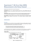
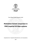
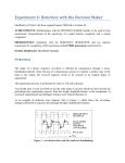
Experiment 3: Line Coding
Modified by Dr Peter Vial from EMONA original laboratory March 2011
ACHIEVEMENTS: familiarity with the properties of the LINE-CODE ENCODER and LINE-CODE DECODER
modules, and the codes they generate.
PREREQUISITES: an appreciation of the purpose behind line coding.
EXTRA MODULES: LINE-CODE ENCODER and LINE-CODE DECODER
PREPARATION
This ‘experiment’ is tutorial in nature, and serves to introduce two new modules.
In your course work you should have covered the topic of line coding at whatever level is appropriate for you. TIMS
has a pair of modules, one of which can perform a number of line code transformations on a binary TTL sequence.
The other performs decoding.
Why line coding?
There are many reasons for using line coding. Each of the line codes you will be examining offers one or more of
the following advantages:
•
spectrum shaping and relocation without modulation or filtering. This is important in telephone line
applications, for example, where the transfer characteristic has heavy attenuation below 300 Hz.
•
bit clock recovery can be simplified.
•
DC component can be eliminated; this allows AC (capacitor or transformer) coupling between stages (as in
telephone lines). Can control baseline wander (baseline wander shifts the position of the signal waveform
relative to the detector threshold and leads to severe erosion of noise margin).
•
error detection capabilities.
•
bandwidth usage; the possibility of transmitting at a higher rate than other schemes over the same
bandwidth.
At the very least the LINE-CODE ENCODER serves as an interface between the TTL level signals of the
transmitter and those of the analog channel. Likewise, the LINE-CODE DECODER serves as an interface between
the analog signals of the channel and the TTL level signals required by the digital receiver.
The modules
The two new modules to be introduced are the LINE-CODE ENCODER and the LINE-CODE DECODER.
You will not be concerned with how the coding and decoding is performed.
You should examine the waveforms, using the original TTL sequence as a reference.
In a digital transmission system line encoding is the final digital processing performed on the signal before it is
connected to the analog channel, although there may be simultaneous bandlimiting and wave shaping.
Thus in TIMS the LINE-CODE ENCODER accepts a TTL input, and the output is suitable for transmission via an
analog channel.
At the channel output is a signal at the TIMS ANALOG REFERENCE LEVEL, or less. It could be corrupted by
noise. Here it is re-generated by a detector. The TIMS detector is the DECISION MAKER module (already
examined in the experiment entitled Detection with the DECISION MAKER in this Volume). Finally the TIMS
LINE-CODE DECODER module accepts the output from the DECISION MAKER and decodes it back to the
binary TTL format.
Preceding the line code encoder may be a source encoder with a matching decoder at the receiver. These are
included in the block diagram of Figure 1, which is of a typical baseband digital transmission system. It shows the
disposition of the LINECODE ENCODER and LINE-CODE DECODER. All bandlimiting is shown concentrated in
the channel itself, but could be distributed between the transmitter, channel, and receiver.
The LINE-CODE ENCODER serves as a source of the system bit clock. It is driven by a master clock at 8.333 kHz
(from the TIMS MASTER SIGNALS module). It divides this by a factor of four, in order to derive some necessary
internal timing signals at a rate of 2.083 kHz. This then becomes a convenient source of a 2.083 kHz TTL signal for
use as the system bit clock.
Because the LINE-CODE DECODER has some processing to do, it introduces a time delay. To allow for this, it
provides a re-timed clock if required by any further digital processing circuits (eg, for decoding, or error counting
modules).
Terminology
•
•
The word mark, and its converse space, often appear in a description of a binary waveform. This is an
historical reference to the mark and space of the telegraphist. In modern day digital terminology these have
become HI and LO, or ‘1’ and ‘0’, as appropriate.
unipolar signalling: where a ‘1’ is represented with a finite voltage V volts, and a ‘0’ with zero voltage.
This seems to be a generally agreed-to definition.
•
those who treat polar and bipolar as identical define these as signaling where a ‘1’ is sent as +V, and ‘0’ as
-V. They append AMI when referring to three-level signals which use +V and -V alternately for a ‘1’, and
zero for ‘0’ (an alternative name is pseudoternary).
You will see the above usage in the TIMS Advanced Modules User Manual, as well as in this text.
However, others make a distinction. Thus:
•
•
•
•
•
polar signalling: where a ‘1’ is represented with a finite voltage +V volts, and a ‘0’ with -V volts.
bipolar signalling: where a ‘1’ is represented alternately by +V and -V, and a ‘0’ by zero voltage.
the term ‘RZ’ is an abbreviation of ‘return to zero’. This implies that the particular waveform will return to
zero for a finite part of each data ‘1’ (typically half the interval). The term ‘NRZ’ is an abbreviation for
‘non-return to zero’, and this waveform will not return to zero during the bit interval representing a
data ‘1’.
the use of ‘L’ and ‘M’ would seem to be somewhat illogical (or inconsistent) with each other. For example,
see how your text book justifies the use of the ‘L’ and the ‘M’ in NRZ-L and NRZ-M.
two sinusoids are said to be antipodal if they are 1800 out of phase.
available line codes
For a TTL input signal the following output formats are available from the LINECODE ENCODER.
NRZ-L
Non return to zero - level (bipolar): this is a simple scale and level shift of the input TTL waveform.
NRZ-M
Non return to zero - mark (bipolar): there is a transition at the beginning of each ‘1’, and no change for a ‘0’. The
‘M’ refers to ‘inversion on mark’. This is a differential code. The decoder will give the correct output independently
of the polarity of the input.
UNI-RZ
Uni-polar - return to zero (uni-polar): there is a half-width output pulse if the input is a ‘1’; no output if the input is
a ‘0’. This waveform has a significant DC component.
BIP-RZ
Bipolar return to zero (3-level): there is a half-width +ve output pulse if the input is a ‘1’; or a half-width -ve output
pulse if the input is a ‘0’. There is a return-to-zero for the second half of each bit period.
RZ-AMI
Return to zero - alternate mark inversion (3-level): there is a half-width output pulse if the input is a ‘1’; no output if
the input is a ‘0’. This would be the same as UNI-RZ. But, in addition, there is a polarity inversion of every alternate
output pulse.
Biφ-L
Biphase - level (Manchester): bipolar ±V volts. For each input ‘1’ there is a transition from +V to -V in the middle
of the bit-period. For each input ‘0’ there is a transition from -V to +V in the middle of the bit period.
DICODE-NRZ
Di-code non-return to zero (3-level): for each transition of the input there is an output pulse, of opposite polarity
from the preceding pulse. For no transition between input pulses there is no output.
The codes offered by the line-code encoder are illustrated in Figure 2 below. These have been copied from the
Advanced Module Users Manual, where more detail is provided.
The output waveforms, apart from being encoded, have all had their amplitudes adjusted to suit a TIMS analog
channel (not explicitly shown in Figure 2). When connected to the input of the LINE-CODE DECODER these
waveforms are de-coded back to the original TTL sequence.
band limiting
No matter what the line code in use, it is not uncommon to bandlimit these waveforms before they are sent to line, or
used to modulate a carrier. As soon as bandlimiting is invoked individual pulses will spread out (in the time domain)
and interfere with adjacent pulses. This raises the issue of inter-symbol interference (ISI).
A study of ISI is outside the intended scope of this text, but it cannot be ignored in practice. Bandlimiting (by pulse
shaping) can be effected and ISI controlled by appropriate filter design (called channel equalisers).
An alternative approach, duobinary encoding, was invented by Lender [1]. As an exercise outside the laboratory you
might go to the IEEE Explore electronic database available on the University of Wollongong Library website and
briefly read this reference. You do not need to do this to complete this laboratory, however.
duobinary encoding
A duobinary encoder (and decoder) is included in the line code modules. Duobinary encoding is also called
correlative coding, or partial response signalling. The precoded duobinary encoding model implemented in the
LINE-CODE ENCODER module is described in the TIMS Advanced Modules User Manual (see website).
Experiment
Figure 3 shows a simplified model of Figure 1. There is no source encoding or decoding, no baseband channel, and
no detection. For the purpose of the experiment this is sufficient to confirm the operation of the line code modules.
When a particular code has been set up, and the message successfully decoded without error, the BUFFER should be
included in the transmission path. By patching it in or out it will introduce a polarity change in the channel.
If there is no change to the message output, then the
code in use is insensitive to polarity reversals.
Note that the LINE-CODE DECODER requires, for successful decoding, an input signal of amplitude near the TIMS
(±2 volt peak-peak). In normal applications this is assured, since it will obtain its input
from the DECISION MAKER.
ANALOG REFERENCE LEVEL
Procedure
There are no step-by-step Tasks for you to perform. Instead, it is left to you to ensure that (in the approximate order
indicated):
1. You read the TIMS Datasheets for more details of the LINE-CODE ENCODER and LINE-CODE DECODER
modules than is included here (see website).
2. You select a short sequence from the transmitter message source.
3. At least initially you synchronize the oscilloscope to show a snapshot of the transmitter sequence. This is done by
triggering the oscilloscope on the SYNC output of the SEQUENCE GENERATOR. In experiment 5 we will look at
snapshots and eye diagrams (if you want to read ahead).
4. Examine each code in turn from the encoder, confirming the transformation from TTL is as expected, using the
information available in the TIMS Datasheets. You may also like to do some research and confirm that these
techniques are the same or similar to those in your text books or references for this subject. To do this, setup one of
the buffer amplifiers to have a gain of -1. Check each coding scheme without a buffer amplifier and with a buffer
amplifier and comment on which coding schemes are un-affected by the presence of an inversion (180 degree phase
shift) in the channel. Also comment on what needs to be done to the received TTL signal to recover the effect of
inversion (eg do we need to logically invert the received TTL signal?).
5. Of significant interest would be an examination of the power spectra of each of the coded signals. For this
laboratory take the power spectra of the first two coding schemes (NRZ-L and NRZ-M), sketch these and
compare the two plots. In particular note the ‘envelope’ of the spectra and the spacing between discrete components
(which should be related to the fundamental frequency of your line code signals, ie the clock frequency).
resetting
Resetting of the LINE-CODE ENCODER and the LINE-CODE DECODER after the master clock is connected, or
after any clock interruption, is strictly not necessary for all codes. But it is easier to do it for all codes rather than
remember for which codes it is essential. This means you have to press the reset button on the encoder followed by
the reset button on the decoder. You can also turn the TIMS off and then on again which will then mean that this
will be required. When doing that put the oscilloscope on the output of the SEQUENCE GENERATOR and the
output of the LINE-CODE DECODER and watch the lack of an output turn into a related signal trace (there may be
a phase delay).
For more details refer to the TIMS Advanced Modules User Manual.
Tutorial Questions
Q1 why introduce the complications of line encoding in a digital transmission system?
Q2 apart from the inevitable delay introduced by the analog filter, did you notice any other delays in the system?
You may need this information when debugging later experiments.
Q3 an important function of many line encoders is the elimination of the DC component. When is this desirable?
Bibliography
[1] Lender, A. “Thue Duobinary Technique for High Speed Data Transmission”, IEEE Trans. Comm. Electron, vol
82, pp. 214-218, May 1963