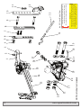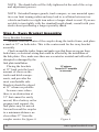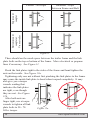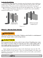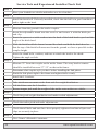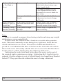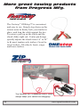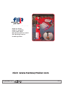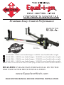
1
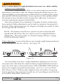
OWNER’S manual
Premium Sway Control Performance
MADE IN THE
U.S.A.
Hitch Ball
Not Included
A
W
2 0 1 2
A R
D
N
W I N
E
R
90-00-0600 - 600 lb. max loaded tongue / 6,000 lb. max loaded trailer weight
90-00-1000 - 1,000 lb. max loaded tongue / 10,000 lb. max loaded trailer weight
90-00-1200 - 1,200 lb. max loaded tongue / 12,000 lb. max loaded trailer weight
90-00-1400 - 1,400 lb. max loaded tongue / 14,000 lb. max loaded trailer weight
** Your model # can be found on the stickers on either spring arm. Make a note of it here for future reference **
dealers: please pass this manual on to the
end user after hitch installation.
www.EqualizerHitch.com
READ entire manual before starting installation
Attention Hitch Owner:
REPLACEMENT
A replacement copy of this manual may be downloaded from
www.EqualizerHitch.com or by calling 1-800-478-5578.
KEEP THIS MANUAL
Keep this manual in a safe place as a reference for regular adjustment and
maintenance.
FURTHER ASSISTANCE
If you do not understand any part of this manual contact a qualified
Equal‑i‑zer® hitch dealer in your area or Progress Mfg. Inc. customer service
at 1-800-478-5578 or by visiting www.EqualizerHitch.com.
Congratulations on your purchase of The Original
Equal-i-zer® Sway Control Hitch.
Thank You for your purchase and welcome to
the Equal-i-zer® hitch family. We appreciate your
business and constantly strive to exceed your
expectations.
Read this owner’s manual thoroughly to become
familiar with proper set-up and maintenance
procedures to ensure that your Equal-i-zer® hitch
will give you maximum performance and years of
service.
Happy Towing,
The Employees of Progress Mfg. Inc.
2
www.equalizerhitch.com
Table of Contents
Page
Parts Breakdown . . . . . . . . . . . . . . . . . . . . . . . . . . . . 4
Important Safety Information . . . . . . . . . . . . . . . . . . . . . 6
Important Hitch Information . . . . . . . . . . . . . . . . . . . . . . 7
Step 1: Setup Location . . . . . . . . . . . . . . . . . . . . . . . . 9
Step 2: Install the Hitch Ball . . . . . . . . . . . . . . . . . . . . . 9
Step 3: Attach Hitch Head to Shank . . . . . . . . . . . . . . . . .10
Step 4: Sway Bracket Assembly Set Up . . . . . . . . . . . . . . .12
Step 5: Spring Arm Setup . . . . . . . . . . . . . . . . . . . . . . 15
Step 6: Weight Distribution Setup . . . . . . . . . . . . . . . . . .16
Step 7: Weight Distribution Adjustments . . . . . . . . . . . . . . .18
Step 8: Trailer Pitch Adjustments . . . . . . . . . . . . . . . . . . 21
Step 9: Final Tightening . . . . . . . . . . . . . . . . . . . . . . . 22
Step 10: Regular Maintenance . . . . . . . . . . . . . . . . . . . . 23
Service Tech Check List . . . . . . . . . . . . . . . . . . . . . . . 24
Appendix A: Troubleshooting Guide . . . . . . . . . . . . . . . . .25
Customer Service . . . . . . . . . . . . . . . . . . . . . . . . . . .27
Appendix B: Weight Distribution Adjustments . . . . . . . . . . . .27
Warranty . . . . . . . . . . . . . . . . . . . . . . . . . . . . . . . .29
TOOLS NEEDED FOR INSTALLATION
The following tools will allow you to install the hitch properly.
1-1/8” Box-end wrench (Shank Bolts)
1-1/8” Socket wrench (Shank Bolts)
3/4” Box-end wrench (Link Plates and L-brackets)
3/4” Socket wrench (Link Plates and L-brackets)
5/8” Socket or box-end wrench (Angle Set Bolt)
Measuring tape
Pencil
Torque wrench capable of 320 Ft-lbs of torque. (Shank Bolts)
Torque wrench capable of 75 Ft-lbs of torque. (Sway Bracket Assembly)
Recommended tools for installing the Hitch Ball:
1-7/8” Thin-wall socket (available from Progress Mfg. Inc.)
Torque Wrench capable of 430 Ft-lbs of torque (or higher if hitch
ball manufacturer specifies).
A product of
3
4
www.equalizerhitch.com
21
17
20
NOTE: Hitch ball not included.
22
23
24
19
25
18 17
26 27
1
2
16
3
15
4
5 6
14
7
9
13
10
12
11
WARNING
MAKE SURE THE ANGLE SET BOLT (UNDER HITCH HEAD)
AND SHANK BOLTS ARE PROPERLY TIGHTENED BEFORE
EACH DRIVE. CHECK ALL NUTS AND BOLTS FOR PROPER
TIGHTNESS AND FATIGUE AS A COMMON SAFETY PRACTICE.
FAILURE TO DO SO WILL VOID YOUR WARRANTY
For longer hitch life, keep Equal-i-zer®’s
rotational friction surfaces lubricated.
Keep socket bolt tight. (approx. 45 ft. lbs.)
Item # 29 - Socket Warning Sticker
8
A product of
5
90-02-4100
90-04-9224
90-03-9220
90-04-9228
90-04-9290
90-02-5200
90-04-9281
90-02-5370
90-04-9270
90-02-5150
90-04-9286
90-03-9230
90-03-6200
90-03-6100
90-04-9131
90-03-9212
90-04-9115
90-04-9216
1
2
3
4
5
6
7
8
9
10
11
12
13
14
15
16
17
18
IT IS THE DRIVER’S RESPONSIBILITY TO MAKE THE NECESSARY
ADJUSTMENTS TO THEIR DRIVING HABITS, TRAILER, TOW VEHICLE,
AND TOWING EQUIPMENT TO AVOID TRAILER SWAY. TRAILER
SWAY HAS MANY CAUSES, INCLUDING: IMPROPER TRAILER LOADING,
TIRE PRESSURE, DRIVING TECHNIQUES, SPEED, PASSING VEHICLES,
WEATHER CONDITIONS, ROAD CONDITIONS, AND OTHERS. THERE
IS NO 100% QUALITATIVE MEASUREMENT OF TRAILER SWAY OR
SWAY CONTROL. USERS MUST EXERCISE CAUTION AT ALL TIMES
WHILE TOWING A TRAILER AND ABIDE BY ALL TRAFFIC LAWS.
IT IS THE OPERATORS RESPONSIBILITY TO READ AND
UNDERSTAND PRODUCT INSTRUCTIONS AND PROPER USE.
ATTENTION
Item# 28 - Spring Arm Warning Sticker
Part Number
Item #
1
1
1
4
4
2
4
2
4
2
4
2
1
1
2
2
4
2
Qty.
25
26
27
24
21
22
23*
BD064
BD104
BD124
BD144
BD035
90-04-9110
90-03-9105
90-03-9700
90-02-0600
90-02-1000
90-02-1200
90-02-1400
90-04-9120
90-04-9126
90-02-0699
90-02-1099
90-02-1299
90-02-1499
19
20
Part Number
Item #
Angle Set Bolt
600 / 6,000 lb. head
1,000 / 10,000 lb. head
1,200 / 12,000 lb. head
1,400 / 14,000 lb. head
3/4” Lock Washer
3/4” Nut
6,000 lb. Spring Arm
10,000 lb. Spring Arm
12,000 lb. Spring Arm
14,000 lb. Spring Arm
Arm Warning Stickers
6,000 lb. arm sticker
10,000 lb. arm sticker
12,000 lb. arm sticker
14,000 lb. arm sticker
Socket Warning Sticker
Spacer Washer
Spacer Rivet
Part Description
2
6
1
2
2
2
2
1
6
Qty.
™
www.equalizerhitch.com
Equal-i-zer® is a product of Progress Mfg. Inc.
For a copy of the hitch instructions call
Progress Mfg. Inc. at 1-800-478-5578 or visit:
V5 & SAE Tested
MADE IN THE USA
Model# 90-00-XXXX
Max. Tongue Weight ___ Lbs.
Max. Trailer Weight _____ Lbs.
* Each package contains two (2) spring arms. These arms are specifically
sized for your hitch head. Spring arms will not function with a hitch head of a
different rating.
SWAY CONTROL
4-POINT
Adjustable Shank
Hitch Pin Clip
Hitch Pin
1/2” Nut
1/2” Lock Washer
Inside Link Plate
1/2” x 1-1/2” Bolt
Outside Link Plate
1/2” x 3-1/2” Bolt
L-Bracket
Nylock Jam Nut
Snap L-Pin
Snap-up Handle
Snap-up Hook
3/4” x 5” Bolt
Socket Pin
3/4” Washer
Socket Pin Clip
Part Description
EQAS0308
Important Safety Information
Failure follow all safety warnings may result in severe injury or death.
WARNING
Read, understand, and follow all safety warnings, setup, use, and main‑
tenance instructions of your trailer, tow vehicle, and hitching equipment
before installing your hitch or towing your trailer.
WARNING
Never cut, weld, grind, bend, or modify hitch components in any way.
It is the drivers responsibility to adjust equipment and driving habits to
match towing conditions. The driver is responsible for their own safety
and the safety of passengers.
Never exceed the specified weight ratings for the trailer, tow vehicle,
hitch, hitch ball, or any other towing equipment.
No hitch setup guarantees that trailer sway will be altogether avoided.
Always load trailer correctly. Follow trailer and tow vehicle manufac‑
turers’ recommendations for placement and quantity of cargo.
Always tow with a minimum tongue weight of 10% of gross trailer weight.
Always use a hitch ball with a rating that equals or exceeds the trailer
Gross Vehicle Weight Rating (GVWR). Always use a hitch ball size that
correctly matches your trailer coupler size and make sure it is coupled
securely before towing.
Measuring weight distribution setup well does not ensure safe towing.
The operator is responsible for making necessary adjustments to the
hitch to optimize weight distribution and sway control. Each trip is
different, and the weight distribution setup and towing performance
should be evaluated by the operator and adjusted when necessary.
Never tow with your hitch adjusted incorrectly.
6
www.equalizerhitch.com
WARNING
Check all hardware before each trip. Do not tow your trailer until all
bolts and nuts have been checked for wear and fatigue, are properly
tightened, and all pins and clips are securely in place.
WARNING
Do not tow your trailer on rough roads. Do not tow your trailer through
profound ditches, dips, or swales. Excessive strain on the spring arms
and hitch head may cause hitch fatigue or failure.
If your dealer installed your hitch, make sure to verify that it is still ad‑
justed correctly after loading your trailer and tow vehicle for your trip.
Replace worn, faded, or unreadable warning stickers on the spring
arms and arm sockets.
Do not transfer hitch to a different tow vehicle or trailer without
re‑adjusting the hitch for proper weight distribution.
CAUTION
Do not loosen or remove any part of the hitch while the hitch is under load.
Use the tongue jack to take the tension off the spring arms before removing
L-pins.
CAUTION
Always secure tow vehicle and trailer with parking brake and wheel
chocks before setting up or adjusting hitch.
Important Hitch Information
Weight Distribution:
Weight distribution is the ability of a hitch to transfer some of the tongue
weight of the trailer from the rear axle of the tow vehicle to the front axle of
the tow vehicle, and backward to the trailer axles. Without weight distribution the tow vehicle “teeter-totters” on the rear axle of the tow vehicle, and
unweights the front axle. Proper weight distribution transfers weight back to
the front steering axle, forcing it back to the ground.
A product of
7
Proper weight distribution also adds performance to the Integrated Sway
Control™ feature of your Equal-i-zer® hitch. The Equal-i-zer hitch requires
a minimum tongue weight of at least 10% of gross trailer weight. This
tongue weight gets distributed, and helps generate the friction needed to
reduce trailer sway.
Sway Control:
Integrated Sway Control is a built-in, patent pending feature of your
Equal-i-zer hitch. Once the spring arms are tensioned, the sway control is in
force.
Integrated Sway Control works through the connection between your
spring arms and L-brackets, and between the sockets and hitch head. The
Equal-i-zer hitch takes advantage of the steel-on-steel friction generated at
these points to help reduce trailer sway.
This added friction makes it much more difficult for the trailer to sway
side-to-side while its being towed, as sometimes happens when you encounter a gust of wind, or passing semi. When set up well and properly adjusted
for your load, the Equal-i-zer can noticeably reduce sway.
Important Setup Information:
These instructions are a guideline to aid in setting up your hitch. Every
trailer and tow vehicle combination requires a different setup and adjustment because of factors like trailer weight and length, trailer loading, hitch
weight, and tow vehicle geometry and suspension. It is not likely that a good
setup for one vehicle combination will work well for another. If you change
tow vehicle and/or trailer, you should check the hitch setup for proper
weight distribution and adjust it when necessary.
You must use your best judgment to determine if changes to the setup
are required to ensure a safe and comfortable towing situation. There is no
all-inclusive formula for setting up or adjusting a hitch that will accommodate each combination of trailer and tow vehicle possible.
The setup may need to be changed slightly at times to accommodate
changes in your towing configuration, perhaps even during the same trip. For
example, a trailer that starts with full clean water and propane tanks, may tow
differently when that water becomes black and grey water, and the propane
tanks are empty. Or, a trailer loaded with gear for a long cross country trip
may tow differently than the same trailer loaded for a weekend getaway. The
driver must be conscious of these changes, and adjust the hitch accordingly.
8
www.equalizerhitch.com
Step 1 - Set up Location:
While installing or adjusting the hitch, the tow vehicle and trailer should
be loaded just as they will be while traveling. This includes full propane and
fresh water tanks, and any other cargo the tow vehicle (passengers & gear)
or trailer will carry, including ATVs for toy haulers. Tow vehicle “auto-level” systems should also be disabled or turned off temporarily.
Park the trailer and tow vehicle on level ground and in line with each
other. Chock and uncouple the trailer. Pull tow vehicle ahead about 5 feet to
allow working area and set the parking brake.
Step 2 - Install the Hitch Ball:
WARNING
WARNING
Never exceed the specified weight ratings for the trailer, tow vehicle,
hitch, hitch ball, or any other towing equipment.
NOTICE
Using a hitch ball with a shank longer than 2-3/8” may damage the
NOTICE
Equal-i-zer
hitch head and could void your warranty.
Install a properly-sized hitch ball (not included) onto the hitch head. Ball
diameter must match trailer coupler size.
Select a ball with a 1-1/4” diameter threaded shank no longer than
2-3/8”. Hitch balls with a longer shank may damage the hitch. If your
hitch ball has a smaller diameter shank you must use an appropriate bushing. Make sure that the ball has a weight rating equal to or greater than your
trailer’s gross vehicle weight rating (GVWR). Always use a lock washer
against the nut, unless otherwise specified by ball manufacturer. Torque nut
to ball manufacturer’s specifications.
Hitch balls require a 1-7/8” socket and a torque wrench capable of
approximately 430 Ft-lbs torque for installation. Your nearest Equal-i-zer
dealership will have the tools needed and will usually install the hitch ball
for a reasonable fee.
A product of
9
Step 3 - Attach Hitch Head to Shank:
Level the Trailer:
Measure to the ground at the FRONT and BACK of the trailer frame,
and adjust the trailer to be parallel to the ground (both FRONT and BACK
measurements should be the same).
With the trailer parallel to the ground, measure from the ground to the
top of the trailer coupler. The hitch ball should initially be placed as close to
this height as possible. See Figure 1.
??”
Trailer Coupler Height: __________ . Set hitch ball to this height.
Figure 1
Attach Head to Shank:
Insert the adjustable shank into the receiver on the tow vehicle and secure it with hitch pin and clip.
Insert the spacer rivet with washers into the back of the hitch head to
pre-load the angle of the hitch head. Start with 5 spacer washers for most
setups. If your actual tongue weight is higher than 90% of the hitch’s max
tongue weight rating (i.e. TW > 1,080 lb. on a 12K hitch), you may want to
start with 6 spacer washers. Some setups with lighter tongue weights may
only need 4 washers.
Slide the bolt channel around the shank and hold the hitch head so that
the top of the hitch ball measures from the ground as closely as possible to
the coupler height. This is generally a step that requires two people.
10
www.equalizerhitch.com
Observe where the top slot
in the bolt channel aligns with the holes
in the shank. See Figures 2a - 2b. If you
can see any part of the shank hole that is
lower than the bolt channel slot, drop the
head down to align these holes for the
initial setup. See Figure 2a.
If you cannot see the lower hole in
the shank, raise the hitch head so that
the top slot aligns with the shank hole
slightly above it, and use this hole for the
initial setup. See Figure 2b.
Figure 2a
Figure 2b
Figure 3
In some cases, the shank may need to be turned
upward, or a specialty length shank may be needed
so that the ball can be placed at the correct height.
See Figure 3.
Insert a 3/4” shank bolt with a flat washer
through the top slot in the bolt channel and
shank hole to hold the head at the correct
height. Slide the flat washer, split (lock) washer, then nut onto the other side of the bolt, and
finger tighten them. Then repeat this process
for the bottom shank bolt. See Figure 4.
Use a wrench to tighten the angle set bolt
until it comes into contact with the shank and lifts
the head to where the spacer rivet also comes into
solid contact with the shank. Tighten the angle set
bolt an additional 1/2 turn. The hitch head should
be angled down slightly. See Figure 5.
A product of
Figure 4
Figure 5
11
OTE: The shank bolts will be fully tightened at the end of the set up
N
and adjustment process.
OTE: Extended bumper guards, truck campers, or rear mounted spare
N
tires can limit turning radius and may lead to a collision between tow
vehicle and trailer in a tight turn unless a longer shank is used. If you are
not able to turn tightly with the standard length shank, consult with your
dealer about purchasing a longer specialty shank.
Step 4 - Sway Bracket Assembly:
Sway Bracket Location
Measure from the center of the coupler along the trailer frame, and place
a mark at 32” on both sides. This is the center mark for the sway bracket
assembly.
Check around the trailer frame and make sure that there are no gas lines,
brake lines, or electrical wiring that could be affected by the installation of
the link plates. If so, make sure these are re-routed or avoided and will not be
disrupted or damaged by the
link plate installation.
32” optimum.
Placing the brackets
Forward
to 27” acceptable
at 32” back puts the least
in some cases.
amount of stress on the
trailer and hitch components, and provides the
most comfortable ride.
Brackets should be placed
at 32” whenever possible.
In some cases where
there is an obstruction at
32” that cannot be easily
moved, like a battery rail or
propane tank support, the
link plates may be moved
forward toward the coupler
to a minimum distance no
closer than 27” from the
Figure 6
coupler center. See figure 6.
12
www.equalizerhitch.com
CAUTION
Do not use impact wrench to tighten link plate or L-bracket bolts.
CAUTION
Assemble Link Plates
Insert two 1/2” x 1-1/2” bolts through the outside
link plate from the back side. The head of the bolts
should fit completely inside the pocket on the back.
Insert one 1/2” x 3-1/2” bolt through the single hole
on the outside link plate, and the single hole on the
inside link plate. The head of the bolt should fit into
the pocket of the outside link plate.
Slide on a split washer, and then thread on the 1/2”
nut a few turns. See Figure 7.
Identify your coupler style. See Figure 8.
Top-Mount
Figure 7
Bottom-Mount
Figure 8
If your trailer has a top-mounted coupler, drop the
link plates over the top of the frame and insert the
bottom bolt through the hole closest to the bottom
of the trailer frame. Slide on a split washer, then
thread a 1/2” nut onto the bolt. See Figure 9.
Figure 10
A product of
Figure 9
If your trailer has a bottom-mounted coupler, is a
V-nose trailer, or has some other obstacle that makes
using the hitch difficult with the brackets mounted
in the standard position, install the link plates upside
down on your frame. Slide the assembly up from the
bottom. Hold the bolt up tight to the bottom of the
frame and thread the top bolt through the link plate
hole closest to the top of the trailer frame. Slide on a
split washer, then thread a 1/2” nut onto the bolt. See
Figure 10.
13
Incorrect - Gaps
Between Frame and Bolt
Bottom-mount
coupler or
V-nose trailer
Top-mount
coupler
Correct - No Gaps
Figure 11
There should not be much space between the trailer frame and the link
plate bolts on the top or bottom of the frame. Move electrical or propane
lines if necessary. See Figure 11.
Pinch the link plates tight to the sides of the frame and hand tighten the
nuts on the inside. See Figure 12a.
Tightening only one nut without first pinching the link plates to the frame
may cause the inside link plate to bend when torqued completely. It may
also give you a torque
wrench reading that
indicates the link plates
are tight, even though
they are not. See Figure
12b.
After both nuts are
finger tight, use a torque
wrench to tighten all link
plate bolts to 50 - 70
Figure 12a
Figure 12b
ft-lbs. torque.
14
www.equalizerhitch.com
L-bracket Installation
For the first setup, slide the L-brackets onto the link plate studs with the toe
facing away from the trailer. Leave 2 holes showing at the top above the studs
and two below. They may need to be adjusted up or down later to get good
weight distribution. Thread on the nylock nuts and tighten them. See Figure 13.
When weight distribution adjustment is complete these nuts should be
torqued to between 65 - 75 ft-lbs.
Top-mounted
coupler (fig. 8)
Bottom-mounted
coupler (fig. 8)
Figure 13
Step 5 - Spring Arm Setup:
WARNING
Never tow with loose socket bolts. Tighten socket bolts to a minimum of
45 Ft-lbs torque before each towing session.
WARNING
CAUTION
Do not pound directly on the sockets to move them. Pounding may cause
the sockets to crack or chip. Use only the lever force of the spring arm to
move tight sockets. Loosen the socket bolt if required. Re-tighten them
once the socket has been moved.
CAUTION
Insert spring arms into the sockets in the hitch head. Arms for the 12K
and 14K models are side specific. They are notched slightly off-center, and
should be inserted into the socket with the notch on the inside, and with the
label facing outward.
A product of
15
Insert the socket pin through the hole in the socket and spring arm, and
secure it with the socket pin clip. You may need to use the spring arm as
a lever to spread the sockets open, which will allow the spring arms to be
lifted and placed onto the L-bracket more easily.
Step 6 - Weight Distribution Setup:
Use the following guidelines to set up and adjust your Equal-i-zer hitch
for weight distribution. Good weight distribution is a critical component of
the Equal‑i‑zer hitch setup. A hitch that is set up poorly for weight distribution will not perform like one that is set up well. Every tow vehicle and
trailer combination will react differently to weight distribution.
To correctly set up weight distribution you must take 3 sets of measurements on your tow vehicle. First, measure without the trailer coupled.
Next, measure with the trailer coupled, but with no weight distribution.
Third, measure coupled with the weight distribution bars tensioned.
Start by measuring the distance from the ground to the wheel well directly above the front axle with the trailer uncoupled. See Figure 14. Record
this on Line A of the weight distribution setup table.
Measure from ground
to fender through the
center-line of the axle.
Figure 14
Rear
Front
Weight Distribution Setup Table
FRONT
Example
A
Tow vehicle loaded for trip but still uncoupled from trailer
28”
B
Tow vehicle coupled but NO weight distribution
30”
Calculate height halfway between A and B (A+B)÷2=
29”
C
16
Tow vehicle coupled with weight distribution engaged.
Should be at least halfway back to Line A. Higher
than this may still be under adjusted. Lower than Line A
is over adjusted. See Figure 19.
28”-29”
Good
__________
29”-30”
Need More
www.equalizerhitch.com
Back the tow vehicle to the trailer and lower the coupler onto the ball.
Lock the coupler and retract the tongue jack until it raises off the ground
about 1” so that the full tongue weight of the trailer is resting on the hitch.
Measure the tow vehicle height again exactly above the front axle, to the
same point that you measured to earlier when uncoupled. Record this on
Line B of the weight distribution setup table above.
With the tow vehicle still coupled to the trailer, use the tongue jack to
lift both vehicles until you can swing the spring arms into place over the Lbrackets. See Figure 15.
Figure 15
If you reach the top of the jack before the spring arms will swing into
position, you can use the Snap-up Lever to lift the spring arms up and onto
the L-brackets. Use the L-pins to secure the spring arms on the L-brackets.
See Figures 16-17.
Figure 16
With the spring arms resting on the
L-bracket and the trailer and tow vehicle
in line with each other, check to make sure
that there is a minimum of 3” from the end
of the spring arms to the center of the link
plates. See Figure 17. Move and re-tighten
the link plates if necessary.
A product of
Figure 17
3”
Figure 17
17
OTE: Refer to Appendix B “Weight Distribution Adjustments” on
N
page 27 for a more detailed description of factors that influence weight
distribution setup and adjustment.
With the trailer coupled and weight distribution engaged, re-measure the
front wheel well height exactly as done before in Step 1. Record this new
measurement on Line C of the weight distribution setup table on page 16.
Step 7 - Weight Distribution Adjustments:
WARNING
Weight distribution is only one of many things that influence sway. The
operator is responsible for making necessary adjustments to all contrib‑
uting factors in order to minimize sway.
WARNING
Good adjustment:
You have most likely achieved good weight distribution adjustment if your
measurement on Line C of the weight distribution setup table shows that
front wheel well measurement is at least halfway back to the original uncoupled measurement. See Line C on Weight Distribution Setup Table and
Figure 19 below. It should never be lower than
Line A.
B coupled - no WD
C halfway back with WD
A uncoupled
needs
more
good
adjustment
See Weight Distribution
Setup Table on p. 16.
Figure 19
18
www.equalizerhitch.com
WARNING
Over or under adjusted weight distribution decreases tow vehicle stability.
Under or Over Adjustment:
If the hitch is transferring too little or too much weight you must make
adjustments to the hitch setup. For changes during the initial setup we recommend adding or removing spacer washers first to try and keep the spring
arms parallel with the trailer frame. In our experience, this can help reduce
the amount of noise the hitch makes during slow, tight turns. It also gives
you more adjustment options if needed later.
Once the maximum (8) or minimum (4) number of spacer washers has
been reached, further adjustments can be made by raising or lowering the Lbrackets. Minor adjustments later for changes in loading can usually be done
by moving only the L-brackets.
WARNING
NOTE: The distance from the tow vehicle rear axle to the hitch ball
significantly affects how the tow vehicle reacts to weight distribution
adjustments. The same washer or L-bracket change will have varying
results on different vehicles.
Under adjustment occurs when there is not enough weight being transferred
to the front axles of the tow vehicle. See Figure 20.
Figure 20
You most likely need more weight distribution adjustment if your measurements show that from the coupled without weight distribution measurement, the front wheel well measurement is STILL HIGHER THAN halfway
back to the original uncoupled measurement. See Line C on Front Wheel
Well Measure Chart. With an under adjusted setup your hitch is not giving
back as much steering control as it could, nor is it providing as much friction
as it could to help reduce trailer sway.
A product of
19
To correct under adjustment you must add more weight distribution
force to the hitch by adding spacer washers, or raising the L-brackets.
If this is the initial set up, use the tongue jack to unload the spring arms.
Remove the spring arms from the hitch head. Uncouple the trailer and pull
tow vehicle forward. Remove the hitch head and add a spacer washer. Repeat step 5 and 6 to re-adjust and check weight distribution.
If you have reached the maximum number of spacer washers, or if adjusting temporarily due to a change in vehicle loading, use the tongue jack to
unload the spring arms. Raise the L-brackets 1 hole. Move the spring arms
back over the L-brackets and retract the tongue jack. Re-measure the wheel
wells and check for proper weight distribution.
Repeat Steps 5 and 6 until the measurements show that the hitch is distributing weight well.
Over adjustment occurs when there is too much weight being transferred to
the front axles of the tow vehicle. See Figure 21.
Figure 21
You most likely need less weight distribution adjustment if your measurements show that from the coupled without weight distribution measurement,
the rear wheel well measurement is HIGHER than the original uncoupled
measurement. See Line C on Rear Wheel Well Measure Chart.
Over adjustment is a very dangerous situation where loss of control and
jack-knifing is possible, especially in wet or slick road conditions.
To correct over adjustment you must take some of the weight
distribution force out of the hitch by removing spacer washers, or lowering
the L‑brackets.
If this is the initial set up, use the tongue jack to unload the spring arms.
Remove the spring arms from the hitch head. Uncouple the trailer and pull
vehicle forward. Remove the hitch head and remove a spacer washer. Repeat
Steps 5 and 6 to re-adjust and check weight distribution.
If you have reached the minimum number of spacer washers, or if adjusting temporarily due to a change in vehicle loading, use the tongue jack to
20
www.equalizerhitch.com
unload the spring arms. Lower the L-brackets 1 hole. Move the spring arms
back over the L-brackets and retract the tongue jack. Re-measure the wheel
wells and check for proper weight distribution.
Repeat Steps 5 and 6 until the measurements show that the hitch is distributing weight well.
Step 8 - Trailer Pitch Adjustment:
After achieving a good weight distribution setup you may need to adjust
the pitch (angle or attitude) of the trailer. Step back and look at the trailer to
see if the front appears to be tipped up or down excessively.
Measure the FRONT and REAR of the trailer again at the same points
you did when setting the trailer parallel to the ground in Step 1. Record
these measurements on the Trailer Pitch Adjustment chart.
Find the difference between the highest and lowest heights.
Trailer Pitch Adjustment Chart
Highest Measurement
Lowest Measurement
Difference between highest and lowest
=
Example
22”
- 18”
= 4”
If the difference between the highest and lowest measurement is 1-1/4”
or more, you should try adjusting the hitch ball height. If it is less than
1-1/4” different, complete Step 9 and tow a short distance with this setup to
see how it handles before making any adjustments.
If the higher measurement is the front of the trailer, move the hitch head
down 1 hole position on the shank. If the lower measurement is the front of
the trailer, move the hitch head up 1 hole position on the shank.
Adjustments made to ball height affect how weight is distributed. Moving it up slightly reduces the amount of weight distribution you get from a
particular setup. Moving it down slightly increases the weight distribution
from that same setup.
After making an adjustment to the ball height, return to Step 6 and
check the weight distribution measurements again. Re-adjust the weight
distribution if necessary until it falls within the instruction guidelines.
Re-check the trailer pitch again to see what difference has been made.
You may need to try several setups before you get one that shows good
weight distribution and trailer pitch.
A product of
21
Step 9 - Final Tightening:
WARNING
Do not tow your trailer until all bolts and nuts have been checked and
properly tightened, and all pins and clips are securely in place.
WARNING
Towing with loose bolts for an extended period of time can cause abnor‑
mal stress on the hitch resulting in accident, severe injury, and property
damage.
After you have made proper adjustments to the hitch to give your setup
good weight distribution and trailer pitch, all bolts on the hitch must be
tightened completely.
Use your tongue jack to lift the trailer and tow vehicle, and disconnect
the spring arms. Lower the tongue jack and uncouple the trailer from the
tow vehicle. Pull the tow vehicle forward a few feet to give yourself working room to tighten the hitch bolts.
Remove the pins and clips from the spring arms, and remove the spring
arms from the hitch head. Remove the hitch pin and clip. Slide the hitch
head and shank from the receiver, turn the assembly upside-down, and place
it back into the receiver tube. Replace the hitch pin to secure it temporarily.
Use the torque wrench to tighten both 3/4” shank bolts to 320 Ft-lbs.
Use the adjustable wrench to snug the angle set bolt to the shank again if
needed. Do not over-tighten the angle set bolt.
Double check the nuts holding the L-brackets to make sure they are
torqued to 70 Ft-lbs. Check that all link plate bolts are tightened to 65 Ftlbs.
Remove the hitch pin, and return the head and shank to the upright position. Replace the spring arms, and secure them with the socket pins and
clips. Couple the trailer again to the tow vehicle, and put the spring arms
back in place on the L-brackets. Secure each with an L-pin.
You are now ready to take the trailer out for a tow. Remember to connect the safety brake cable, safety chains, and electrical cables. Make sure
your trailer brake control is correctly adjusted. Retract the jack completely.
Tow carefully at first and pay attention to how it feels. Follow the Troubleshooting Guide in Appendix A which suggests ways that can help improve
your towing experience if needed.
22
www.equalizerhitch.com
Step 10 - Regular Maintenance:
The friction surfaces of the head and sockets should be kept clean and
well lubricated with a good quality lubricant. They should be lubricated before each trip. Check for damage or abnormal wear at the beginning of each
towing day and replace if necessary. Clean dirt and road grit from all friction
surfaces regularly.
All nuts and bolts should be checked before each towing day and be
tightened or replaced if necessary.
Pay special attention to the angle set bolt. There is a break-in period for
each hitch and towing configuration. This period is not the same for every
towing configuration. With use, the spacer washers and rivet may compact
slightly leaving a small gap between the angle set bolt and the shank. The
bolt should be checked carefully through the break-in period and re-tightened as explained in Step 8. You will notice that over time the need to retighten the angle set bolt will decrease, but you should still check it regularly
before each towing day as part of your hook-up routine.
Store your hitch out of the weather when not in use. Keep it clean and
free from rust. From time to time, use a good quality rust inhibiting spray
paint to touch up the finish and keep it looking good. Do not paint over the
warning stickers. If the warning stickers become worn or unreadable, contact Progress Mfg. Inc. for free replacement.
A product of
23
Service Tech and Experienced Installer Check List
Step 1
Have your loaded tow vehicle and trailer on a level surface.
Step 2
Install the hitch ball. If already installed, check that the ball is in good condition
and is tight on the head.
Step 3
Measure from the ground to the trailer coupler.
Insert the adjustable shank into the receiver and secure it with the hitch pin
and clip.
Insert the spacer rivet with washers into the back of the hitch head to pre-load the
angle of the hitch head.
Slide the hitch head bolt channel around the shank and hold the hitch head so
that the top of the hitch ball measures from the ground as close as possible to the
coupler height.
Insert the shank bolts, washers, and nuts to attach the head to the shank.
Tighten the angle set bolt.
Step 4
Measure 32” from the coupler on the trailer frame. The sway bracket centers
should be installed between 27”-32” on the trailer frame.
Determine what coupler style you have before installing the link plates.
Pinch the link plates tight to the frame and tighten bolts evenly.
Install the L-brackets.
Step 5
Take initial measurements at the front axle for weight distribution.
Lift hitch bars onto the L-bracket.
Retract tongue jack until the weight of the trailer rests on the tow vehicle.
Step 6
Check for good weight distribution and make needed adjustments.
Step 7
Check the trailer pitch and make adjustments.
Step 8
Check that all bolts and nuts have been properly tightened and that all pins and
clips are securely in place.
Step 9
Give Owner’s Manual to customer.
24
www.equalizerhitch.com
Appendix A
Troubleshooting Guide
Problem
Trailer Sway
Possible Cause
Not enough weight
distribution
Tongue weight too light
Incorrect Tire Pressure
Socket bolts loose
Tow capacity exceeded
Hitch Undersized
Tow Vehicle Too
High in Front
Not enough weight distributed
Front End Feels
“Floaty”
Not enough weight distributed
A product of
Suggested Correction
Follow “under adjustment”
guidelines to add spacer washers
or raise L-bracket.
Weigh loaded trailer and tongue
weight. Tongue weight should
be between 10%-15% of Gross
Trailer Weight. Follow trailer
mfg. guidelines for tongue
weight. Reposition load in trailer
as needed. Remove cargo carriers or 2nd trailer from rear of
trailer.
Check and fill tires as needed to
mfg. recommendations.
Make sure socket bolts are tightened to between 45-65 Ft-lbs
torque.
Make sure your tow vehicle is
rated to tow your trailer’s tongue
weight and Gross Vehicle
Weight. If it’s not, DO NOT
TOW.
Check to make sure your hitch
rating meets of exceeds both
your Gross Trailer Weight Rateing and Max Tongue Weight.
If it does not, DO NOT TOW.
Purchase an Equal-i-zer hitch
with a higher rating.
Follow “under adjustment”
guidelines to add spacer washers
or raise L-bracket.
Follow “under adjustment”
guidelines to add spacer washers
or raise L-bracket.
25
Trailer is Too Low Incorrect shank
or Too High in
Front
Improper hitch ball
height
Bent or broken Lbracket, L-pin, or
Link Plate
“Walking” Sway
Bracket Assembly
Link plates installed too
far back from hitch ball
center
Link plates not tight
enough
Consult your local Equal-i-zer
hitch dealer about using a specialty length shank.
Use Shank Selector Tool on
www.EqualizerHitch.com to
determine the correct shank for
your setup.
Follow Step 8 - Trailer Pitch
Adjustment section to change
ball height.
Follow Step 4 and set center
of link plates between 29”-32”
from the center of the coupler.
Follow Step 4 to tighten link
plates correctly.
Noise:
Noise is a normal occurance when towing a trailer and using any weight
distribution or sway control hitch.
In some cases the friction on the L-brackets or sockets also generates
noise. This most commonly occurs during slow, tight turns where the tow
vehicle and trailer are in a twist. This noise is normal and should be expected. It is an indication that there is friction on the L-bracket and sockets.
Most of the noise will usually subside after a few uses as the hitch breaks in.
Trailer and tow vehicle loading may also influence hitch noise.
Lubricating the socket joint may help reduce this noise, and is part of
the required regular maintenance routine. Lubricating the L-bracket joint is
optional. A better solution is a set of official Equal-i-zer brand Sway Bracket
Jackets™. They quiet the ride without the mess of using a lubricant.
26
www.equalizerhitch.com
Customer Service:
For customer service, replacement parts, and accessories we recommend
that you visit your local dealership that is familiar with Equal-i-zer® brand
products whenever possible. If at any time you need customer service and
are unable to reach a dealership, please call our toll free customer support
line at 1-800-478-5578, or visit us online at www.EqualizerHitch.com.
Appendix B
Weight Distribution Adjustments:
You should carefully consider the following items and their effects when
setting up initially and when adjusting your hitch before each trip:
•R
ear Axle to Hitch Ball Distance: With the same washer or L-bracket
adjustment, the hitch transfers more weight to the front axle if this
distance is longer rather than shorter.
•V
ehicle Suspension: Soft suspensions, such as an SUV will react farther and faster to weight distribution adjustments than stiff suspensions
like a 3/4 ton pickup. For a smoother ride, some vehicle suspensions are
designed to be very soft with the first few pounds of payload, and to then
stiffen as the load increases. This means that initially the springs move
a long way with very little weight applied, then later move much less,
even with a significant change in applied weight.
•T
railer Axle to Coupler Distance: Trailers with longer distances
will try to force distributed weight forward to the tow vehicle before
absorbing it into the trailer suspension. Trailers with shorter distances
absorb more of the distributed weight into their own suspensions.
•T
ongue weight: To operate effectively, your tongue weight should be
at least 10% of the gross trailer weight. This helps provide the sway
resisting friction force on the L-brackets and head sockets of the hitch
that give it the ability to resist movement and thus to resist trailer sway.
•T
railer loading: This is one of the most significant factors that influences trailer sway. Most trailers are designed to have a tongue weight
of between 10% and 15% of the overall trailer weight. Always follow
the trailer manufacturer’s guidelines for tongue weight. Trailers that
A product of
27
are “back-end heavy” can often cause trailer sway. Trailer loading
changes tongue weight dramatically, and loading can change dramatically from one trip to the next, or even during the course of a short
weekend trip.
For example; full water fresh tanks that are tongue weight when
you leave can empty and become full waste tanks that subtract tongue
weight for the return trip. Shifting just 40 gallons of water from
the front to the back of your trailer can change 330 lbs. of positive
tongue weight to 330 lbs. of negative tongue weight.
Rear-load toy haulers are designed to have very heavy dry (empty)
tongue weights so that when they are loaded with toys they become a
more balanced load.
Front-load toy haulers are exactly the opposite. They have much
lighter tongue weights without toys, and then can get very heavy when
toys are loaded. You must be careful not to exceed receiver hitch and
tow vehicle rear axle ratings when towing a front-load toy hauler.
All toy haulers may require significant changes to weight distribution setups between towing loaded and towing unloaded.
Cargo carriers, bike racks, and second trailers attached to the rear
bumper of a trailer add weight to the rear of the trailer that automatically subtracts tongue weight. We recommend that you do not add
weight of any form to the rear bumper of your trailer. We also recommend that you do not tow a 2nd trailer under any circumstance.
•T
railer coupled pitch: Pitch refers to the angle that the trailer is
tipped to. It is generally accepted that a trailer should be towed sitting parallel to the ground, or with the front (coupler) tipped slightly
down. The front tipped too far up or down may be an indication of
improper trailer loading, or a need to adjust the ball height or weight
distribution settings.
•V
ehicle weight ratings: Each trailer and tow vehicle has a maximum
Gross Vehicle Weight Rating (GVWR). Never exceed these ratings.
The tow vehicle and towing equipment, including receiver, shank,
hitch, and hitch ball all have maximum weight ratings for tongue
weight and trailer weight. Never exceed any of these ratings.
Check your trailer and tow vehicle axle weight ratings. Never exceed
trailer or tow vehicle axle weight ratings.
28
www.equalizerhitch.com
Warranty
Limited Lifetime Warranty: Progress Mfg. Inc. warrants the Equal-i-zer®
hitch against latent defects in materials and workmanship under normal
use and service, ordinary wear and tear is excepted, from the first date of
purchase at retail for the ownership life of the original purchaser. If this
product is latently defective it will be replaced or repaired when a proper
return authorization is obtained and the product is returned with transportation charges prepaid to the Progress Mfg. Inc. manufacturing plant. Progress
Mfg. Inc. shall not be required to replace or repair any products damaged as
a result of improper installation, alteration, unreasonable use, or improper
maintenance including, without limitation, loading the product beyond the
factory rated load capacity. This warranty does not include labor charges nor
does it include transportation charges for returning the product to the consumer. To the extent allowed by law, Progress Mfg. Inc. shall not be liable
for any incidental, consequential, or any other damages including, without
limitation, breach of any implied warranty, merchantability, or fitness for
a particular purpose of any Equal-i-zer product. In no event shall Progress
Mfg. Inc. be liable for any damages other than the replacement or repair of
the affected part. Authorization and warranty procedure may be obtained by
calling Progress Mfg. Inc. customer service at 1-800-478-5578.
To register your hitch online visit: www.EqualizerHitch.com
NOTES
A product of
29
More great towing products
from Progress Mfg.
®
The Fastway® ONEstep™ is convenient
and easy to use. Simply step down on the
scissor arms to firmly lock your trailer in
place, and lean the cable against the tire.
To remove pull up on the cable and the
chock slides right out. Center pin design
quickly adjusts the chock from 16” to 24”
to fit most tandem axle trailers. Great for
travel trailers, 5th wheels, boats, cargo
and horse trailers.
TM
Trailer Breakaway
Cable & Switch
The Fastway® Zip™ breakaway cable’s coiled
design keeps your cable from dragging!
30
www.equalizerhitch.com
automatic
jack foot
TM
• No more wood blocks to
stack or store
• Adds 6” instantly
• Puts itself away
• No pins to pull or insert
• No bending over or
kneeling down
Visit: www.FastwayTrailer.com
A product of
31
High Performance Lubricant
Easy application tube lets you put just
the right amount of lubricant right
where you need it without making
a mess. Great for hitch ball and arm
socket applications.
Replacement Pins & Clips
OEM replacement pins and clips come in
a convenient clamshell package. Keep an
extra set on hand just in case. Parts available
include: L-pins, Socket pins, hitch pins, and
clips.
Visit: www.EqualizerHitch.com
Equal-i-zer®, and Fastway®
are products of
533 S. 500 W. • Provo, UT 84601 • (800) 478-5578
www.progressmfg.com
All printed material copyright © 2013 Progress Mfg. Inc. - All rights reserved.
EQOM_0613
Instruction Manual Part # BD015