Download rmt-102 maximal current relay operating manual certificate
Transcript
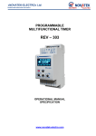
«NOVATEK-ELECTRO» LTD Intellectual Industrial Electronics RMT-102 MAXIMAL CURRENT RELAY OPERATING MANUAL CERTIFICATE Manufacture Quality Control System comply with the requirements of ISO 9001:2008 Review the Operating manual before using the unit. NEVER ATTEMPT TO REMOVE AND REPAIR THE UNIT. Some of the unit components may be live. NEVER ATTEMPT TO OPERATE THE UNIT WITH THE MECHANICAL DAMAGE OF THE HOUSING. DO NOT LET WATER INTO THE UNIT. UNPLUG THE UNIT BY DISCONNECTING THE POWER CORD FOR TROUBLESHOOTING, MAINTENANCE, OR INSTALLATION WORKS. WARNING! THE UNIT SHOULD BE OPERATED IN THE ELECTRIC MAINS PROTECTED WITH AUTOMATIC CIRCUIT BREAKER. This unit is safe for use in case of compliance with operating rules. Odessa city, www.novatek-electro.com ~2~ 1 Aperture for wire conductor which current is measured by RMT-102 2 Power input of RMT-102 – ~220V/50Hz 3 Outputs of load-control relay, max. ~250V, 8A. 4 LED indicator «Load» 5 Digital Indicator for measurable and controlled parameters 6 Range switch - 40/400A of adjuster «over current adjustment» 7 Toggle for switch of indication modes «current now» /«maximal current» 8 LED indicator «Over current» 9 Adjustment knob for «load reclosing delay setting» – ton 10 Adjustment knob for «maximal current setting» – Imax Figure 1 – External view of RMT-102 1 DESCRIPTION AND OPERATION 1.1. APPLICATION RMT-102 is designed to perform the permanent control of active value of current of single-phase load in range from 1 to 400A and to turn OFF it in case of excess of user adjusted maximum allowed load current (with independent time lag) with preset cut-OFF time and subsequent automatic insertion with preset turn-ON time or with block of reclosing. Current setting reaction time of relay and auto reclosing time (ART) are adjusted by the user using potentiometers on the front panel of RMT-102. Measurement is carried out by built-in current sensor without break of electrical circuit with the use of current transformer connected to RMT-102. RMT-102 can be used as: - digital ammeter; - limit relay of input current; - selection relay of priority load. In RMT-102 for current measuring it is used a built-in current transformer. RMT-102 allows controlling current values and condition of load per LED indicators on the front panel. 1.2. GENERAL TECHNICAL CHARACTERISTICS OF RMT-102 Operation supply voltage, V Maximal allowed voltage, not more, V Operation voltage range at which RMT-102 will keep working, V* Power frequency, Hz Current measurement range, A Measurement inaccuracy, not worse than Adjustment range а) Imax, А Absolute measurement accuracy of current, A, no more than б) Imax, A Absolute measurement accuracy of current, A, no more than Adjustment range of ton, sec Time of turn off delay, sec PMT-102 220 400 from 130 to 300 47 53 1-400 1% 1 40 ±1 10 - 400 ±4 0 900, ∞ 4 NOVATEK-ELECTRO ~3~ Readiness time, sec, no more than 0,5 Power consumption (under load), VA, no more than 3,0 Commutation over current of the output contacts at cosφ=1, A 8 Commutation life of output contacts: - under 5A power load, times, no less than 100 000 - under 1A, power load, times, no less than 1 000 000 Protection class: - Device IP40 - Connection terminal IP20 Climatic design UHL4 From -35 to +55 Operational temperature range, С From -55 to +70 Storage temperature, С Weight, kg, no more than 0,200 Outer dimensions 53 х116 х 75 Positioning in space: User-defined __________ *In RMT-102 the indicator switching-off (item 5, fig. 1) is provided at supply voltage decrease lower than 130 V and blocking of functioning of RMT-102 at a supply voltage reduction lower than 100 Volt. 1.3. DESIGN AND OPERATION When putting the supply current of 220V, 50 Hz to the terminals 4-5 (item 2, fig.1), on RMT-102 the turning ON of load takes place in readiness time not more than 0,5 s: contact 2-3 opens, contact 1-2 closes (item 3 fig.1), LED indicator «Load» lights ON (item 4, fig.1), and value of load current is displayed on the digital indicator (item 5, fig.1). When the current value exceeds the maximal current setting, the LED indicator “Overload” will light ON in red color (item 8, fig.1) and counting off for power cut delay will begin (4 s), thus Load current value (in ampere) and remaining time to power cutting (in seconds) will be alternately displayed on the digital indicator (item 5, fig.1). The value of maximal current is adjusted by the knob «Maximal Current Setting» (item 10, fig.1) in both ranges: from 10 to 400A and from 1 to 40 A, a range choice is carried out by a range switch (item 6, fig.1). When period of power cut delay is finished then the load will be cut-OFF and contact 1-2 opens, contact 2-3 closes, green LED indicator «Load» – lights OFF. If current value comes back to range lower setting of maximal value the LED indicator «Over load» lights OFF, a count-down of load reclosing delay will begin (from 0 to 900 seconds), it is adjusted by the knob «setting of load reclosing delay setting», (item 9, fig.1). The remaining time to turn-ON (in seconds) will be displayed on the digital indicator (item 5, fig.1). If during power cutting the current does not come back to a preset range, then a message ‘Err’ will be displayed on the digital indicator (item. 3, fig.1) and count-down of reclosing time will NOT begin. When time delay is finished, load will be turn-ON and contact 2-3 will be opened, contact 1-2 will be closed, “Load” LED indicator will light ON, and a load current will be displayed on the digital indicator. During twisting of any adjustment knob (item 9, fig. 1) a value of adjusted parameter is showed on the digital indicator, in this case a decimal dot will be in less significant digit. If adjustment knob for reclosing delay sitting (item 9, fig. 1) stays in “inF” position (infinity sing “∞” on the scale) auto reclosing is disabled and ‘inF’ is displayed on the digital indicator (item 5, fig. 1) (auto reclosing is blocked). To turn-ON load the RMT-102 should be short cut-OFF or user should set adjustment knob (item 9, fig.1) for auto reclosing sitting in position which is different from ’inF’ position. After change position of reclosing delay sitting knob to blocking auto reclosing (infinity sing “∞” on the scale (item 9, fig.1)) “inF” will be displayed for 4 seconds on the digital indicator. RMT-101 is able to show maximal value of current. If toggle (item 7, fig.1) for selecting the indication mode between “actual current” and “maximal current” is set in “Imax” position, then maximal value of current will be displayed on the digital indicator (item 3, fig.1). This maximal value corresponds to maximal fixed value of current from instant of energizing RMT-102 or from instant of restore of calculation maximal current value. Restore of calculation of maximal current value is carried out simultaneously with adjustment of ‘indI’ toggle in “current” position. 2 SCOPE OF USE 2.1 PREPARATION OF RMT-102 RELAY FOR USE 2.1.1 Safety Rules ATTENTION!!! All connection and disconnection works must be done only on deenergized RMT-102 according to safety regulations! IT IS FORBIDDEN TO OPEN AND REPAIR THE DEVICE BY UNAUTHORIZED PERSONNEL. IT IS NOT ALLOWED TO USE THE DEVICE IF IT HAS THE MECHANICAL DAMAGES OF CASE. NOVATEK-ELECTRO PMT-102 ~4~ Figure 2 – Wiring Diagram of RMT-102 2.1.2 Start-up Preparation of RMT-102 Connect the device RMT-102 according to the wiring diagram (Figure 2). A wire (current of which is controlled) should be passed through a corresponding aperture of case. Adjust a range of change overcurrent sitting using range switch (item 6, fig. 1), also adjust a cut-OFF time sitting, reclosing time and value of overcurrent using adjustment knobs (items 9, 10, fig. 1). 2.1.3 Relay work Turn ON the supply power to the RMT-102. If necessary, make a fine adjustment of value sittings to control of which a digital indicator (item 5, fig. 1) is used. RМТ-102 is ready for work. To increase a convenience of adjustment parameters scale of reclosing delay sitting ‘ton’ (item 9, fig. 1) has 2 ranges are 0 to 100 and 100 to 900 seconds, scale of power- cut delay sitting ‘toff’ is also divided in 2 ranges are 0 to 50 and 50 to 300 seconds with different divisions value. 3 TRANSPORTATION AND STORAGE RМТ-102 should be stored in a factory package in enclosed rooms with ambient temperature from - 55 to +70 °C and exposed to not more than 80% of relative humidity. There should be no fumes in the air that may exert a deleterious effect on package and the RMT-102 components. The Buyer must provide the protection of the relay against possible mechanical damages in transit. 4 WARRANTY PACKAGE Operation life of RMT-102 is no less than 10 years. Warranty period of device operation is 36 months from the date of sale. During warranty period the manufacturer will make repair free of charge provided the user observed the requirements of the user manual. No warranty service is provided in following cases: The period of warranty has expired; the presence of mechanical damages; there are traces of moisture attack or foreign objects inside the device; unauthorized opening and repair of the device; damage due to electric current or voltage which value was over those indicated in the user manual. The warranty service shall be provided at the location of purchase. The Post Warranty Service of the device is provided by Novatek-Electro Ltd. under a separate agreement. 5 ACCEPTANCE CERTIFICATE The device of Maximal Current Relay RMT-102 is made and approved according to the requirements of the applicable technical specifications and is accepted as ready for operation. PMT-102 NOVATEK-ELECTRO


