1
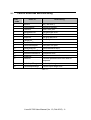
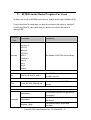
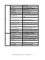
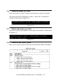
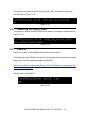
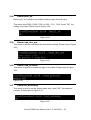
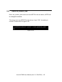
Linux M-7000
Linux M-7000 User Manual
Warranty
All products manufactured by ICP DAS are warranted
against defective materials for a period of one year from
the date of delivery to the original purchaser.
Warning
ICP DAS assume no liability for damages consequent
to the use of this product. ICP DAS reserves the right to
change this manual at any time without notice. The
information furnished by ICP DAS is believed to be
accurate and reliable. However, no responsibility is
assumed by ICP DAS for its use, nor for any infringements
of patents or other rights of third parties resulting from its
use.
Copyright
Copyright 2015 by ICP DAS. All rights are reserved.
Trademark
The names used for identification only may be
registered trademarks of their respective companies.
Linux M-7000 User Manual (Ver 1.0, Feb.2015)…1
Tables of Content
目錄
1.
2.
M-7000 lib compile & default setting............................................................ 4
1.1
M-7000 lib compile ................................................................................ 4
1.2
M-7000 default setting.......................................................................... 4
M-7000 Serial static Library Function Description................................... 5
2.1
Table of ErrorCode and ErrorString................................................. 6
2.2
System Functions ................................................................................. 7
2.2.1
2.2.2
2.2.3
3.
Open_Com .................................................................................. 7
modbusRequest ........................................................................ 7
Close_Com.................................................................................. 8
M-7000 series Demo Program For Linux .................................................... 9
3.1
Demo Modbus_utility ......................................................................... 11
3.2
Demo setmodebus .............................................................................. 11
3.3
Demo getmodbus ................................................................................ 11
3.4
3.5
3.6
3.7
Demo do ................................................................................................ 12
Demo multi_do..................................................................................... 12
Demo do_readback............................................................................. 12
Demo di .................................................................................................. 13
3.8
3.9
Demo di_counter ................................................................................. 13
Demo firmware_ver ............................................................................ 13
3.10
3.11
Demo module_name .......................................................................... 14
Demo set_mod_add............................................................................ 14
3.12
3.13
Demo set_comm_set ......................................................................... 14
Demo read_comm_set ....................................................................... 15
3.14
3.15
3.16
3.17
3.18
Demo set_di_counter_trig ................................................................ 15
Demo read_di_counter_trig.............................................................. 15
Demo set_power_on_value .............................................................. 16
Demo read_power_on_value ........................................................... 16
Demo set_dio_actice_states ............................................................ 16
3.19
3.20
3.21
3.22
Demo read_dio_active_states ......................................................... 17
Demo ao................................................................................................. 17
Demo ao_readback ............................................................................. 18
Demo ao_set_power_on_value ....................................................... 18
Linux M-7000 User Manual (Ver 1.0, Feb.2015)…2
3.23
3.24
3.25
3.26
Demo modules_name ........................................................................ 18
Demo multi_ao ..................................................................................... 19
Demo read_dev_set ............................................................................ 19
Demo read_protocol........................................................................... 19
3.27
3.28
Demo set_watchdog........................................................................... 19
Demo set_module_add ...................................................................... 20
Linux M-7000 User Manual (Ver 1.0, Feb.2015)…3
1. M-7000 lib compile & default setting
1.1
M-7000 lib compile
Step 1: Download the Linux Modbus lib “m7k.tar.gz” from ICP DAS website to
the linux system.
Step 2: Decompress the tarball “m7k.tar.gz”.
Step 3: Type ‘cd’ to m7k directory.
Step 4: Type ‘make’ or ‘make Device=USB’ to compile the package.
(Parameter -s means silent the command)
command ‘make‘ use libm7k.a lib, you can use /dev/ttyS* device file to
send receive Modbus protocol.
command ‘make Device=USB’ use libm7k_usb.a lib, you can use
/dev/ttyUSB* device file to send receive Modbus protocol.
Please refer to the Figure 1-1.
Figure 1-1
1.2
M-7000 default setting
Protocol: Modbus RTU.
Module Address: 01.
DIO Type: 40.
Analog output type:Type 32, 0~10V.
Analog Input type: Type 08,-10V~10V.
Checksum disable.
Baud Rate: 9600 bps.
Linux M-7000 User Manual (Ver 1.0, Feb.2015)…4
2. M-7000 Serial static Library Function
Description
The static library is the collection of function calls of the M-7000 Series. The
application structure is presented as below figure “Figure 2-1”. The user
application program developed by C (C++) language can call library “libm7k.a”
or “libm7k_usb.a” for M-7000 Series in user mode. And then static library will
call the module command to access the hardware system.
User's Application
Function Call into Library
Development
Toolkit
Static library “libm7k.a” or
“libm7k_usb.a”
Services Call into Kernel-Mode
Com port Device Driver
Device Control
Hardware Devices
Figure 2-1
Linux M-7000 User Manual (Ver 1.0, Feb.2015)…5
2.1
Table of ErrorCode and ErrorString
Error
code
Error ID
Error String
0
NoError
OK ( No error !)
1
FunctionError
2
PortError
Use error function.
Open error port.
3
BaudRateError
Set baud rate error.
4
DataError
Set Data bits error.
5
StopError
Set Stop bits error.
6
ParityError
Set Parity bits error.
7
CheckSumError
Check sum error.
8
ComPortNotOpen
Com port not open.
10
SendCmdError
12
Send command error.
ReadComStatusError Receive command status error.
ResultStrCheckError Checksum error.
13
CmdError
Send error command.
15
TimeOut
Exceeds predetermined time and no
response.
19
UnderInputRange
Under input range error.
20
ExceedInputRange
Exceed input range error.
11
Table 1-1
Linux M-7000 User Manual (Ver 1.0, Feb.2015)…6
2.2
System Functions
2.2.1
Open_Com
Description:
Open specific device with device file.
Syntax:
Open_Com(char port, DWORD baudrate, char cData,
char cParity, char cStop);
Parameter:
port: Set com port number.
baudrate: Set specific baudrate. (1200~115200)
cData: Set Data bits.
cParity: Set Parity bits.
cStop: Set Stop bits.
Return:
“PortError”,
“BaudRateError”,
“DataError”,
“ParityError”,
“StopError”,
“NoError”.
2.2.2
modbusRequest
Description:
Send Modbus protocol request.
Syntax:
modbusRequest(char cPort, char cNetID, char cFunction, WORD
wAddr, WORD wCount, unsigned char szBuf[],
WORD wBufLen, WORD wTimeout, WORD *wT)
Parameter:
cPort: Choose com port number to send.
cNetID: Device NetID.
cFunction: Modbus RTU protocol function code.
wAddr: Address mapping.
wCount: Channel numbers
szBuf[]: Set address value and receive response.
wBufLen: szBuf[] length.
Linux M-7000 User Manual (Ver 1.0, Feb.2015)…7
wTimeout: Set timeout.
*wt: response time(ms).
Return:
“UnderInputRange”,
“ExceedInputRange”,
“FunctionError”,
“TimeOut”,
“ReadComStatusError”,
“ResultStrCheckError”,
“CmdError”,
“NoError”.
2.2.3
Close_Com
Description:
Close specific device with device file.
Syntax:
Close_Com(char port)
Parameter:
port: Set com port number.
Return:
“FunctionError”,
“PortError”,
“NoError”.
Linux M-7000 User Manual (Ver 1.0, Feb.2015)…8
3. M-7000 series Demo Program For Linux
All demo are work on M-7000 series device, and protocol type is Modbus RTU.
If you linked libm7k.a,and then you should use device file name is /dev/ttyS*
If you linked libm7k_usb.a,and then you should use device file name is
/dev/ttyUSB*
Directory
Path
File Name
Description
codes.h
common.h
crc16.h
Include
debug.h
m7000.h
m7k.h
modbus.h
The header of M-7000 series library.
msw.h
sio.h
slot.h
timer.h
lib
libm7k.a & libm7k_usb.a
Doc
Linux_M-7000_Manual.pdf
The M-7000 series library
for x86 Linux PC.
The linux manual for M-7000
Series.
examples dir
getmodbus
common
setmodbus
Modbus_utility
Send Modbus protocol to get device
information.
Send Modbus protocol to set value to
the device.
Get module name, NetID and
baudrate.
Linux M-7000 User Manual (Ver 1.0, Feb.2015)…9
di
Read di status.
di_counter
Read di trigger counters.
do
Set value to single do channel.
do_readback
Read do status.
firmware_ver
Read firmware version.
module_name
Read module name.
multi_do
Set value to multiple do channels.
read_comm_set
dio
protocol.
read_di_counter_trig
Read the digital input counter trigger
edge value of a module.
read_dio_active_stats
Read the DI/O active states of a
module.
read_power_on_value
Read the power-on value of a module.
set_comm_set
set_di_counter_trig
aio
Get module info with baud rate and
Set module info with baud rate and
protocol.
Set the digital input counter trigger
edge value of a module.
set_dio_actice_state
Set the DI/O active states of a module.
set_power_on_value
Set the power-on value of a module.
set_mod_add
Set the address of a module.
ao
Set value to single ao channel.
ao_readback
Read ao status.
ao_set_power_on_value
Set the power-on value of a module.
modules_name
Read module name.
multi_ao
Set value to multiple ao channels.
read_dev_set
Get module info with baud rate and
DPS bits..
read_protocol
Read protocol of a module.
set_watchdog
Enable/Disable watchdog.
Linux M-7000 User Manual (Ver 1.0, Feb.2015)…10
3.1
Demo Modbus_utility
This demo is used to detect device and show module name, NETID, baud rate.
Please refer to Figure 3-1
Figure 3-1
3.2
Demo setmodebus
This demo is used to set value to specific address. Please refer to Figure 3-2.
Figure 3-2
This command is set to analog output channel 0 value 6000, and time out
100ms.
3.3
Demo getmodbus
This demo is used to get value to specific address. Please refer to Figure 3-3
Figure 3-3
This command is read analog channel channel 1 value.
Linux M-7000 User Manual (Ver 1.0, Feb.2015)…11
3.4
Demo do
Demo do is used to set single digital output channel on or off.
This demo set channel 0 on, if print “OK”, the setting is success. Please refer
to Figure 3-4.
Figure 3-4
3.5
Demo multi_do
Demo multi_do is used to set multiple digital output on or off.
This demo set channel 0 & 1 on, if print “OK”, the setting is success. Please
refer to Figure 3-5.
Figure 3-5
3.6
Demo do_readback
Demo do_readback is used to read digital output channel status
This demo read digital output channel from CH0~CH3. Please refer to Figure
3-6.
Figure 3-6
Linux M-7000 User Manual (Ver 1.0, Feb.2015)…12
3.7
Demo di
Demo di is used to read digital input channel status.
This demo read digital input channel from CH0~CH3. Please refer to Figure
3-7
Figure 3-7
3.8
Demo di_counter
Demo di_counter is used to read di trigger counters.
This demo read digital input channel counters from CH0~CH3. Please refer to
Figure 3-8.
Figure 3-8
3.9
Demo firmware_ver
This demo is used to read firmware version. Please refer to Figure 3-9.
Figuer 3-9
Linux M-7000 User Manual (Ver 1.0, Feb.2015)…13
3.10
Demo module_name
This demo is used to read device module name. Please refer to Figure 3-10
Figure 3-10
3.11
Demo set_mod_add
Demo set_mod_add is used to set new NETID to the dio device, NETID will be
changed Immediate.
This demo is set new NETID 2 to the device, if print ”OK”, the setting is
success. Please refer to Figure 3-11.
Figure 3-11
3.12
Demo set_comm_set
Demo set_comm_set is used to set baud rate and protocol of a module, those
two settings will active when re-power.
This demo is set baud rate 115200 to the device, if print ”OK”, the setting is
success. Please refer to Figure 3-12.
Figure 3-12
Linux M-7000 User Manual (Ver 1.0, Feb.2015)…14
3.13
Demo read_comm_set
This demo is used to read baud rate and protocol. Please refer to Figure 3-13
Figure 3-13
3.14
Demo set_di_counter_trig
Demo set_di_counter_trig is used to set the digital input counter trigger edge
value of a module, this setting will be changed Immediate.
1 = rising edge, 0 = falling edge. For example 0x03 denotes that channels 0~1
are set as rising edge and channels 2~3 are set as falling edge.
This demo is set digital input CH0~Ch4 rising edge to the device, if print ”OK”,
the setting is success. Please refer to Figure 3-14.
Figure 3-14
3.15
Demo read_di_counter_trig
This demo is used to read digital input channel counter trigger edge value of a
module. Please refer to Figure 3-15.
Figure 3-15
Linux M-7000 User Manual (Ver 1.0, Feb.2015)…15
3.16
Demo set_power_on_value
Demo set_power_on_value is used to set the power-on value of a module.
This demo is set CH0~CH3 power on value 1, if print ”OK”, the setting is
success. Please refer to Figure 3-16.
Figure 3-16
3.17
Demo read_power_on_value
This demo is used to read power on value status of the device 0. Please refer
to Figure 3-17.
Figure 3-17
3.18
Demo set_dio_actice_states
Demo set_dio_actice_state is used to set the DI/O active states of a module.
Linux M-7000 User Manual (Ver 1.0, Feb.2015)…16
This demo is set value 0 to the device, if print ”OK”, the setting is success.
Please refer to Figure 3-18.
Figure 3-18
3.19
Demo read_dio_active_states
This demo is used to read the DI/O active states of a module. Please refer to
Figure 3-19.
Figure 3-19
3.20
Demo ao
Demo ao is used to set single analog output channel value.
This demo set value 5000 to the device, you should check type code and value
range, you can refer address mapping below link.
http://www.icpdas.com/products/Remote_IO/m-7000/address_mapping/m700
0_address_mapping.pdf
Please refer to Figure3-20.
Figure 3-20
Linux M-7000 User Manual (Ver 1.0, Feb.2015)…17
3.21
Demo ao_readback
Demo ao_readback is used to read analog output channel value.
Thid demo read value from CH0~CH1. Please refer to Figure 3-21.
Figure 3-21
3.22
Demo ao_set_power_on_value
Demo ao_set_power_on_value is used to set analog output channel power on
value.
This demo is set analog output CH0 power on value 2500, if print ”OK”, the
setting is success. Please refer to Figure 3-22.
Figure 3-22
3.23
Demo modules_name
This demo is used to read aio device module name. Please refer to Figure
3-23
Figure 3-23
Linux M-7000 User Manual (Ver 1.0, Feb.2015)…18
3.24
Demo multi_ao
Demo multi_ao is used to set multiple analog output channel value.
This demo is set 5000, 10000, 7500, to CH0、CH1、CH2, if print ”OK”, the
setting is success. Please refer to Figure 3-24.
Figure 3-24
3.25
Demo read_dev_set
This demo is used to read baud rate and data bit setting. Please refer to Figure
3-25.
Figure 3-25
3.26
Demo read_protocol
This demo is used to read protocol type of a module. Please refer to Figure
3-26.
Figure 3-26
3.27
Demo set_watchdog
This demo is used to set aio device watch dog, if print ”OK”, the setting is
success. Please refer to Figure 3-27.
Figure 3-27
Linux M-7000 User Manual (Ver 1.0, Feb.2015)…19
3.28
Demo set_module_add
Demo set_module_add used to set new NETID to the aio device, NETID will
be changed Immediate.
This demo is set new NETID 2 to the device, if print ”OK”, the setting is
success. Please refer to Figure 3-28.
Figure 3-28
Linux M-7000 User Manual (Ver 1.0, Feb.2015)…20