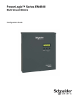
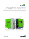
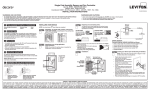
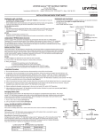
1
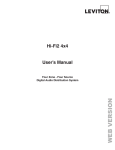
Series 8000 Multi-Point High Density Meter Installation and User’s Manual Version 2.0 1. INTRODUCTION ...................................................................................................................... 3 1.2 Meter Features System Description ...................................................................................... 3 1.3 Series 8000 System Specifications ........................................................................................ 3 2. SAFETY PRECAUTIONS ......................................................................................................... 9 2.1 Electrical Safety Compliance .............................................................................................. 10 3. INSTALLATION ..................................................................................................................... 10 3.1 Pre-Installation .................................................................................................................... 10 ................................................................................................................................................... 22 4. Delta service metering .............................................................................................................. 26 5. Installing the Current Transformers .......................................................................................... 27 6. Connecting the Ethernet Communications ............................................................................... 27 7. Connecting the Modbus RTU Communications ....................................................................... 28 8. Start-Up Sequence .................................................................................................................... 29 8.1 Manually Testing Communications .................................................................................... 29 9. Pulse Inputs ............................................................................................................................... 30 10. Display Navigation ................................................................................................................. 30 10.1 Normal Mode .................................................................................................................... 30 10.2 Diagnostics Mode.............................................................................................................. 30 11. CONFIGURATION TOOL CONFIGURATION............…………………………………...32 12. CONTACT INFORMATION ................................................................................................. 33 13. REGULATORY COMPLIANCE .......................................................................................... 36 Leviton Manufacturing Co., Inc. 2 1. INTRODUCTION This document describes the Series 8000; including procedures to install and start up the unit, and complete the initial configuration: “System Description” “Pre-Installation” “Installation Procedures” “Start-Up Sequence” “Fuse Replacement” This documentation is intended for those responsible for installing and configuring the Series 8000 meters. Installers must be qualified electricians with knowledge of local and national code requirements. See “Safety Precautions”. 1.2 Meter Features System Description The Series 8000 meters support: Single-phase, 2-wire Single-phase, 3-wire (network) Three-phase wye and Delta services Depending on how the meters are installed and configured, they can meter 8, 12, or 24 individual meter points. The Series 8000 meters are designed for residential, commercial, and industrial use and display the power and consumption readings for each measurement point. 1.3 Series 8000 System Specifications The Series 8000 system architecture includes: Single-phase, 2-wire; single-phase, 3-wire (network); and three-phase compatibility 120/208V, 120/240V and 277/480V configurations, and 347/600V with external potential transformers Up to 8, 12, or 24 individual meter points Local Ethernet configuration interface via PC and web browser Ethernet ports for remote reporting Modbus serial port for remote reporting Serial port for remote display 2 pulse inputs to connect metering devices Table 1 lists the system specifications of the Series 8000 Leviton Manufacturing Co., Inc. 3 Table 1: Series 8000 Meter System Specifications Specification Series 8000 Series 8000 Model: S8UTS Model: S8UWH Leviton Manufacturing Co., Inc. 4 Front Panel Display The Series 8000 meters have the following front panel features (Figure 1 shows the Series 8000 front panel): • LCD — displays 2 rows of 16 characters for each of the meter points (8, 12, or 24) • Display button — cycles through the available information for each of the meter points • Left and right arrow buttons — selects which of the meter points is on the display Figure 1: Series 8000 front panel Leviton Manufacturing Co., Inc. 5 Figure 2 shows the internal view of the Series 8000 Figure 2: Series 8000 internal view (Meter Only) Leviton Manufacturing Co., Inc. 6 Figure 3 shows the dimensions of the Potential Transformer, Series 8000 Meter and CT Termination enclosure Figure 3: Product Dimensions Leviton Manufacturing Co., Inc. 7 Figure 4 shows the a functional Diagram of how all possible components fit together for a 3 phase 3 wire installation Figure 4: Product Dimensions PT Enclosure (Optional)* Series 8000 CT Termination Enclosure 8000 Leviton Manufacturing Co., Inc. 8 2. SAFETY PRECAUTIONS Carefully observe these safety instructions. Leviton Manufacturing Co., Inc. 9 2.1 Electrical Safety Compliance Use the unit only in accordance with the electrical power rating The unit is only to be installed by a qualified electrician Initial installation of the unit must be inspected by the local electrical Inspection Authority Install the unit in compliance with the following local and national electrical codes: o Canada: Canadian Electrical Code, Part I, CSA C22.1 o United States: National Fire Protection Association (NFPA) 70; US National Electrical Code o Elsewhere: International Electrotechnical Commission (IEC) 364, Part 1-7 Ensure that the unit is properly earthed If the equipment is installed or used in a manner other than that specified in this document, it may void your warranty or impair the protection of the equipment. 3. INSTALLATION This section contains the following installation topics: “Pre-Installation” “Installation Procedures” “Start-Up Sequence” 3.1 Pre-Installation The pre-installation checklist and site planning must be performed before installing the equipment at the site. 3.1.1 Pre-Installation Checklist The installer must provide the following information, tools, and equipment before proceeding with the installation: o o o o o o Certified current transformers for metering An appropriate 15-Amp maximum circuit breaker or a fused disconnect Switch for the type of panel Current/voltage meter to test the phasing of panel RJ45 Ethernet patch cable 4-wire 14 AWG (1.63 mm2) cable for three-phase wye connected circuits, or 3wire 14 AWG (1.63 mm2) cable for a single-phase wye connected circuits mall flat-head screwdriver Leviton Manufacturing Co., Inc. 10 o o o o o 3.1.2 Crimping tool #2 Phillips screwdriver 18 AWG butt splice connector Wire strippers Four 1-inch (25 mm) #8 mounting screws suitable for selected mounting surface Site Planning 1. Determine the number of S8000 meters to be installed and ensure adequate space. 2. Determine the number of Modbus RTU or Ethernet drops required, and ensure they are installed before installing the S8000 meters 3. Determine the number and types of meters or monitors required (single-phase, network, or three-phase). 4. Determine the model number and correct sense voltage based on the voltage label on the top right side of the unit. 3.1.3 Access to Power and Lighting The installation site must be supplied with access to the main electrical panel and any sub-panels. Portable or permanent lighting must be available to provide the installers with a clear view of the equipment and of the installation environment. Each installation may vary depending on physical site restrictions. 3.1.4 Installation Procedures This section provides information about activities that must be performed to install the Series 8000 meters in a single-phase 2-wire, single-phase 3-wire (network), or threephase 4-wire application. The installation procedures must be performed in the following order: 1. 2. 3. 4. 5. 6. 7. “Mounting the S8000 Meters” “Installing Potential Transformers for Three-Phase Service Greater Than 277V” “Installing the Sense Voltage and Control Voltage Cables in Wye and Delta Services” “Installing the Current Transformers” “Connecting the Ethernet Communications” “Connecting the Modbus RTU Communications” “Start-Up Sequence” Leviton Manufacturing Co., Inc. 11 8. “Completing the installation record” 3.1.5 Mounting the Series 8000 Meters Figure 5 shows the general mounting layout for metering 120V/208V wye services, and Figure 6 shows the general mounting layout for metering 347V/600V wye services. 1. Mount the Series 8000 meter and the shorting block enclosure adjacent to the main circuit breaker box using the 1-inch (25-mm) #8 screws. If mounting the unit on a plasterboard surface, use cylinder plugs. 2. Remove the front cover from the meter by removing the four screws with a #2 Phillips screwdriver. Retain the cover and screws for later re-installation. 3. Mount the Series 8000 meter on the wall and secure it by inserting a screw in each mounting keyhole and tightening the screws. 4. Mount the shorting block enclosure on the wall as shown in Figures 3 and secure it by inserting a screw in each mounting keyhole and tightening the screws. In Figure 4, the meter is powered and takes its sense voltage directly from a breaker within the panel. Leviton Manufacturing Co., Inc. 12 Figure 4: 120V Mounting Layout, Dimensions and Clearances Leviton Manufacturing Co., Inc. 13 3.1.6 Installing Potential Transformers for 3PH Service Greater than 277V Potential transformers are required when metering services greater than the rated input of the meter. Potential transformers are used to reduce the line-to-neutral voltage of the service to 120V. The accuracy class should be 0.3% or better, with a burden rating of 30VA. For applications in Canada, Measurement Canada approved potential transformers are required. Measurement Canada requires an accuracy class of 0.3% or better, with a 150VA rating. NOTE: Potential transformer burden depends on the control voltage source. If control voltage is provided separately (not derived from the metered voltage), t hen lower transformer burden may be acceptable. Contact your local Leviton representative for details. Potential transformers must be mounted in a listed electrical enclosure as shown in Figure 5. Figure 5: Potential transformer chassis From the Breaker Panel Leviton Manufacturing Co., Inc. To Series 8000 14 Mount the potential transformer enclosure between the supply voltage and the Series 8000 meters as shown in Figure 5. Transformer configuration must be Y||Y (wyewye). In Figure 6, the meter is powered from the potential transformers that are fed from a breaker within the 347V/600V panel. The CT cable is connected to the shorting enclosure before connecting to the CTs in the panel. Figure 6: Typical 3-PH 347V installation Leviton Manufacturing Co., Inc. 15 3.1.7 o o o o o o Installing the Sense Voltage and Control Voltage Cables in Wye and Delta Services The sense voltage (A, B, C, N) provides phase voltages for metering. The configuration depends on the type of service being metered: See “For a single-phase panel with the 120V variant of the meter:” See “For a 120/208V three-phase wye panel with the 120V variant of the meter:” See “For a 240/416V three-phase wye panel with the 230/240V variant of the meter.” See “For a 277/480V three-phase wye panel with the 120V variant of the meter.” See “For a 347/600V or higher three-phase wye panel with potential transformers with the 120V variant of the meter.” See “For a three-phase Delta panel with the 120V variant of the meter.” The Series 8000 meters are shipped from the factory with a control voltage jumper that can be used to connect the control voltage input and the sense voltage inputs to provide control voltage to the unit. The following procedures explain how to connect the sense voltage inputs for each of the service types. For a single-phase panel, use a 3-wire (red, black, white), 14 AWG (1.63 mm2), 90°C (194°F) cable. For a three-phase panel, use a 4-wire (red, black, blue, white), 14 AWG (1.63 mm2), 90°C (194°F) cable. For a Delta service, use a 3-wire (red, black, blue), 14 AWG (1.63 mm2), 90°C (194°F) cable. Metallic, flexible armored cable (BX cable) is recommended for commercial installations as shown in Figure 6 on page 14. The Series 8000 meters must be connected to the sense voltage and control voltage through a properly rated disconnect that disconnects all line and neutral wires, so it can be powered down. The disconnect must be located within easy reach of the meter operator, and must be labeled as such. Opening the disconnect or breaker is the disconnect device. For multiple Series 8000 meter installations, the same disconnect can be used to power all meters, and must be labeled for all meters it supplies power to. The disconnect device must meet IEC 60947-1, IEC 60947-3 and/or comply with the local electrical code. Leviton Manufacturing Co., Inc. 16 To install the control voltage cable in a 120/208V or 120/240V application: NOTE: If the circuit breaker panel does not designate phase A, phase B and phase C feeds, make your own designation and use it for the rest of the installation. 1. Before connecting the sense voltages, turn off the power to the circuit being connected. 2. Always use a properly rated voltage sensing device to confirm power is off. 3. Connect the sense voltages phase A, B, C, and N leads from the voltage disconnect to the meter as described in Figure 6 on page 14 and Figure 7 on page 15. NOTE: The phase wiring sequence A, B, C between the Series 8000 meter and the panel must match or the measurement readings will be wrong 4. If more than one meter is being installed, repeat this procedure for each additional meter. Leviton Manufacturing Co., Inc. 17 For a single-phase panel with the 120V variant of the meter: o Connect meter terminal A to the voltage disconnect phase A (red wire) o Connect meter terminal B to the voltage disconnect phase B (black wire) o Connect meter neutral terminal to neutral bar in the voltage disconnect panel (white wire) o Connect earth wire to earth post using lug provided o Meter terminal C is not connected o Install power supply shorting jumpers (see Figure 7) The Series 8000 meters are rated for direct input of 120V to 277V 60Hz phase potential. When metering services greater than 120V, the meter is powered from a separate 120V instrument transformer. Figure 7: Series 8000 meter in a 120/240V single-phase connection Leviton Manufacturing Co., Inc. 18 For a 120/208V three-phase wye panel with the 120V variant of the meter: o Connect meter terminal A to the voltage disconnect phase A (red wire) o Connect meter terminal B to the voltage disconnect phase B (black wire) o Connect meter terminal C to the voltage disconnect phase C (blue wire) o Connect meter neutral terminal to neutral bar in the voltage disconnect panel (white wire) o Connect earth wire to earth post using lug provided o Install power supply shorting jumpers (see Figure 8) Figure 8: S8000 meter 120/208V three-phase wye service connection Leviton Manufacturing Co., Inc. 19 For a 120/208V three-phase wye panel version with no shorting blocks: Leviton Manufacturing Co., Inc. 20 For a 240/416V three-phase wye panel with the 230/240V variant of the meter: o Connect meter terminal A to the voltage disconnect phase A (red wire) o Connect meter terminal B to the voltage disconnect phase B (black wire) o Connect meter terminal C to the voltage disconnect phase C (blue wire) o Connect meter neutral terminal to neutral bar in the voltage disconnect panel (white wire) o Connect earth wire to earth post using lug provided o Install power supply shorting jumpers (see Figure 9) Figure 9: Series 8000 meter 240/416V three-phase wye service connection Leviton Manufacturing Co., Inc. 21 For a 277/480V three-phase wye panel with the 120V variant of the meter: o Connect meter terminal A to the voltage disconnect phase A (red wire) o Connect meter terminal B to the voltage disconnect phase B (black wire) o Connect meter terminal C to the voltage disconnect phase C (blue wire) o Connect meter neutral terminal to neutral bar in the voltage disconnect panel (white wire) o Connect earth wire to earth post using lug provided o From the auxiliary power transformer, connect 120V auxiliary power to AUXA and AUXN on the meter (see Figure 10) Figure 10: S8000 meter 277/480V three-phase wye service connection Leviton Manufacturing Co., Inc. 22 For a 277V/480V three-phase wye service panel with the 277V variant of the meter: o Connect the sense voltage phase A (red wire) to the step down transformer terminal A o Connect sense voltage B to the sense voltage connector J3 phase B (black wire) o Connect sense voltage C to the sense voltage connector J3 phase C (blue wire) o Connect sense voltage N to step down transformer terminal N (white wire) o Connect the earth wire to earth post using lug provided o Check the 277V Input box on the UL label on the Series 8000 chassis (see figure 11) Figure 11: 277/480V WYE wiring A N C B A N Leviton Manufacturing Co., Inc. 23 To convert the 277V Series 8000 to a 120V Series 8000 meter: o o o o o Remove phase A and neutral from the sense voltage input terminal Remove the white jumper connector from J2 Remove step down transformer by removing mounting plate from the meter base See figure below Check the 120V Input power box on the UL label on the Series 8000 chassis (see figure 12) Note: Refer to Installation Manual for the 120V wiring options of the Series 8000 to complete the install. Figure 12: 120 wiring conversion Leviton Manufacturing Co., Inc. 24 For a 347/600V or higher 3PH wye panel with potential transformers with the 120V variant of the meter: o Connect meter terminal A to the voltage disconnect phase A (red wire) o Connect meter terminal B to the voltage disconnect phase B (black wire) o Connect meter terminal C to the voltage disconnect phase C (blue wire) o Connect meter neutral terminal to neutral bar in the voltage disconnect panel (white wire) o Connect earth wire to earth post using lug provided o Install power supply shorting jumpers (see Figure 13) NOTE: For the wiring of the potential transformers, see Figure 5. Figure 13: Series 8000 meter 347/600V or higher three-phase wye service with potential transformers connection Leviton Manufacturing Co., Inc. 25 4. Delta service metering To use the S8000 meter in a Delta service, the line-to-line voltage from the Delta service must be reduced to 120V line-to-line using appropriate potential transformers. Metering a Delta service requires only two potential transformers, and only two CTs for phase A and C. Using the phase B CT is optional. For a 3PH Delta panel with the 120V variant of the meter: o Connect meter terminal A to the voltage disconnect phase A (red wire) o Connect meter terminal C to the voltage disconnect phase C (blue wire) o Connect meter neutral terminal to meter terminal B (black wire) o Connect earth wire to earth post using lug provided o Install power supply shorting jumpers (see Figure 14) Figure 14: Series 8000 meter 3PH Delta service connection Leviton Manufacturing Co., Inc. 26 5. Installing the Current Transformers Both models of Series 8000 meter use current transformers (CTs) with different secondary outputs. The Series 8000 S8UTS meter uses split-core 0.333V CTs, and the Series S8UWH meter uses 100mA CTs only and is typically used where accuracy is important and long secondary CT wiring is required (up to 300 feet [91.44 meters]). Current transformers connect to the Series 8000 meters through the 50-conductor CT able provided with the meter. Table 2 describes the CT wire pairs and the cable color scheme for each meter point. You can also find this information on the inside of the meter’s outer cover. Each CT has an X1 (positive) and X2 (neutral) wire pair and uses butt-splice connectors to attach the CT to a specific meter wire pair. The direction of the energy flow is indicated on the CT. 6. Connecting the Ethernet Communications When the Ethernet port is used to report data, an RJ45 patch cable is required to connect the Ethernet port to the local Ethernet network. 1. Route the cable through the slot in the Series 8000 meter enclosure. 2. If the local network automatically assigns IP addresses through a DHCP server, the Series 8000 meter will be able to report using its factory default IP settings. If the local network is configured for static IP addresses, refer to the Series 8000 meter Configuration Guide for instructions on how to configure default static IP addresses. Leviton Manufacturing Co., Inc. 27 7. Connecting the Modbus RTU Communications If the Modbus port is used to report data, an RS422/RS485 serial cable is required to connect the Modbus RTU port to the local Modbus network. 1. Route the cable through the slot in the Series 8000 meter enclosure. 2. Depending on the position of the Series 8000 meter in the Modbus network as shown in Figure 15, set the DIP switches as follows: Series 8000 Meters Location 3. Refer to the Series 8000 meter Configuration Guide for instructions on how to configure the baud rate, parity settings, and Modbus base address for the RS485 RTU communications. Figure 15: Modbus wiring diagram Leviton Manufacturing Co., Inc. 28 8. Start-Up Sequence Use the following procedure to start up the Series 8000 meter. 1. Ensure that all CT and sense voltage wiring is securely installed. 2. Remove all tools from the work area. 3. Re-install all cover plates and equipment covers. 4. Power up the meter. The LCD on the front panel of the meter indicates the operating status of the unit as follows: a. Initial power up message “LEVITON” b. After the internal configuration is complete, the display shows default information for the first meter. 8.1 Manually Testing Communications This procedure clears the meter memory, manually tests the communications from the Series 8000 meter, and updates the meter clock. To force the meter to send data, follow these steps: 1. Press and hold the Display button for 5 to 7 seconds until the diagnostics mode is displayed, then release. 2. For communicating via Ethernet, press the Display button until "Local IP Address" appears on the display. a. If the IP address is 192.168.0.9, the meter has not found a DHCP server. As a result, the meter will use its default IP configuration and may not be able to report. See the Series 8000 meter Configuration Guide for instructions on how to program default IP addresses. b. If the IP address is not 192.168.0.9, the meter has acquired an IP address from the local network, and will be able to report data and synchronize time. 3. Press the Display button until the “Send” command appears on the display. 4. Press the center or the right arrow button to manually force the Series 8000 meter to report metering data using the Ethernet connection. This clears data from the Series 8000 meter memory, and ensures the time is set correctly. Leviton Manufacturing Co., Inc. 29 9. Pulse Inputs There are two pulse in terminal blocks in the Series 8000 meter, as shown in Figure 2. Each terminal block has a negative terminal pin on the right and a positive terminal pin in the left. The pulse inputs are compatible with both dry and solid-state form A contacts, 10 Hz (maximum), 20 ms pulse width (minimum). The inputs are not polarity-sensitive to dry relay contacts. When the pulsing device provides solid-state form A outputs, the negative terminal from the source device must be connected to the negative terminal of the Series 8000 meter pulse in terminal block. 10. Display Navigation The Series 8000 meter has three buttons to control the information presented on the LCD. The display has a normal and a diagnostics mode. The Series 8000 meter starts in normal mode, and enters diagnostics mode when the Display button is pressed and held for 5 seconds. To adjust the contrast, hold down the Display button, and use the right and left arrow buttons to increase and decrease the contrast respectively. 10.1 Normal Mode In Normal mode, the Display button scrolls through the information for each meter. The left and right arrow buttons select the previous or next meter points respectively. The following information is available: Real Energy Delivered kWh D Real Energy Received kWh R Real Power Watts Reactive Energy Delivered KVarhD Reactive Energy Received KVarhR Reactive Power Var In Normal mode, the right and left arrow buttons scroll the display from meter points 1 to 8, 1 to 12, or 1 to 24, depending on your configuration. 10.2 Diagnostics Mode Diagnostics mode is accessed by pressing and holding the Display button for 5 seconds. In Diagnostics mode, pressing the Display button will scroll through the following additional information: Send data command CT Primary value and Real Power Watts per phase Voltage per phase Local IP address Leviton Manufacturing Co., Inc. 30 Reset factory default IP address command Date and time (UTC) In Diagnostics mode, the right and left arrow buttons scroll the display from meter 1 through N. When the local IP address is shown on the LCD, use the right and left arrow buttons to scroll through the following information: Remote host server IP address Time server IP address Default IP address Default NetMask Default gateway PPP user name Phone number AT command string Alternate phone number Unit serial number Firmware build number Ethernet port MAC address Firmware revision Potential transformer ratio 11. Configuration Tool Installation Unzip and run the install program provided with the Leviton Configuration Tool application on a Windows laptop or desktop computer. 11.1 Network and Meter setup. Power up the S8000 from the aux. power connector. Connect one or more S8000 meters to the same network, and the same subnet as the computer that will be running the S8000 Configuration Tool Start the Configuration Tool from the windows start menu or the shortcut on the desktop. Login as: UserName: Leviton Password: S8000 Leviton Manufacturing Co., Inc. 31 11.2 Connecting to the S8000 meter Using the “Unit” drop down on the applications banner select the list function. This will cause the application to search the local subnet for S8000 meters to connect to. Leviton Manufacturing Co., Inc. 32 After a few moments the meters found will be listed in a table. Select the S8000 to be programmed and click OK. Leviton Manufacturing Co., Inc. 33 After a few moments the Configuration Tool will retrieve the existing programming from the meter and display the following screen. Leviton Manufacturing Co., Inc. 34 12. CONTACT INFORMATION Leviton Manufacturing Co., Inc. Global Headquarters 201 N. Service Rd. Melville, NY 11747-3138 • Tech Line: 1-800-824-3005 • FAX: 1-800-832-9538 Leviton Manufacturing Co., Inc. Lighting & Energy Solutions 20497 SW Teton Avenue, Tualatin, OR 97062 • Telephone: 1-800-736-6682 • FAX: 503-404-5594 Tech Line: (6:00AM-4:00PM P.S.T. Monday-Friday): 1-800-959-6004 Leviton Manufacturing of Canada, Ltd. 165 Hymus Boulevard, Pointe Claire, Quebec H9R 1E9 • Telephone: 1-800-469-7890 • FAX: 1-800-563-1853 Leviton S. de R.L. de C.V. Lago Tana 43, Mexico DF, Mexico CP 11290 • Tel. (+52) 55-5082-1040 • www.leviton.com.mx Visit our Website at www.leviton.com/les © 2012 Leviton Manufacturing Co., Inc. All rights reserved. Subject to change without notice Leviton Manufacturing Co., Inc. 35 13. REGULATORY COMPLIANCE The Series 8000 meter must be installed by a certified electrician with knowledge of local safety regulations. Initial installation of the unit, and any subsequent modification to the unit, must be inspected by the local electrical safety authority. The Series 8000 meter complies with the standards listed in Table 16. Table 16: Regulatory Compliance Leviton Manufacturing Co., Inc. 36