1
User Manual
Inline Servo Amplifier for DC Motors With
Brushgears
Designation:
UM EN IB IL DC AR 48/10A
Order No.:
26 99 19 2
Inline Servo Amplifier for DC Motors With Brushgears
Designation:
UM EN IB IL DC AR 48/10A
Revision:
00
Order No.:
26 99 19 2
This user manual is valid for:
IB IL DC AR 48/10A
© Phoenix Contact 10/2003
694900
28 19 28 6
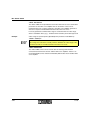
Please Observe the Following Notes:
In order to ensure the safe use of your device, we recommend that you read this
manual carefully. The following notes provide information on how to use this
manual.
User Group of This Manual
The use of products described in this manual is oriented exclusively to qualified
electricians or persons instructed by them, who are familiar with applicable national
standards. Phoenix Contact accepts no liability for erroneous handling or damage
to products from Phoenix Contact or third-party products resulting from disregard of
information contained in this manual.
Explanation of Symbols Used
The attention symbol refers to an operating procedure which, if not carefully
followed, could result in damage to hardware and software or personal injury.
The note symbol informs you of conditions that must strictly be observed to achieve
error-free operation. It also gives you tips and advice on the efficient use of
hardware and on software optimization to save you extra work.
The text symbol refers to detailed sources of information (manuals, data sheets,
literature, etc.) on the subject matter, product, etc. This text also provides helpful
information for the orientation in the manual.
We Are Interested in Your Opinion
We are constantly attempting to improve the quality of our manuals.
Should you have any suggestions or recommendations for improvement of the
contents and layout of our manuals, we would appreciate it if you would send us
your comments. Please use the universal fax form at the end of the manual for this.
694900
IB IL DC AR 48/10A
Statement of Legal Authority
This manual, including all illustrations contained herein, is copyright protected. Use
of this manual by any third party deviating from the copyright provision is forbidden.
Reproduction, translation, or electronic and photographic archiving or alteration
requires the express written consent of Phoenix Contact. Violators are liable for
damages.
Phoenix Contact reserves the right to make any technical changes that serve the
purpose of technical progress.
Phoenix Contact reserves all rights in the case of patent award or listing of a
registered design. Third-party products are always named without reference to
patent rights. The existence of such rights shall not be excluded.
Internet
Up-to-date information on Phoenix Contact products can be found on the Internet
at www.phoenixcontact.com.
694900
Table of Contents
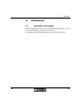
1
2
3
Fields of Application and Functions ......................................................................... 1-1
1.1
Short Description .................................................................................... 1-1
1.2
Possible Fields of Application................................................................. 1-1
1.3
Function.................................................................................................. 1-4
1.3.1
Speed Control Without IxR Compensation (Voltage Control) . 1-5
1.3.2
Speed Control With IxR Compensation .................................. 1-6
1.3.3
Torque Control (Current Control) ............................................ 1-6
1.3.4
Method of Operation of the Output Level ................................ 1-7
1.3.5
Operating Modes of the Output Level ..................................... 1-8
1.3.6
4 Quadrant Mode .................................................................... 1-9
1.3.7
Function of the Controller in the Device ................................ 1-12
Installing the Inline Servo Amplifier .......................................................................... 2-1
2.1
DRIVECOM Compatibility....................................................................... 2-1
2.2
Local LED Diagnostic and Status Indicators .......................................... 2-2
2.3
Mounting and Removing the Inline Servo Amplifier................................ 2-4
2.4
Connecting the Inline Servo Amplifier .................................................... 2-6
2.4.1
Terminal Assignment .............................................................. 2-6
2.4.2
Connecting the Power Supply ................................................ 2-7
2.4.3
Connecting the Motor ............................................................. 2-8
2.5
Calculating the Supply Voltage............................................................. 2-10
2.6
Selecting Compatible Motors................................................................ 2-10
Parameterization ...................................................................................................... 3-1
694900
3.1
Programming Data/Configuration Data .................................................. 3-1
3.2
Inline Servo Amplifier From the Point of View of the Fieldbus................ 3-2
3.3
Meaning of the Process Data Words.................................................... 3-12
3.3.1
IN Process Data Words ........................................................ 3-12
3.3.2
OUT Process Data Words .................................................... 3-12
3.3.3
Parameterizing the Inline Servo Amplifier
and Reading Information With PCP ...................................... 3-12
3.3.4
Parameterizing the Inline Servo Amplifier
via the PCP Channel ............................................................ 3-14
i
IB IL DC AR 48/10A
A
B
Parameters................................................................................................................A-1
A1
Structures of Functions...........................................................................A-1
A2
Parameter Lists ......................................................................................A-8
A 2.1
General Device Parameters ...................................................A-9
A 2.2
Additional Parameters in "Speed Specification" Mode .........A-21
A 2.3
Additional Parameters in "Torque Specification" Mode ........A-30
A 2.4
ParameterGroup1 (Index E000hex) .......................................A-33
A 2.5
Representation of Parameters by Their Indices ....................A-34
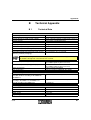
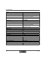
Technical Appendix...................................................................................................B-1
B1
Technical Data........................................................................................B-1
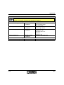
B2
Ordering Data .........................................................................................B-4
C
List of Figures........................................................................................................... C-1
D
List of Tables............................................................................................................ D-1
E
Index .........................................................................................................................E-1
ii
694900
Fields of Application and Functions
1
Fields of Application and Functions
This user manual is only valid in association with the IB IL SYS PRO UM E User
Manual or the Inline System Manual for your bus system.
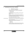
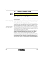
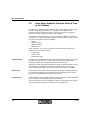
1.1
Short Description
The IB IL DC AR 48/10A Inline servo amplifier is a universal speed or torque
controller with a power output stage for permanently excited DC motors with
brushgears with a power consumption of up to 450 W.
The Inline servo amplifier has a 4 quadrant function, i.e., it supplies power back to
the power supply unit when the brake function is used (see page 1-11).
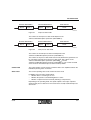
1.2
Possible Fields of Application
The Inline servo amplifier is used under the following conditions:
– Torque controller or speed controller
– Permanently excited DC motors with brushgears
– Nominal voltages of 12 V DC to 48 V DC
– Power consumption of up to 450 W
– Motor current of up to 10 A
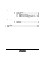
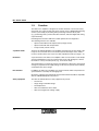
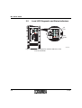
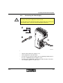
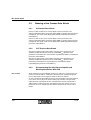
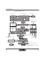
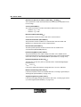
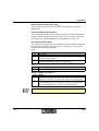
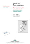
Typical Application
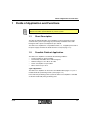
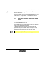
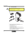
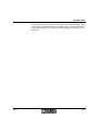
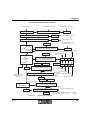
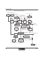
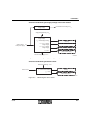
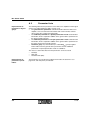
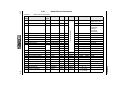
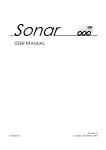
The Inline servo amplifier can be used as an individual drive (Figure 1-1) or in a
modular multi-axis positioning control system (Figure 1-2).
In the multi-axis positioning control system the Inline servo amplifier is controlled
via the IB IL POS 200 (-PAC) positioning CPU.
694900
1-1
IB IL DC AR 48/10A
R D
B A
S F
U L
U S
L D
R C
1
2
1
1
2
1
L 1
A 2
L 3
1
2
1
E 3
E 1
L 4
2
A 1
D
L 2
R U N
F A IL
U M
2
E 4
E 2
2
1
2
1
2
1
1 1
1 1
1 1
1 1
1 1
1 1
1 1
1
2
2 2
2 2
2 2
2 2
2 2
2 2
2 2
2
3
3 3
3 3
3 3
3 3
3 3
3 3
3 3
3
4
4 4
4 4
4 4
4 4
4 4
4 4
4 4
4
5
5 5
5
6
6 6
6
6 9 4 9 A 0 0 6
Figure 1-1
1-2
Use of the IB IL DC AR 48/10A as an individual drive
694900
Fields of Application and Functions
P o s itio n in g C P U
B A
R D
R C
L D
U L
A 1
D
U S
S F
A 2
2
2
2 4 V
1
2
U P
3
D N
5 V
Z
2 4 V
D
2
3
D N
5 V
Z
A x is 1 0
1
U P
3
D N
5 V
D
1
U P
3
Z
A x is 3
2 4 V
D
1
U P
D N
L 4
A x is 2
2 4 V
D
L 2
L 3
F A IL
E 4
E 2
L 1
R U N
E 3
E 1
U M
A x is 1
5 V
Z
IB IL P O S 2 0 0
1
2
1
2
1
2
1
1
2
2
1
2
1
2
1
1
2
2
1
2
1
2
1
2
1
2
1
2
1
2
1
2
1
2
1
1 1
1 1
1 1
1
1 1
1 1
1 1
1
1
1 1
1 1
1
1
1 1
1
1
1 1
1
1
1 1
1
2
2 2
2 2
2 2
2
2 2
2 2
2 2
2
2
2 2
2 2
2
2
2 2
2
2
2 2
2
2
2 2
2
3
3 3
3 3
3 3
3
3 3
3 3
3 3
3
3
3 3
3 3
3
3
3 3
3
3
3 3
3
3
3 3
3
4
4 4
4 4
4 4
4
4 4
4 4
4 4
4
4
44 4
4 4
4
4
4 4
4
4
4 4
4
4
4 4
4
P o s itio n d e te c tio n
L im it s w itc h
E n c o d e r
L im it s w itc h
D C
m o to r
6 9 4 9 A 0 3 7
Figure 1-2
694900
Use of the IB IL DC AR 48/10A in a modular multi-axis positioning
control system
1-3
IB IL DC AR 48/10A
1.3
Function
The Inline servo amplifier is designed as an Inline terminal. It can thus be easily
operated in any control system and can be used to create a distributed positioning
control system simply by mounting Inline positioning terminals side by side
(e.g., positioning CPUs, position detection terminals, and other digital and analog
output terminals).
LED diagnostic and status indicators enable quick local error diagnostics.
The following functions are available:
– Speed control without IxR compensation (voltage control)
– Speed control with IxR compensation
– Torque control (current control)
4 quadrant mode
The IB IL DC AR 48/10A Inline servo amplifier autonomously sets the speed or the
torque of the connected motor to the desired speed value/torque value, which it
receives via Inline in the form of process data (4 quadrant mode) (see page 1-11).
DC motors
A special feature of the Inline servo amplifier is that it can be used to create simple
speed-controlled drives using cost-effective DC motors with brushgears, without
the need for a rotary encoder system (e.g., on the motor shaft).
This method relies on a particular aspect of the behavior of DC motors: their speed
changes in proportion to the supply voltage. In this way the speed can be indirectly
controlled via the motor voltage.
IxR controller
In addition, the Inline servo amplifier uses an IxR controller, which compensates for
speed variations caused by the changing load.
Operation, setting the operating mode, and parameterization should be compatible
with the "DRIVECOM profile 22" protocol.
Safety equipment
1-4
The IB IL DC AR 48/10A uses safety equipment to prevent:
– Overcurrent
– Surge voltage and undervoltage
– Overtemperature
– Short circuit between motor cables
– Short circuit against the voltage supply
694900
Fields of Application and Functions
Voltage and current
supply
The IB IL DC AR 48/10A Inline servo amplifier is based on digital controllers. Its
task is to provide current and voltage values, which can be used to directly operate
DC motors with brushgears.
The level of the current and voltage values depends on the various functions, which
the Inline servo amplifier carries out in the individual operating modes. The power
supply of 12 V DC to 48 V DC and 0 A to 10 A is supplied to the Inline servo
amplifier via connection US.
1.3.1
Speed Control Without IxR Compensation (Voltage
Control)
In this function, the IB IL DC AR 48/10A Inline servo amplifier acts as a speed
controller (4 quadrant mode) without external feedback (e.g., tachometer signal)
(see also "4 Quadrant Mode" on page 1-9).
This method relies on a particular feature of DC motors, whereby the speed
increases in direct proportion to the motor voltage. The Inline servo amplifier only
controls the motor voltage (positive and negative).
If IxR compensation is not activated ("IxRCompensation" parameter = 0,
index 010Bhex), the Inline servo amplifier compares the actual motor voltage
(measured at the output terminals of the Inline servo amplifier) with the voltage that
is required for the desired speed and corrects it accordingly. The motor voltage and
speed are therefore not affected by fluctuations in the supply voltage.
Please note that the supply voltage for the Inline servo amplifier must be
approximately 10% higher than the voltage that it can supply to the motor.
694900
1-5
IB IL DC AR 48/10A
1.3.2
Speed Control With IxR Compensation
When the speed is controlled via the motor voltage, the speed changes in the event
of load fluctuations. The speed decreases at a constant motor voltage with
increasing load, as the ohmic resistors in the motors do not allow the current to
increase too high in proportion with the increasing load.
The Inline servo amplifier reduces these speed variations through the use of
"IxR compensation". This function increases the motor voltage in proportion to the
current increase, which is caused by the increasing load.
Total accuracy is limited due to the indirect speed control process. The extent to
which speed variations caused by load fluctuations can be limited depends on the
dynamic response of the load fluctuations and on the structure of the motor.
In general, load fluctuations can be reduced by up to 90% by activating IxR
compensation.
1.3.3
Torque Control (Current Control)
The IB IL DC AR 48/10A Inline servo amplifier uses this function to autonomously
set the torque of the connected motor to the desired torque value, which it receives
via Inline in the form of process data (4 quadrant mode, see page 1-9).
This is carried out using a current control, for which the Inline servo amplifier
provides feedback by measuring the motor current.
The torque control is used if the motor must produce a constant force, e.g., to wind
a spring or to supply a liquid at constant pressure.
With this function the drive behaves as follows: As long as the torque of the
mechanics is less than the torque with which the Inline servo amplifier operates the
drive, the drive speeds up (limited by the supply voltage). If the torque of the
mechanics is greater, the drive slows down.
The desired torque is specified as a per thousand value of the nominal torque. So
that the Inline servo amplifier can operate in this way, the nominal torque of the
motor (not residual) is loaded as an additional parameter.
1-6
694900
Fields of Application and Functions
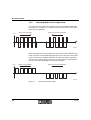
1.3.4
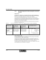
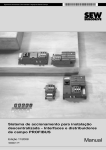
Pulse wide modulation
Method of Operation of the Output Level
The Inline servo amplifier generates the desired motor voltage or the desired motor
current (for torque control) using Pulse Wide Modulation (PWM).
The power supplied to the motor is switched. The mean motor voltage value is
controlled by the duration of the pulses.
U
M o to r
5 0
1 5 0
2 0 0
2 5 0
3 0 0
3 5 0
t [µ s ]
4 0 0
6 9 4 9 A 0 0 7
Figure 1-3
Pulse wide modulation (PWM)
The pulses are generated with a set frequency of 20 kHz.
694900
1-7
IB IL DC AR 48/10A
1.3.5
Operating Modes of the Output Level
The output level of the Inline servo amplifier operates with a bipolar PWM signal
(see Figure 1-4). A high level of efficiency can thus be achieved for motors with a
higher current requirement.
M o to r r u n s c lo c k w is e
U
M o to r r u n s c o u n te r c lo c k w is e
M o to r
t
6 4 5 5 A 0 0 8
Figure 1-4
4T mode (4 transistor mode)
When operating motors with low inductance and a small current requirement, this
mode can lead to an undesirably high temperature rise on the motor at low speeds.
In this case the motor should be switched to 2T mode, whereby the output level
operates with a unipolar signal (see Figure 1-5). Only positive or negative pulses
are sent to the motor depending on the direction of rotation.
U
M o to r
M o to r r u n s c lo c k w is e
M o to r r u n s c o u n te r c lo c k w is e
t
6 4 5 5 A 0 0 9
Figure 1-5
1-8
2T mode (2 transistor mode)
694900
Fields of Application and Functions
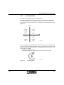
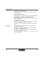
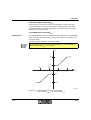
1.3.6
4 Quadrant Mode
The Inline servo amplifier supports 4 quadrant mode.
The name "4 quadrant mode" is derived from the representation of the possible
motor operating states in a speed/torque/coordinate system: The possible motor
torque and motor speed operating states are displayed in the four quadrants (see
Figure 1-6).
S p e e d n
II
I
n p o s itiv e
M n e g a tiv e
n p o s itiv e
M p o s itiv e
B ra k e d
c lo c k w is e
r o ta tio n
C lo c k w is e
r o ta tio n
M
C o u n te r
c lo c k w is e
r o ta tio n
B ra
c o u
c lo c k
ro ta
n n e g a tiv e
n e g a tiv e
n n e g a tiv e
M p o s itiv e
Figure 1-6
III
k e d
n te r
w is e
tio n
IV
T o rq u e M
6 4 5 5 A 0 1 0
Speed/torque/coordinate system
In counter clockwise and clockwise rotation, the torque operates in the direction of
speed, i.e., the motor is driven (quadrant I and III). In braked counter clockwise and
clockwise rotation, the torque operates in the opposite direction to speed, i.e., the
motor brakes are applied.
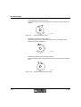
– Quadrant I: Clockwise rotation
Motor torque M operates in the direction of rotation of the motor shaft.
M
n
6 4 5 5 A 0 1 1
Figure 1-7
694900
Clockwise rotation
1-9
IB IL DC AR 48/10A
–
Quadrant II: Braked clockwise rotation
The torque operates in the opposite direction of rotation; the motor brakes are
applied.
n
M
6 4 5 5 A 0 1 2
Figure 1-8
–
Braked clockwise rotation
Quadrant III: Counter clockwise rotation
The torque operates in the direction of rotation; this is the opposite of the
direction of rotation in quadrant I.
n
M
6 4 5 5 A 0 1 3
Figure 1-9
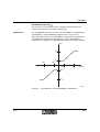
–
Counter clockwise rotation
Quadrant IV: Braked counter clockwise rotation
The torque operates in the opposite direction to the counter clockwise rotating
shaft.
n
M
6 4 5 5 A 0 1 4
Figure 1-10
1-10
Braked counter clockwise rotation
694900
Fields of Application and Functions
Regenerative Sequences
When the motor brakes are applied, the motor releases kinetic energy. In
4 quadrant mode, the generated kinetic energy is fed back into the intermediate
circuit of the power supply as electrical energy, i.e., at the power supply unit. If no
other devices (e.g., other Inline servo amplifiers) draw from this energy, the power
in the intermediate circuit can increase to a value, which can damage electrical
circuits or trigger a surge voltage shutdown in electronic power supply units.
As minor fluctuations are normal, the Inline servo amplifier and the power supply
unit must be able to withstand a higher power level than the maximum supplied by
the power supply unit. For the IB IL DC AR 48/10A this is 60 V.
The Inline servo amplifier has a voltage monitoring function, which switches off the
motor if the fixed voltage threshold is exceeded.
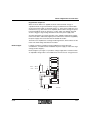
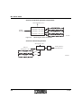
Brake chopper
If voltage overshoots caused by energy feedback have to be taken into
consideration, a module must be installed at the power supply to reduce the surge
voltage ("brake chopper").
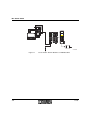
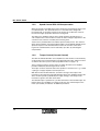
Brake choppers (1 in Figure 1-11) load the voltage supply with a resistance when
an adjustable voltage value is exceeded and convert the excess energy into heat.
+
1 2 V
0 A
1
4 8 V
1 0 A
_
+
_
6 9 4 9 A 0 3 8
Figure 1-11
694900
Connection diagram
1-11
IB IL DC AR 48/10A
1.3.7
Speed specification
Function of the Controller in the Device
In "Speed specification" mode two controllers are cascaded in the device:
– Speed controller
– Current controller
If a control parameter needs to be adjusted, both controllers must be
parameterized in this operating mode.
Torque specification
IxR compensation affects the speed controller. In "Torque specification" mode only
the current controller is active. If a control parameter needs to be adjusted, only the
current controller must be parameterized in this mode.
The controllers are set using standard parameters so that various applications can
be carried out without having to modify the parameterization.
The behavior of motors in machines greatly depends on the dynamic behavior of
the mechanics. If you observe irregular motor operation, adjust the control
parameters. Instructions on how to proceed are provided below.
Adjusting Control Parameters
Both controllers in the Inline servo amplifier (current controller and speed controller)
are PI controllers, i.e., proportional controllers with additional integral action. They
have no derivative action.
The default values of the control parameters are preselected in such a way that they
already provide good results in most applications. In special cases it may be
necessary to adjust the control parameters to the motor and drive used. To optimize
the control parameters, proceed as follows (see Section A, "Parameters"):
•
Enable operation (speed setpoint = 0).
•
Increase the KI value of the current controller as far as the stability limit.
•
Decrease the KI value of the current controller by 20%.
•
Increase the KP value of the current controller as far as the stability limit.
•
Decrease the KP value of the current controller by 20%.
•
Increase IxR compensation as far as the stability limit.
•
Decrease IxR compensation by 20%.
•
Increase the KI value of the speed controller as far as the stability limit.
•
Decrease the KI value of the speed controller by 20%.
•
Increase the KP value of the speed controller as far as the stability limit.
•
Decrease the KP value of the speed controller by 20%.
1-12
694900
Fields of Application and Functions
Optimization of the
control parameters
The dynamic properties of the drive for stable control behavior should already have
been further improved. In order to further optimize the control parameters, a jump
function for the desired speed may be useful.
It is advisable to record the speed behavior, e.g., using a tachometer generator and
an oscilloscope. Continue to vary the parameters for the speed controller until the
time curve of the speed actual value corresponds as closely as possible to the time
curve of the speed setpoint, whereby the control circuit must remain stable on each
load.
When using jump functions, observe the settings for the acceleration and braking
ramp as well as the value of the motor current limit.
694900
1-13
IB IL DC AR 48/10A
1-14
694900
Installing the Inline Servo Amplifier
2
Installing the Inline Servo Amplifier
2.1
DRIVECOM Compatibility
The IB IL DC AR 48/10A Inline servo amplifier has the same functions as
INTERBUS DRIVECOM profile 22. It therefore has two function groups:
– Speed function group
– Torque function group
The "ModeSelectionCode" parameter (index 6060hex) specifies which function
group should be active.
In addition, each parameter is assigned a special index (see "Parameters" on
page A-1).
The Inline servo amplifier is set to "Speed specification" mode by default. In this
operating mode, the speed setpoint is specified in revolutions per minute via
process data word 1 (or alternatively as a percentage, which can be converted into
a "speed setpoint" using the "speed reference value").
Once the speed setpoint has executed two factor functions, the speed and the
acceleration/delay are limited (see Figure A-1 on page A-2).
Per thousand function
The limited setpoint is then sent to the speed controller. As the controller operates
with per thousand values, all input and output values for the speed controller
execute a per thousand function.
In order to use per thousand functions, the Inline servo amplifier requires the
following motor reference values in the form of parameters:
– Nominal speed
– Nominal voltage
– Nominal current
The Inline servo amplifier uses a particular feature of DC motors for the speed
control function, whereby the speed responds in proportion to the motor voltage.
The speed controller indirectly controls the speed via the motor voltage.
694900
2-1
IB IL DC AR 48/10A
2.2
Local LED Diagnostic and Status Indicators
U S
IB
+
IB
U S
T R
-
U S
E R R
IB
+
T R
-
U S
+
-
T R
E R R
F E
U S
E R R
M O T O R
6 4 5 5 A 0 0 2
Figure 2-1
2-2
Local LED diagnostic and status indicators on the
IB IL DC AR 48/10A
694900
Installing the Inline Servo Amplifier
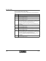
Table 2-1
Des.
IB
Meanings of the LED diagnostic and status indicators
Color
Meaning
Green LED
Diagnostics
ON
Bus active
Flashing
TR
US
ERR
0.5 Hz
Communications power present, bus not active
2 Hz
Communications power present, bus active, I/O error
4 Hz
Communications power present, terminal before the flashing module failed,
terminal behind the flashing module not part of the configuration frame
OFF
Communications power not present, bus not active
Green LED
PCP active
ON
PCP messages being transmitted to the Inline servo amplifier
OFF
No transmission of PCP messages
Green LED
Supply voltage of the power section (see Figure A-4 on page A-5)
ON
Supply voltage for the output stage is more than 75% of the nominal voltage of
the power supply
OFF
Supply voltage for the output stage is less than 75% of the nominal voltage of the
power supply
Red LED
Error (see Figure A-8 on page A-7)
ON
An error has occurred (corresponds to bit 3 in the status word)
OFF
No error
The cause of the error can be read in the "ErrorCode" parameter (index 603Fhex).
694900
2-3
IB IL DC AR 48/10A
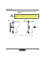
2.3
Mounting and Removing the Inline Servo
Amplifier
Do not replace terminals while the power is connected.
Before removing or mounting a terminal, disconnect the power to the entire
station. Make sure the entire station is reassembled before switching the power
back on.
A
A 1
B
B 1
A 2
B 2
B 1
A 1
6 9 4 9 A 0 3 9
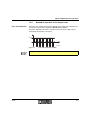
Figure 2-2
2-4
Mounting and removing the Inline servo amplifier
694900
Installing the Inline Servo Amplifier
Mounting the Inline Servo Amplifier (Figure 2-2, A)
•
•
Before snapping on the Inline servo amplifier, remove the adjacent connectors
of the next Inline terminal on the left.
Press the upper and lower snap-on mechanisms towards the center of the
module (A) and snap the module vertically onto the DIN rail (B).
Ensure that the featherkeys and keyways on the adjacent terminals are securely
interlocked.
Removing the Inline Servo Amplifier (Figure 2-2, B)
•
•
•
694900
Before removing the Inline servo amplifier, remove the adjacent connectors of
the neighboring Inline terminals (left and right).
Use a screwdriver to press the latches of the upper and lower snap-on
mechanisms outward (B1).
Remove the Inline servo amplifier from the DIN rail (B2).
2-5
IB IL DC AR 48/10A
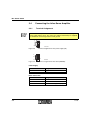
2.4
Connecting the Inline Servo Amplifier
2.4.1
Terminal Assignment
The Inline servo amplifier has two COMBICON connectors for connecting the
power supply and the motor. The connectors and the shield clamp are supplied
as standard for connecting functional earth ground.
1
+
-
2
Figure 2-3
6 4 5 5 A 0 0 3
Terminal assignment for the power supply (US)
1
+
2
F E
3
Figure 2-4
6 4 5 5 A 0 0 4
Terminal assignment for the motor (MOTOR)
Power Supply
Terminal Point
1
2
Assignment
US +
US –
Motor Connection
Terminal Point
1
2
3
2-6
Assignment
Motor +
Motor –
Functional earth ground (FE)
694900
Installing the Inline Servo Amplifier
2.4.2
Connecting the Power Supply
Observe the polarity.
The polarity of the power supply must not be reversed.
The entire motor circuit is designed for direct voltage polarity. Do not mix up the
plus and minus poles, as this can seriously damage the electronics.
A
2 0 m m
( 0 .7 9 in .)
1 0 m m
( 0 .3 9 in .)
B
C
6 9 4 9 A 0 4 0
Figure 2-5
•
•
•
•
694900
Connecting the power supply
Strip the cable and the wires (Figure 2-5, A).
Fit the stripped wire ends with ferrules.
Insert the wires for the power supply in the corresponding terminal points on
the 2-pos. COMBICON connector (Figure 2-5, B).
Insert the 2-pos. COMBICON connector in the upper slot (US) on the Inline
servo amplifier (Figure 2-5, C) and secure.
2-7
IB IL DC AR 48/10A
2.4.3
Connecting the Motor
Observe the polarity.
The polarity of the motor connections must not be reversed.
The motor must be connected via a two-wire shielded cable in order to prevent
errors during signal transmission.
A
3 1 m m
1 1 m m ( 1 .2 2 in .)
( 0 .4 3 in .)
1 0 m m
( 0 .3 9 in .)
BC
C
6 9 4 9 A 0 4 1
Figure 2-6
•
•
•
•
•
•
•
2-8
Connecting the motor
Strip the outer cable sheath off the cable (Figure 2-6, A).
Shorten the braided shield and place it around the outer cable sheath.
Remove the protective foil.
Fit the stripped wire ends with ferrules.
Fasten the shield clamp to the cable.
The shield clamp must be inserted in terminal point 3 on the connector.
It simultaneously provides strain relief.
Insert the wires for the motor connection in the corresponding terminal points
on the 3-pos. COMBICON connector (Figure 2-6, B).
Insert the 3-pos. COMBICON connector in the lower slot (MOTOR) on the
Inline servo amplifier (Figure 2-6, C) and secure.
694900
Installing the Inline Servo Amplifier
Notes on preventing errors
In order to prevent errors during signal transmission, please observe the
following:
•
Use a shielded cable to connect the Inline servo amplifier to the motor.
•
Ground the Inline servo amplifier by connecting the DIN rail on which it is
mounted to FE via the shortest possible route.
•
Install the data and signal cables separately from the supply line and the
motor connection cable.
•
Make sure the data and signal cables are as short as possible.
•
•
•
•
694900
Do not install the Inline servo amplifier until you are certain that the power
supply has been switched off for at least five minutes.
First, connect only the Inline servo amplifier to the power supply.
Do not connect the motor yet.
Set the desired parameters and operating modes.
Check whether the LEDs indicate normal operation (see "Local LED
Diagnostic and Status Indicators" on page 2-2).
If so, you can connect the motor.
2-9
IB IL DC AR 48/10A
2.5
Calculating the Supply Voltage
Please note that the supply voltage for the Inline servo amplifier must be
approximately 10% higher than the voltage that it can supply to the motor.
2.6
Selecting Compatible Motors
The Inline servo amplifier is designed for operating DC motors with brushgears with
permanent magnets.
Nominal voltage range
The nominal voltage range can be between 12 V DC and 48 V DC. The Inline servo
amplifier supplies a maximum of 10 A to the motor, i.e., a motor with a nominal
current of 3 A can start with a starting current of 10 A.
If you operate a motor with a nominal current of 10 A, it too only has a maximum
starting current of 10 A. The starting torque of the Inline servo amplifier is lower for
motors with a starting current of more than 10 A than for operation with a battery.
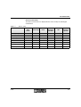
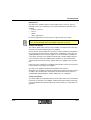
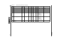
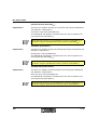
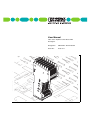
Temperature derating
of the motor current
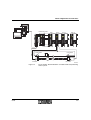
When operating larger machines at higher ambient temperatures, the temperature
derating of the motor current must be observed. Figure 2-7 on page 2-11 provides
information about the maximum available continuous motor current according to the
ambient temperature of the Inline servo amplifier.
The specified values are provided for reference only and vary according to the
installation space, the mounting position, and cooling air flow. The Inline servo
amplifier can temporarily supply motor currents of up to 10 A at any ambient
temperature. For larger motors in continuous operation at higher ambient
temperatures, the internal fan is activated in order to cool the Inline servo amplifier.
In the event of overtemperature (e.g., due to an overload) the power section of the
Inline servo amplifier switches off automatically and indicates the error "Output level
overtemperature" (see Figure A-6 on page A-6). The actual temperature of the
output level can be read from the "DeviceTemperature" parameter (index 6015hex).
2-10
694900
Installing the Inline Servo Amplifier
I/A
1 1
1 0
9
8
7
6
5
4
3
2
1
0
-3 0
Figure 2-7
-2 0
-1 0
0
1 0
2 0
3 0
4 0
5 0
6 0
7 0
T /° C
6 9 4 9 A 0 3 4
Working area of the Inline servo amplifier in open space
The connected motors should have a minimum inductance (see "Technical Data"
on page B-1). Motors with a lower inductance (motors with transformerless winding)
cannot smooth the switched motor voltage to a direct current. The AC component
then causes a temperature rise at the motor coils.
Minimum nominal
current
Motors operating on the Inline servo amplifier must have a minimum nominal
current. If this value is not reached, the effectiveness of current detection is limited,
and therefore also the effectiveness of the current controller.
In particular, in "Torque specification" mode the motor should have a nominal
current of more than 100 mA. Smaller motors with a lower nominal current can also
be operated in "Speed specification" mode but speed accuracy is limited.
694900
2-11
IB IL DC AR 48/10A
2-12
694900
Parameterization
3
Parameterization
3.1
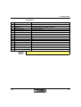
Programming Data/Configuration Data
INTERBUS
ID code
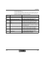
C3hex (195dec)
Length code
02hex (02dec)
Process data channel
32 bits
Input address area
2 words
Output address area
2 words
Parameter channel (PCP)
1 word
Register length (bus)
3 words
Other Bus Systems
For the configuration data of other bus systems, please refer to the corresponding
electronic device data sheet (GSD, EDS) at www.phoenixcontact.com.
694900
3-1
IB IL DC AR 48/10A
3.2
Inline Servo Amplifier From the Point of View
of the Fieldbus
The Inline servo amplifier provides digital access to all the drive parameters and
functions via the local bus interface, i.e., the Inline servo amplifier is only
parameterized and controlled via the bus. There are no option for setting the
resistance or other settings on the Inline servo amplifier.
The amplifier is controlled via fast, cyclic process data. In addition to specifying
setpoints (e.g., desired speed value), this process data channel can also be used
to execute various drive functions including:
– Enable
– Enable operation
– Disable operation
– Quick stop, etc.
At the same time, you can also read back actual values from the Inline servo
amplifier via this channel, including:
– Actual speed
– Actual current
– Actual device state
Communication
The Inline servo amplifier communicates with the higher-level control system via the
local bus as well as via the fast, cyclic process data channel and the acyclic
parameter channel (PCP, Peripherals Communication Protocol).
While process data is generally exchanged cyclically, the drive parameters can be
read and written acyclically via the "Read" and "Write" PCP services. These
services do not permanently store the parameters in the Inline servo amplifier.
Process data
Process data is time-critical status information that changes continually and must
be continuously updated. This information must be transmitted at short regular
intervals. It is transmitted via the process data channel.
Parameter data
Parameter data is data that seldom changes and must therefore only be transmitted
when required. It is transmitted via PCP communication.
In the bus ring, the Inline servo amplifier occupies one word for the PCP channel
and two process data words (not variable) for each data direction.
3-2
694900
Parameterization
P ro c e s s d a ta w o rd 0
B y te 0
B y te 1
S ta tu s w o rd
P ro c e s s d a ta w o rd 1
B y te 2
B y te 3
P C P c h a n n e l
1 6 b its
A c tu a l v a lu e
Figure 3-1
6 9 4 9 A 0 1 6
IN process data words
The contents of the IN process data words depend on the
"INProcessDataDescription" parameter (index 6000hex).
P ro c e s s d a ta w o rd 0
B y te 0
B y te 1
C o n tro l w o rd
Figure 3-2
P ro c e s s d a ta w o rd 1
B y te 2
B y te 3
P C P c h a n n e l
1 6 b its
S e tp o in t
6 9 4 9 A 0 1 7
OUT process data words
The contents of the OUT process data words depend on the
"OUTProcessDataDescription" parameter (index 6001hex).
The contents of the process data words can be freely defined. Any parameter can
be selected for transmission in the process data word. This is done via the
"INProcessDataDescription" parameter (index 6000hex) and the
"OUTProcessDataDescription" parameter (index 6001hex). The control word and
status word are transmitted in process data word 0 by default.
Control word
The control word is used to remotely control the Inline servo amplifier between the
individual operating states via the bus.
Status word
The current operating state can be read in the status word.
In addition, bits in the status word indicate:
– Whether there is a warning or an error
– Whether the speed or current limiting device is active
– Whether a setpoint has been reached (following a ramp function)
Depending on the operating mode, the speed setpoint or the torque setpoint is
written to OUT process data word 1. An actual value is usually read from IN process
data word 1.
694900
3-3
IB IL DC AR 48/10A
PCP channel
All the parameters for the individual functions are written to or read from the PCP
channel via specific indices. As parameter data seldom changes, it is sent via the
PCP channel on which messages are only transmitted when required. Data is
transmitted via PCP communication, whereby a message is sent and its index
determines which parameter is addressed. For every parameter an access attribute
specifies whether the parameter can be read or written.
Control via the Control Word/Status Word
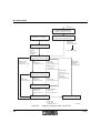
The control word is used to change the operating state of the Inline servo amplifier
via the bus. Figure 3-3 on page 3-8 illustrates this "remote control" sequence. The
different operating states can only be reached in a specific sequence.
Once switched on, the device must first pass through the "Not ready to operate",
"Start inhibit", "Ready to operate", and "ON" states to enter the "Operation enabled"
state.
The next operating state is reached by setting/resetting the relevant bits in the
control word. The Inline servo amplifier continuously indicates its operating state in
the control word.
3-4
694900
Parameterization
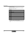
Control Word
Bit
0
1
2
3
4
5
6
7
8
9
10
11
12
13
14
15
Assignment
Switch on
Disable voltage
Quick stop
Enable operation
–
–
–
Reset error
–
–
–
Activate LowRuntime2
–
–
–
–
Remark
Switch on the power section
Voltage is switched off, active low
Execute the quick stop function, active low
Enable drive function
0
0
0
Reset errors whose causes have been removed (see status word, bit 3)
0
0
0
Activate LowRuntime2 instead of LowRuntime
0
0
0
0
All states are active high unless otherwise stated.
694900
3-5
IB IL DC AR 48/10A
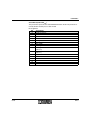
Status Word
Bit
0
1
2
3
4
5
6
7
Assignment
Ready to operate
ON
Operation enabled
Error
Voltage disabled
Quick stop
Start inhibit
Warning
8
9
10
Message
Remote
Setpoint reached
11
Limit value
See "WarningCode" parameter (index 010Dhex) on page A-13
0
1 (parameters can be modified)
Defined setpoint (at the ramp generator output) has been reached
(ramp has ended)
"Speed specification" mode: speed limit active or current limit active
12
13
14
15
–
–
–
–
"Torque specification" mode: current limit is active
0
0
0
0
3-6
Remark
See "Device Control States" on page 3-7
Warning present
694900
Parameterization
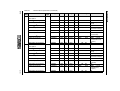
Device Control States
The device control states are displayed in the status word by the following bit
combinations:
Table 3-1
Device states
State
Bit 6
Start
Inhibit
Bit 5
Quick Stop
Bit 3
Error
Bit 2
Operation
Enabled
Bit 1
ON
Bit 0
Ready to
Operate
Not ready to operate
0
X
0
0
0
0
Start inhibit
1
X
0
0
0
0
Ready to operate
0
1
0
0
0
1
ON
0
1
0
0
1
1
Operation enabled
0
1
0
1
1
1
Error
0
X
1
0
0
0
Error response active
0
X
1
1
1
1
Quick stop active
0
0
0
1
1
1
694900
3-7
IB IL DC AR 48/10A
1 3
E v e n t e rro r
E r r o r r e s p o n s e a c tiv e
S ta tu s w o rd x x x x x x x x x x x x 1 x x x
C o n n e c t U
S
, U
L
a n d U
E rro r
M
S ta tu s w o rd x x x x x x x x x x x x 1 0 0 0
1 4
R e s e t e rro r
c o n tro l w o rd :
x x x x x x x x 0 x x x x x x x
N o t re a d y to o p e ra te
S ta tu s w o rd x x x x x x x x 0 0 0 0 0 0 0 0
A u to
w h e
in itia
c o m
m a tic
x x x x x x x x 1 x x x x x x x
n
liz a tio n is
p le te
S ta r t in h ib it
S ta tu s w o rd x x x x x x x x x 1 x x 0 0 0 0
9
2
7
D is a b le v o lta g e
c o n tro l w o rd :
x x x x x x x x x x x x x x 0 x
S to p
c o n tro l w o rd :
x x x x x x x x x x x x x 1 1 0
Q u ic k s
c o n tro l
x x x x x x
o r
D is a b le
c o n tro l
x x x x x x
1 2
A u
c h
e n
q u
to p
w o rd :
x x x x x x x 0 1 x
v o lta g e
w o rd :
x x x x x x x x 0 x
R e a d y to o p e ra te
S ta tu s w o rd x x x x x x x x x 0 1 0 0 0 0 1
8
3
6
S to p
c o n tro l w o rd :
x x x x x x x x x x x x x 1 1 0
S w itc h o n
c o n tro l w o rd :
x x x x x x x x x x x x x 1 1 1
S to p
c o n tro l w o rd :
x x x x x x x x x x x x x 1 1 0
to m
a n g
d o
ic k
a tic a lly
e s a t th e
f th e
s to p ra m p
1 0
D is a b le
c o n tro l
x x x x x x
o r
Q u ic k s
c o n tro l
x x x x x x
v o lta g e
w o rd :
x x x x x x x x 0 x
to p
w o rd :
x x x x x x x 0 1 x
O N
S ta tu s w o rd x x x x x x x x x 0 1 0 0 0 1 1
4
5
E n a b le o p e r a tio n
c o n tro l w o rd :
x x x x x x x x x x x x 1 1 1 1
D is a b le o p e r a tio n
c o n tro l w o rd :
x x x x x x x x x x x x 0 1 1 1
O p e r a tio n e n a b le d
Q u ic k s to p a c tiv e
S ta tu s w o rd x x x x x x x x x 0 1 0 0 1 1 1
S ta tu s w o rd x x x x x x x x x 0 0 x 0 1 1 1
1 1
Q u ic k s to p
c o n tro l w o rd :
x x x x x x x x x x x x x 0 1 x
Figure 3-3
3-8
6 9 4 9 A 0 1 8
Diagram showing the device control states
694900
Parameterization
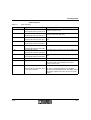
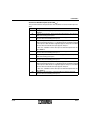
Table 3-2
Device control states
State/Status
Not ready to operate
Description
In this state, the Inline servo amplifier has just been connected to the
supply voltages US, UL, and UM.
The Inline servo amplifier is not able to accept control commands from the
bus yet.
–
–
–
–
Start inhibit
The self-test is running.
Initialization is still running.
The power level is disabled.
The drive is disabled.
When initialization is complete, the Inline servo amplifier automatically
switches to the "Start inhibit" state.
In this state:
–
–
Ready to operate
The software and hardware initialization is complete.
The parameterization of the functions with stored values (default
values) is complete.
– All functions can be parameterized.
– The drive is disabled.
– The power level is disabled.
– Activation of the power level and controller functions is disabled.
In this state:
ON
– The functions can be parameterized.
– The drive is disabled.
– The power level is disabled.
In this state:
Operation enabled
– The functions can be parameterized.
– The drive is disabled.
– The power level is disabled.
In this state:
–
–
–
–
694900
Operation is enabled.
The power level and controller functions are activated.
The speed setpoint (or torque setpoint) is processed (the
motor can run).
The functions can be parameterized.
3-9
IB IL DC AR 48/10A
Table 3-2
Device control states (Continued)
State/Status
Quick stop active
Description
In this state:
–
Error response active
Error
The "quick stop" command was initiated in the "Operation enabled"
state.
– The drive is slowed down by the quick stop ramp (according to the
"SpeedQuickStop" parameter (index 604Ahex) or the "QuickStopTime"
parameter (index 6051hex)).
– The device automatically switches to the "Start inhibit" state at the end
of the quick stop ramp.
An error occurred and the error response was initiated: the power level is
disabled. At the same time, the "ERR" LED lights up and the "Error" bit is
set in the control word.
The power level is disabled.
The cause of the error can be determined and the error removed in the
"Error" state ("ErrorCode" parameter (index 603Fhex)). The device exits the
state with the "Reset error" command (see "State Transitions" on
page 3-11).
3-10
694900
Parameterization
State Transitions
Table 3-3
State transitions
State Transition
2, 6, 8
Trigger
Command: Stop
Description
Command for the transition from various states to the
"Ready to operate" state.
5
Control word: xxxx xxxx xxxx x110
Command: Switch on
Command for the transition from the "Ready to
operate" state to the "ON" state.
Control word: xxxx xxxx xxxx x111
Command: Enable operation
Command for the transition to the "Operation enabled"
state.
Control word: xxxx xxxx xxxx 1111
Command: Disable operation
Command for the transition to the "ON" state.
7, 9, 10
Control word: xxxx xxxx xxxx 0111
Command: Disable voltage
Command for the transition to the "Start inhibit" state.
7, 10
Control word: xxxx xxxx xxxx xx0x
Command: Quick stop
Command for the transition to the "Start inhibit" state.
3
4
11
12
13
14
Control word: xxxx xxxx xxxx x01x
Command: Quick stop
Command for the transition to the "Quick stop active"
state.
Control word: xxxx xxxx xxxx x01x
End of the "Quick stop active" state The transition is automatic.
Event: Error
An error was detected by the drive controller.
Command: Reset error
The event results in the transition to the "Error
response active" state.
Command to acknowledge an error.
Control word: xxxx xxxx 0xxx xxxx If no error is detected, the Inline servo amplifier
xxxx xxxx 1xxx xxxx
switches to the "Start inhibit" state. The "ERR" LED is
switched off and the "Error" bit in the status word is
deleted.
694900
3-11
IB IL DC AR 48/10A
3.3
3.3.1
Meaning of the Process Data Words
IN Process Data Words
IN process data word 0 can be used to display various parameters. The
"INProcessDataDescription" parameter (index 6000hex) specifies which parameter
is displayed. The status word is displayed by default ("StatusWord" parameter,
index 6041hex).
IN process data word 1 can be used to display various parameters. The
"INProcessDataDescription" parameter (index 6000hex) specifies which parameter
is displayed. The speed actual value is displayed by default ("SpeedActualValue"
parameter, index 6044hex).
3.3.2
OUT Process Data Words
OUT process data word 0 can be used to transmit various parameters. The
"OUTProcessDataDescription" parameter (index 6001hex) specifies which
parameter is transmitted. The control word is transmitted by default ("ControlWord"
parameter, index 6040hex).
OUT process data word 1 can be used to transmit various parameters. The
"OUTProcessDataDescription" parameter (index 6001hex) specifies which
parameter is transmitted. The speed setpoint is transmitted by default
("SpeedSetpoint" parameter, index 6042hex).
3.3.3
PCP channel
Parameterizing the Inline Servo Amplifier and
Reading Information With PCP
All the parameters for the individual functions are written to or read from the PCP
channel via specific indices. Parameters which have been specified using OUT
process data words can no longer be written via the PCP channel.
As a lot of parameter data seldom changes or the information is often only required
once, data is sent via the PCP channel, which only transmits messages when
required. Data is transmitted via PCP communication, whereby a parameter is
addressed by an index and is then transmitted via the PCP channel. For every
parameter an access attribute specifies whether the parameter can be read or
written.
3-12
694900
Parameterization
To minimize the number of PCP messages, which must be sent by the higher-level
control system to initialize the Inline servo amplifier, the most important parameters
are grouped together in "ParameterGroup1" (index E000hex) (see Section A 2.4 on
page A-33).
694900
3-13
IB IL DC AR 48/10A
3.3.4
Parameterizing the Inline Servo Amplifier via the PCP
Channel
PMS Interface
The Inline servo amplifier has a standard PMS interface (Peripherals Message
Specification) according to DIN 19245-T2. This communication channel provides
full access to all the drive parameters of the Inline servo amplifier.
The communication relationship list (CRL) is based on PCP communication.
Following power up, it specifies the communication reference (CR) under which a
PCP device (e.g., the IB IL DC AR 48/10A) was found by the master and which
PMS services this PCP device supports.
Each line in the CRL contains comprehensive information about the connection
parameters as well as the CR.
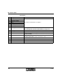
Table 3-4
Connection parameters of the Inline servo amplifier (using the example of INTERBUS)
Communication
Reference (CR)
Connection Parameters of the Inline Servo Amplifier
Size of the Low
Priority Transmit
Buffer
Size of the Low
Priority Receive
Buffer
Supported PMS Services
Automatically
determined by the
INTERBUS
controller
board, e.g., 2, 3, 4,
etc.
40hex
40hex
0 0 0 0
(Maximum length of a
PDU in the transmit
direction: 64 bytes)
(Maximum length of a
PDU in the receive
direction: 64 bytes)
h e x
0 0 0 0
h e x
3 0 0 0
h e x
A s S e rv e r
"R e a d " a n d
" W r ite "
A s c lie n t n o s e r v ic e
S u p p o r te d s e r v ic e s
Object Dictionary (OD)
In order to distinguish between the individual parameters during communication,
each parameter has a unique number (index).
The index is listed together with the description of the parameter features in a
standardized list, the object dictionary (OD). Each PCP device, which exchanges
information via the parameter data channel, has its own object dictionary.
The object dictionary is not implemented in the Inline servo amplifier. Please refer
to the information in the "Parameters" on page A-1.
3-14
694900
Parameterization
PMS Services
The Inline servo amplifier supports several PMS services. However, only the
following services are of importance for the parameterization of the Inline servo
amplifier:
– "Initiate" (connect)
– "Read"
– "Write"
– "Abort" (disconnect)
No further explanations of other services are given in this user manual.
Additional information can be found in the "Peripherals Communications Protocol
(PCP)" User Manual IBS SYS PCP G4 UM E, Order-No. 27 45 16 9.
"Initiate" PCP Service
The "Initiate" PMS service can be used to establish a communication connection
between a bus master and the Inline servo amplifier.
The bus master always initiates the connection. Various conditions with regard to
the communication connection are checked when establishing a connection, e.g.,
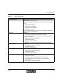
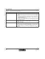
supported PMS services, user data length, etc. If the connection is established
successfully, the Inline servo amplifier responds with a positive initiate response.
If the connection cannot be established, the conditions for the communication
connection between the bus master and the Inline servo amplifier have not been
met.
If this is the case, compare the configured communication reference list of the bus
master with that of the Inline servo amplifier.
The Inline servo amplifier responds with an initiate error response.
Attempting to re-establish an existing communication connection usually results in
an "Abort". The communication connection is then aborted and can only be reestablished by implementing the "Initiate" PMS service for a third time.
"Read" PCP Service
The "Read" PMS service provides the bus master with read access to all the drive
parameters of the Inline servo amplifier. All drive parameters and their meanings
are listed in detail in the parameter directory in this manual (see "Parameters" on
page A-1).
694900
3-15
IB IL DC AR 48/10A
"Write" PCP Service
The "Write" PMS service provides the bus master with write access to all the drive
parameters of the Inline servo amplifier that can be written. In the event of
unauthorized access to a drive parameter, the Inline servo amplifier generates a
write error response with detailed information about the error cause.
For many parameters a limited value range is used rather than the value range,
which is available in theory (e.g., -32768 to 32767 for INT16) for the data type used.
Example
Value range for speed setpoint ("SpeedSetpoint" parameter, index 6042hex):
-30000 to 30000 rpm
If a write service is sent with a value outside its value range, but within the INT16
value range, the value that is actually written is limited to the value range of the
parameter, but this is not indicated and an error does not occur.
"Abort" PCP Service
The "Abort" PMS service can be used to abort an existing communication
connection between the bus master and the Inline servo amplifier. "Abort" is an
unconfirmed PMS service and can be initiated by both the bus master and the Inline
servo amplifier.
3-16
694900
Parameters
A
A1
Parameters
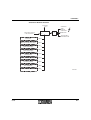
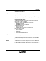
Structures of Functions
The following diagrams show the structure of the speed and control function, as well
as the various monitoring, warning, and error functions.
They describe how the individual parameters are used within the functions.
694900
A-1
IB IL DC AR 48/10A
Structure of the Speed Function
S p e e d S e tp o in t
v
6 0 4 2
P e r c e n ta g e S e tp o in t 6 0 5 2
h e x
S p e e d R e fe r e n c e V a lu e
h e x
1 /p e r c e n ta g e fu n c tio n
0
F a c to r fu n c tio n
D
F a c to r fu n c tio n
v
fa c to r
R e fe re n c e
S e tp o in tF a c to r 6 0 4 B
v
A c c e le r a tio n
lim its ,
ra m p s
6 0 4 8
fa c to r
S fa c to r
a
B
m a x
6 0 4 A
h e x
a
V
a
V 2
S
B e z u g
tH
n ..
/v
h e x
a
v
D
m in
h e x
S p e e d A c c e le r a tio n
fa c to r
F a c to r fu n c tio n
A c tiv e = 0
h e x
S p e e d Q u ic k S to p
S p e e d D e la y 6 0 4 9 hex
" L im it v a lu e " b it in th e s ta tu s w o r d ( b it 1 1 )
D
h e x
S p e e d M in M a x V a lu e 6 0 4 6
S p e e d M in M a x 6 0 4 7 hex
fa c to r
F a c to r fu n c tio n
S p e e d lim it
A c tiv e = 1
h e x
D im e n s io n F a c to r 6 0 4 C
S fa c to r
D
6 0 4 E
tT
tT
tS
2
1 /fa c to r fu n c tio n
S p e e d R e fe re n c e V a r ia b le 6 0 4 3 hex
P e r c e n ta g e fu n c tio n
6 0 5 3
" S e tp o in t r e a c h e d " b it
in th e s ta tu s w o r d
( b it 1 0 )
v
H ig h R u n tim e 6 0 4 F
P e rc e n ta g e R e fe r e n c e V a r ia b le
h e x
L o w R u n tim e 6 0 5 0
h e x
h e x
L o w R u n tim e 2 * 0 1 2 0
h e x
R e fe re n c e
Q u ic k S to p T im e
D
fa c to r
6 0 5 1
h e x
S fa c to r
S p e e d A c tu a lV a lu e
C o n tr o l fu n c tio n
( s e e F ig u r e A - 3 )
6 0 4 4
h e x
1 /fa c to r fu n c tio n
S p e e d A c tu a lV a lu e
P e r c e n ta g e fu n c tio n
M o to r
v
Figure A-1
A-2
R e fe re n c e
6 0 4 4
h e x
P e r c e n ta g e A c tu a lV a lu e
6 0 5 4
h e x
* T h e " A c tiv a te L o w R u n tim e 2 " b it in th e c o n tr o l w o r d
( b it 1 1 ) s w itc h e s b e tw e e n a V a n d a V 2
6 9 4 9 A 0 1 9
Speed function
694900
Parameters
Structure of the Speed Function in Detail
S p e e d S e tp o in t
v
X = v
0
6 0 4 2
P e r c e n ta g e S e tp o in t 6 0 5 2
h e x
v
0
= v
0
* p e r c e n ta g e s e tp o in t/1 6 3 8 3
R e fe re n c e
* n u m e r a to r ( D fa c to r ) /d e n o m in a to r ( D
fa c to r)
D
Y = X * n u m e r a to r ( S fa c to r ) /d e n o m in a to r ( S fa c to r )
D
n
n
S p e e d lim it
A c tiv e = 1
m in
= v
m in
m a x
= v
m a x
S p e e d R e fe r e n c e V a lu e
h e x
fa c to r
A c tiv e = 0
D
B
* N
(D
V
* N
(D
S
* N
(D
fa c to r
fa c to r
v
fa c to r)/D
fa c to r)/D
fa c to r)/D
a
v
v
* 1 6 3 8 3 /V
H ig h R u n tim e 6 0 4 F
R e fe re n c e
a
B
tH
R e fe re n c e
S p e e d R e fe re n c e V a r ia b le 6 0 4 3 hex
" S e tp o in t r e a c h e d " b it
in th e s ta tu s w o r d
( b it 1 0 )
/v
m a x
6 0 4 A
h e x
h e x
(D fa c to r)
(D fa c to r)
(D fa c to r)
V = X /(N (D fa c to r)/D (D fa c to r))
* 1 /(N (S fa c to r)/D (S fa c to r))
0
m in
h e x
S p e e d A c c e le r a tio n
S fa c to r
P e r c e n ta g e r e fe r e n c e v a r ia b le = v
h e x
S p e e d Q u ic k S to p
S p e e d D e la y 6 0 4 9 hex
6 0 4 8
a B´= a
a B´= a
a S´= a
h e x
S p e e d M in M a x V a lu e 6 0 4 6
S p e e d M in M a x 6 0 4 7 hex
fa c to r
* N (D fa c to r)/D (D fa c to r)
* N (D fa c to r)/D (D fa c to r)
D
n ..
S e tp o in tF a c to r 6 0 4 B
S fa c to r
h e x
R e fe re n c e
D im e n s io n F a c to r 6 0 4 C
" L im it v a lu e " b it in th e s ta tu s w o r d ( b it 1 1 )
A c c e le r a tio n
lim its ,
ra m p s
v
6 0 4 E
a
V
tT
V 2
tT
2
a
S
tS
h e x
L o w R u n tim e 6 0 5 0
h e x
P e rc e n ta g e R e fe r e n c e - L o w R u n tim e 2 * 0 1 2 0 hex
V a r ia b le
Q u ic k S to p T im e 6 0 5 1
6 0 5 3 hex
h e x
R e fe re n c e
D
fa c to r
S fa c to r
S p e e d A c tu a lV a lu e
C o n tr o l fu n c tio n
( s e e F ig u r e A - 3 )
6 0 4 4
h e x
V = X /(N (D fa c to r)/D (D fa c to r))
* 1 /(N (S fa c to r)/D (S fa c to r))
S p e e d A c tu a lV a lu e
M o to r
P e r c e n ta g e a c tu a l v a lu e = v
v
Figure A-2
694900
0
* 1 6 3 8 3 /v
R e fe re n c e
R e fe re n c e
6 0 4 4
h e x
P e r c e n ta g e A c tu a lV a lu e
6 0 5 4
h e x
* T h e " A c tiv a te L o w R u n tim e 2 " b it in th e c o n tr o l w o r d
( b it 1 1 ) s w itc h e s b e tw e e n a V a n d a V 2
6 4 5 5 A 0 2 0
Speed function in detail
A-3
IB IL DC AR 48/10A
Structure of the Control Function
S p e e d R e fe r e n c e V a r ia b le 6 0 4 3
h e x
T o r q u e S e tp o in tE x te r n a l 6 0 7 1
h e x
O u tp u tL e v e lM o d e 0 1 2 1
P e r th o u s a n d
fu n c tio n
N o m in a l
s p e e d
6 0 6 0
K P S p e e d C o n tr o lle r 0 1 0 9
h e x
T o r q u e M a x V a lu e
C u r r e n tM a x V a lu e 6 0 7 3 hex
h e x
C u r r e n tM in M a x V a lu e 0 1 0 6 hex
R e q u e s t
o p e r a tin g m o d e
K lS p e e d C o n tr o lle r
0 1 0 A
4
T o rq u e /
c u rre n t
lim it
2
Iso
0
ll
6 0 7 2
h e x
2 T m o d e /
4 T m o d e
K P C u r r e n tC o n tr o lle r
0 1 0 7
T o rq u e R e fe re n c e V a r ia b le 6 0 7 4
h e x
S p e e d
c o n tr o lle r
h e x
M o d e S e le c tio n C o d e
h e x
K lC u r r e n tC o n tr o lle r
0 1 0 8
h e x
h e x
O u tp u t s ta g e
Io
C u rre n t
c o n tr o lle r
u t
A c tiv e = 1
" L im it v a lu e "
b it in th e
s ta tu s w o r d ( b it1 1 )
D is p la y
c u rre n t m o d e
M o d e D is p la y
6 0 6 1
M o n ito r s u p p ly v o lta g e
o f th e p o w e r s e c tio n
( s e e F ig u r e A - 4 )
h e x
C u r r e n tA c tu a lV a lu e 6 0 7 8
T o r q u e A c tu a lV a lu e 6 0 7 7 hex
Ix R
c o m p e n s a tio n
h e x
In te r m e d ia te C ir c u itV o lta g e
6 0 7 9
Ix R C o m p e n s a tio n
0 1 0 B
M o n ito r
d e v ic e
te m p e ra tu re
( s e e F ig u r e A - 6 )
h e x
h e x
N o m in a lC u r r e n tM o to r 0 1 0 4 hex
P e r th o u s a n d fu n c tio n
D e v ic e T e m p e ra tu re
6 0 1 5
S p e e d A c tu a lV a lu e
h e x
6 0 4 4
1 /p e r th o u s a n d
fu n c tio n
M o n ito r
m o to r c u rre n t
( s e e F ig u r e A - 5 )
N o m in a l s p e e d
N o m in a lS p e e d M o to r 0 1 0 C
h e x
D e te c t
m o to r c u rre n t
D e te c t
m o to r v o lta g e
P e r th o u s a n d
fu n c tio n
N o m in a lV o lta g e M o to r 0 1 0 0
h e x
h e x
M o to r V o lta g e A c tu a lV a lu e
0 1 0 5
h e x
M o to r
6 9 4 9 A 0 2 1
Figure A-3
A-4
Control function
694900
Parameters
Structure for Monitoring the Supply Voltage of the Power Section
D e te c t
s u p p ly v o lta g e
In te r m e d ia te C ir c u itV o lta g e 6 0 7 9
S u p p ly V o lta g e W a r n in g 0 1 0 3
h e x
h e x
M o n ito r
s u p p ly v o lta g e
U
S
U
S u p p ly v o lta g e
o f th e p o w e r s u p p ly
S
U s
U
S
> 0 .7 5 * n o m in a l
v o lta g e s u p p ly
"U S " L E D
< 0 .7 5 * n o m in a l
v o lta g e s u p p ly
E r r o r : U n d e r v o lta g e o f th e
p o w e r s e c tio n s u p p ly
U
S
E r r o r : S u r g e v o lta g e o f th e
p o w e r s e c tio n s u p p ly
> 6 0 V
N o m in a lV o lta g e S u p p ly 0 1 0 1
Figure A-4
U n d e r v o lta g e
w a r n in g
< u n d e r v o lta g e w a r n in g
h e x
6 9 4 9 A 0 2 3
Monitoring the supply voltage of the power section
Structure for Monitoring the Motor Current
M o to r C u r r e n tW a r n in g
0 1 0 2
h e x
M o n ito r m o to r c u r r e n t
IM > m o to r c u r r e n t w a r n in g
M o to r c u rre n t
IM > 1 5 0 A
O v e rc u rre n t
w a r n in g
s
E r r o r : S h o r t c ir c u it
a t th e m o to r o u tp u t
6 9 4 9 A 0 2 4
Figure A-5
694900
Monitoring the motor current
A-5
IB IL DC AR 48/10A
Structure for Monitoring the Device Temperature
D e v ic e T e m p e r a tu r e
6 0 1 5
h e x
M e a s u re te m p e ra tu re
E r r o r : O u tp u t le v e l
o v e rte m p e ra tu re
T e m p e ra tu re > 8 5 ° C (1 8 5 ° F )
H e a ts in k
te m p e ra tu re
A c tiv a te
in te r n a l fa n
T e m p e ra tu re > 7 5 ° C (1 6 7 ° F )
T e m p e ra tu re < 6 5 ° C (1 4 9 ° F )
Figure A-6
D e a c tiv a te
in te r n a l fa n
6 9 4 9 A 0 2 5
Monitoring the device temperature
Structure of the Warning Function
W a r n in g C o d e
0 1 0 D
W a r n in g c o d e
W r ite 0 to
W a r n in g C o d e 0 1 0 D
R e s e t
> 0
" W a r n in g " b it ( b it 7 )
in th e s ta tu s w o r d
h e x
U n d e r v o lta g e
w a r n in g
0 0 0 2
h e x
O v e rc u rre n t
w a r n in g
0 0 0 1
h e x
Figure A-7
A-6
h e x
6 9 4 9 A 0 2 2
Warnings
694900
Parameters
Structure of the Error Function
E rro rC o d e
6 0 3 F
E rro r c o d e
" R e s e t e r r o r " b it ( b it 7 )
in th e c o n tr o l w o r d
A c tiv a te th e
"E rro r
re s p o n s e
a c tiv e " s ta te
h e x
> 0
"E R R " L E D
R e s e t
" E r r o r " b it ( b it 3 )
in th e s ta tu s w o r d
G e n e ra l
d e v ic e e r r o r
1 0 0 0
h e x
S h o r t c ir c u it a t th e m o to r o u tp u t
2 3 4 0
h e x
S u r g e v o lta g e o f th e
p o w e r s e c tio n s u p p ly
3 2 1 1
h e x
U n d e r v o lta g e o f th e
p o w e r s e c tio n s u p p ly
3 2 2 1
h e x
O u tp u t le v e l
o v e rte m p e ra tu re
4 2 1 0
h e x
S o ftw a re re s e t
(w a tc h d o g )
6 0 1 0
h e x
F ir m w a r e c h e c k s u m
6 1 0 0
h e x
S U P I in itia liz a tio n
7 5 0 0
h e x
C o m m u n ic a tio n
8 1 0 0
h e x
Figure A-8
694900
6 9 4 9 A 0 3 2
Errors
A-7
IB IL DC AR 48/10A
A2
Representation of
parameters in logical
groups
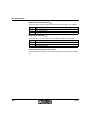
Parameter Lists
The following tables list the parameters of the Inline servo amplifier in their logical
groups (see "Object Dictionary (OD)" on page 3-14).
– The general device parameters contain information about the Inline servo
amplifier, such as manufacturer information and version number, nominal
values of the drive, and the operating mode.
– The additional parameters in "Speed specification" mode contain all other
information, which is required in addition to the general device parameters for
the speed controller function.
– The additional parameters in "Torque specification" mode contain all other
information, which is required in addition to the general device parameters for
the torque and current controller function.
– Parameter group 1 ("ParameterGroup1", index E000hex) groups together
twelve indices from the general device parameters and the additional
parameters in "Speed specification" mode as subindices.
The "Access" column describes how the parameters can be accessed:
– Read (R)
– Write (W)
– Read and write (RW)
Representation of
parameters by their
indices
A-8
The parameters are also listed according to their indices in Section A 2.5 on
page A-34, and their priority is indicated.
694900
694900
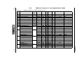
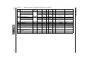
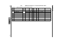
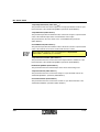
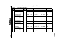
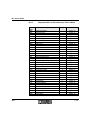
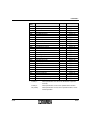
A 2.1
Table A-1
General Device Parameters
General device parameters
0002 ManufacturerID
0003 ManufacturerText
Var
Array
VisibleString
VisibleString
R
R
01
01
0004
0006
0007
0008
0009
000A
000B
Var
Var
Var
Var
Var
Var
Array[2]
VisibleString
VisibleString
VisibleString
VisibleString
VisibleString
VisibleString
R
R
R
R
R
R
VisibleString
VisibleString
VisibleString
UINT16
UINT16
INT32
INT32
USIGN32
USIGN32
INT32
USIGN16
USIGN16
INT16
R
R
R
R
R
RW
RW
RW
RW
R
RW
RW
RW
01
01
01
01
01
01
00
01
02
01
01
01
01
01
01
01
01
01
01
01
000C
000D
000E
0100
0101
0102
0103
0105
010C
010D
0121
DeviceRange
ProductRange
ProductName
ProductID
ProductText
OrderNumber
Version
Hardware
Firmware
ManufactureDate
CommunicationProfile
DeviceProfile
NominalVoltageMotor
NominalVoltageSupply
MotorCurrentWarning
SupplyVoltageWarning
MotorVoltageActualValue
NominalSpeedMotor
WarningCode
OutputLevelMode
Var
Var
Var
Var
Var
Var
Var
Var
Var
Var
Var
2 bytes
2 bytes
4 bytes
4 bytes
4 bytes
4 bytes
4 bytes
2 bytes
2 bytes
2 bytes
Value range
–
–
–
–
–
–
–
–
–
–
–
–
–
–
–
–
–
mV
mV
mA
mV
mV
rpm
–
–
–
–
–
–
–
–
–
–
–
YYYY-MM-DD
Default value
Phoenix Contact
GmbH & Co. KG
00A045
Connection
technology,
interface
technology,
automation
DRIVECOM drive
Inline
IB IL DC AR 48/10A
2819286
DC drive controller
2819286
1.20
2.00
2002-08-09
6
0022hex
12000 ... 48000 48000
12000 ... 48000 12000
0 ... 10000
10000
9000 ... 48000
9000
-60000 ... +60000 –
100 ... 30000
3000
0 ... 2
0
0: 4T mode
0
1: 2T mode
A-9
Parameters
Object Data type
Access Sub Length Unit
type
–
Var
VisibleString
R
01
1 byte per character
Index Parameter
(hex)
0001 ManufacturerName
General device parameters (Continued)
Index Parameter
(hex)
6000 INProcessDataDescription
ProcessDataLength
Index 1st parameter
Object Data type
type
Record –
Access Sub Length Unit
00 13 bytes
USIGN8
USIGN16
RW
RW
01
02
Sub-Index 1st parameter
Index 2nd parameter
USIGN8
USIGN16
RW
RW
03
04
Sub-Index 2nd parameter
Index 3rd parameter
USIGN8
USIGN16
RW
RW
05
06
Sub-Index 3rd parameter
Index 4th parameter
USIGN8
USIGN16
RW
RW
07
08
RW
RW
09
00
Byte
–
4
–
0000hex ... 6079hex 6041hex (status
word)
1 byte
–
00 ... 09
00
2 bytes
–
0000hex ... 6079hex 0000hex (status
word uses 2 bytes)
1 byte
–
00 ... 09
00
2 bytes
–
0000hex ... 6079hex 6044hex (speed
actual value)
1 byte
–
00 ... 09
00
2 bytes
–
0000hex ... 6079hex 0000hex (speed
actual value uses
2 bytes)
1 byte
–
00 ... 09
00
13 bytes –
–
–
USIGN8
USIGN16
RW
RW
01
02
1 byte
2 bytes
Sub-Index 1st parameter
Index 2nd parameter
USIGN8
USIGN16
RW
RW
03
04
1 byte
2 bytes
Sub-Index 2nd parameter
Index 3rd parameter
USIGN8
USIGN16
RW
RW
05
06
1 byte
2 bytes
Sub-Index 3rd parameter
Index 4th parameter
USIGN8
USIGN16
RW
RW
07
08
1 byte
2 bytes
Sub-Index 4th parameter
USIGN8
RW
09
1 byte
USIGN8
Record –
–
Default value
RW
Sub-Index 4th parameter
6001 OUTProcessDataDescription
ProcessDataLength
Index 1st parameter
–
Value range
–
1 byte
2 bytes
694900
Byte
–
4
–
0000hex ... 6079hex 6040hex (control
word)
–
00 ... 09
00
–
0000hex ... 6079hex 0000hex (control
word uses 2 bytes)
–
00 ... 09
00
–
0000hex ... 6079hex 6042hex (speed
setpoint)
–
00 ... 09
00
–
0000hex ... 6079hex 0000hex (speed
setpoint uses
2 bytes)
–
00 ... 09
00
IB IL DC AR 48/10A
A-10
Table A-1
694900
Table A-1
Index
(hex)
6002
6015
603F
6040
6041
6060
General device parameters (Continued)
Parameter
Object
type
1 byte
Array[1]
2 bytes
2 bytes
2 bytes
Var
OctetString
INT16
OctetString
OctetString
OctetString
INT16
6061 ModeDisplay
Var
6079 IntermediateCircuitVoltage
Var
OUTProcessDataEnable
DeviceTemperature
ErrorCode
ControlWord
StatusWord
ModeSelectionCode
Data type
Access Sub Length Unit
RW
R
R
RW
R
RW
01
01
01
01
01
01
1 byte
2 bytes
2 bytes
2 bytes
2 bytes
2 bytes
–
°C
–
–
–
–
INT16
R
01
2 bytes
–
USIGN16
R
01
2 bytes
V
Value range
00hex ... FFhex
–
0000hex ... 8100hex
0000hex ... FFFFhex
0000hex ... FFFFhex
0: Off
2: Speed
specification
4: Torque
specification
0: Off
2: Speed
specification
4: Torque
specification
0 ... 65
Default value
FFhex
–
–
–
–
2
2
–
Parameters
A-11
IB IL DC AR 48/10A
Manufacturer-Specific Parameters (Index 0001hex to 000Ahex)
These parameters contain information about the manufacturer and product in the
form of strings.
Version (Index 000Bhex)
The "Version" parameter contains the hardware and firmware version.
– Hardware: e.g., "1.20"
– Firmware: e.g., "2.00"
ManufactureDate (Index 000Chex)
This parameter contains the release date of the current firmware.
CommunicationProfile (Index 000Dhex)
This parameter contains conditions for communication with the module and
definitions for communication services and parameters.
DeviceProfile (Index 000Ehex)
The device profile specifies the device functions that are visible via the
communication (DRIVECOM profile 22).
NominalVoltageMotor (Index 0100hex)
This parameter defines the output voltage of the Inline servo amplifier for the
nominal speed of the motor. This motor characteristic value can be found in the data
sheet for the motor (see "NominalSpeedMotor (Index 010Chex)" on page A-13).
NominalVoltageSupply (Index 0101hex)
The limit value for the error (USmin) is derived from the "NominalVoltageSupply"
parameter (USn).
USmin = 0.75 * USn
If the power supply falls below this voltage limit value, an error is indicated.
MotorCurrentWarning (Index 0102hex)
If the measured motor current exceeds this limit value, a warning is generated (see
"WarningCode (Index 010Dhex)" on page A-13).
SupplyVoltageWarning (Index 0103hex)
If the measured supply voltage falls below this limit value, a warning is generated
(see "WarningCode (Index 010Dhex)" on page A-13).
A-12
694900
Parameters
MotorVoltageActualValue (Index 0105hex)
This parameter contains the current value of the measured motor voltage in
millivolts (mV).
NominalSpeedMotor (Index 010Chex)
This parameter defines the speed at which the motor runs when the nominal motor
voltage is applied. This motor characteristic value can be found in the data sheet
for the motor (see "NominalVoltageMotor (Index 0100hex)" on page A-12).
WarningCode (Index 010Dhex)
Any warnings that are generated are stored in this parameter until they are deleted
by writing 0 to the warning code. Unlike errors, warnings have no effect on the
operation of the Inline servo amplifier.
Read:
Value
0
1
2
Meaning
No warning
Motor current has exceeded the value of the "MotorCurrentWarning"
parameter (index 0102hex)
Power supply voltage has fallen below the value of the
"SupplyVoltageWarning" parameter (index 0103hex)
Write:
Value
0
Meaning
Deletes the warning code
OutputLevelMode (Index 0121hex)
Value
0
1
Meaning
4T mode of the output level:
High level of efficiency (for motors with a high current requirement)
2T mode of the output level:
Lower temperature rise on the motor at a speed of 0 rpm (for small
motors with low inductance and a low current requirement)
See also "Operating Modes of the Output Level" on page 1-8.
694900
A-13
IB IL DC AR 48/10A
INProcessDataDescription (Index 6000hex)
This parameter defines the parameters that should be accessed via IN process
data:
Subindex Assignment
01
IN process data length (always 4 bytes for the Inline servo amplifier).
02
Index of the parameter, which should be mapped to the IN process
data word starting from byte 0.
03
Subindex of the parameter, which should be mapped to the IN process
data word starting from byte 0.
04
Index of the parameter, which should be mapped to the IN process
data word starting from byte 1. If a 16-bit parameter should be mapped
to IN process data word 0, its high byte appears in byte 0 of the IN
process data word and its low byte appears in byte 1.
05
06
07
08
09
A-14
In this case, subindex 4 of the IN process data description has the
value 0000hex.
Subindex of the parameter, which should be mapped to the IN process
data word starting from byte 1.
Index of the parameter, which should be mapped to the IN process
data word starting from byte 2.
Subindex of the parameter, which should be mapped to the IN process
data word starting from byte 2.
Index of the parameter, which should be mapped to the IN process
data word starting from byte 3. If a 16-bit parameter should be mapped
to IN process data word 1, its high byte appears in byte 2 of the IN
process data word and its low byte appears in byte 3.
In this case, subindex 8 of the IN process data description has the
value 0000hex.
Subindex of the parameter, which should be mapped to the IN process
data word starting from byte 3.
694900
Parameters
OUTProcessDataDescription (Index 6001hex)
This parameter defines the parameters that should be accessed via OUT process
data:
Subindex Assignment
01
OUT process data length (always 4 bytes for the Inline servo
amplifier).
02
Index of the parameter, which should be mapped to the OUT process
data word starting from byte 0.
03
Subindex of the parameter, which should be mapped to the OUT
process data word starting from byte 0.
04
Index of the parameter, which should be mapped to the OUT process
data word starting from byte 1. If a 16-bit parameter should be mapped
to OUT process data word 0, its high byte appears in byte 0 of the OUT
process data word and its low byte appears in byte 1.
05
06
07
08
09
694900
In this case, subindex 4 of the OUT process data description has the
value 0000hex.
Subindex of the parameter, which should be mapped to the OUT
process data word starting from byte 1.
Index of the parameter, which should be mapped to the OUT process
data word starting from byte 2.
Subindex of the parameter, which should be mapped to the OUT
process data word starting from byte 2.
Index of the parameter, which should be mapped to the OUT process
data word starting from byte 3. If a 16-bit parameter should be mapped
to OUT process data word 1, its high byte appears in byte 2 of the OUT
process data word and its low byte appears in byte 3.
In this case, subindex 8 of the OUT process data description has the
value 0000hex.
Subindex of the parameter, which should be mapped to the OUT
process data word starting from byte 3.
A-15
IB IL DC AR 48/10A
OUTProcessDataEnable (Index 6002hex)
In order to ensure data consistency when switching to the parameters specified in
the OUT process data description, these parameters are temporarily separated
from the process data before switching over. The value 00hex is written to the
"OUTProcessDataEnable" parameter.
Once the "OUTProcessDataDescription" parameter (index 6001hex) has been
written, the OUT process data is reenabled by writing the value FFhex to the
"OUTProcessDataEnable" parameter (index 6002hex). As long as the parameters
specified in the OUT process data description are separated from the process data,
their values do not change, even if the OUT process data changes.
DeviceTemperature (Index 6015hex)
This parameter displays the current temperature of the output level in °C.
– At temperatures above 85°C (185°F) the Inline servo amplifier switches to the
"Error: Output level overtemperature" state.
– At temperatures above 75°C (167°F) the internal fan is activated.
– At temperatures below 65°C (149°F) the internal fan is deactivated.
A-16
694900
Parameters
ErrorCode (Index 603Fhex)
If an error is detected, the device control enters the "Error response active" state
(see Figure 3-3 on page 3-8). Any errors that occur are stored in this parameter
until they are deleted with the "Reset error" command.
Error Code Cause of the Error
(hex)
0000
No error
1000
General device error
2340
3211
4210
Short circuit at the motor output
Surge voltage of the power section
supply
Undervoltage of the power section
supply
Output level overtemperature
6010
Software reset (watchdog)
6100
Firmware checksum
7500
SUPI chip initialization
8100
Communication
3221
694900
Remedy
–
Disconnect the Inline servo amplifier.
If necessary, replace the Inline servo amplifier.
Check the motor cable for short circuits.
Check the supply voltage of the power section,
especially in the event of feedback when braking.
Check the supply voltage of the power section,
especially in the event of higher current loads.
Let the Inline servo amplifier cool down. Observe the
current load of the Inline servo amplifier in relation to the
current derating curve.
Disconnect the Inline servo amplifier.
If necessary, replace the Inline servo amplifier.
Disconnect the Inline servo amplifier.
If necessary, replace the Inline servo amplifier.
Disconnect the Inline servo amplifier.
If necessary, replace the Inline servo amplifier.
Bus communication was interrupted.
Execute the "Reset error" command.
A-17
IB IL DC AR 48/10A
ControlWord (Index 6040hex)
This parameter represents the 16-bit DRIVECOM control word. This parameter is
written by default via OUT process data word 0. In this case, the control word
cannot be written via the PCP channel.
Bit assignment:
Bit
0
1
2
3
4
5
6
7
8
9
10
11
12
13
14
15
*
A-18
Assignment
Switch on
Disable voltage
Quick stop
Enable operation
–
–
–
Reset error
–
–
–
Activate LowRuntime2*
–
–
–
–
As long as bit 11 is set, the "LowRuntime2" parameter (index 0120hex) is used
instead of the "LowRuntime" parameter (index 6050hex).
This means that you can switch very quickly between two different braking
ramps.
694900
Parameters
StatusWord (Index 6041hex)
This parameter represents the 16-bit DRIVECOM status word. This parameter is
read by default via OUT process data word 0.
Bit assignment:
Bit
0
1
2
3
4
5
6
7
8
9
10
11
12
13
14
15
694900
Assignment
Ready to operate
ON
Operation enabled
Error
Voltage disabled
Quick stop
Start inhibit
Warning
Message
(Value: 0)
Remote
(Value: 1)
Setpoint reached
Limit value
–
–
–
–
A-19
IB IL DC AR 48/10A
ModeSelectionCode (Index 6060hex)
This parameter is used to select the operating mode of the Inline servo amplifier.
Value
0
2
4
Meaning
Off
Speed specification
Torque specification
ModeDisplay (Index 6061hex)
This parameter is used to read the current mode of the Inline servo amplifier.
Value
0
2
4
Meaning
Off
Speed specification
Torque specification
IntermediateCircuitVoltage (Index 6079hex)
This parameter describes the current voltage measured value of the power supply
US.
A-20
694900
694900
A 2.2
Table A-2
Index
(hex)
0107
0108
0109
010A
010B
0120
6042
6043
6044
6046
6047
6048
6049
604A
Additional Parameters in "Speed Specification" Mode
Additional parameters in "Speed specification" mode
Parameter
Data type Access Sub Length Unit
USIGN16
USIGN16
USIGN16
USIGN16
USIGN16
USIGN32
INT16
INT16
INT16
–
USIGN32
USIGN32
RW
RW
RW
RW
RW
RW
RW
R
R
RW
RW
RW
USIGN32
USIGN32
USIGN32
USIGN32
–
USIGN32
USIGN16
–
USIGN32
USIGN16
–
USIGN32
USIGN16
RW
RW
RW
RW
RW
RW
RW
RW
RW
RW
RW
RW
RW
Array[4]
Record
Record
Record
01 2 bytes
01 2 bytes
01 2 bytes
01 2 bytes
01 2 bytes
01 4 bytes
01 2 bytes
01 2 bytes
01 2 bytes
00 8 bytes
01 4 bytes
02 4 bytes
00 16 bytes
01 4 bytes
02 4 bytes
03 4 bytes
04 4 bytes
00 6 bytes
01 4 bytes
02 2 bytes
00 6 bytes
01 4 bytes
02 2 bytes
00 6 bytes
01 4 bytes
02 2 bytes
–
–
–
–
–
ms
rpm
rpm
rpm
–
rpm
rpm
–
rpm
rpm
rpm
rpm
–
rpm
s
–
rpm
s
–
rpm
s
Value range
0 ... 65535
0 ... 65535
0 ... 65535
0 ... 65535
0 ... 65535
0 ... 4294967294
-30000 ... +30000
–
–
–
0 ... 30000
0 ... 30000
–
0 ... 30000
0 ... 30000
0 ... 30000
0 ... 30000
–
1 ... 1000000
0 ... 1000
–
1 ... 1000000
0 ... 1000
–
1 ... 1000000
0 ... 1000
Default value
200
30
800
100
0
1
0
–
–
–
0
30000
–
0
30000
0
30000
–
2000
1
–
2000
1
–
5000
1
A-21
Parameters
KPCurrentController
KICurrentController
KPSpeedController
KISpeedController
IxRCompensation
LowRuntime2
SpeedSetpoint
SpeedReferenceVariable
SpeedActualValue
SpeedMinMaxValue
SpeedMinValue
SpeedMaxValue
SpeedMinMax
SpeedMinPos
SpeedMaxPos
SpeedMinNeg
SpeedMaxNeg
SpeedAcceleration
DeltaSpeed
DeltaTime
SpeedDelay
DeltaSpeed
DeltaTime
SpeedQuickStop
DeltaSpeed
DeltaTime
Object
type
Var
Var
Var
Var
Var
Var
Var
Var
Var
Array[2]
Additional parameters in "Speed specification" mode (Continued)
Index Parameter
(hex)
604B SetpointFactor
Numerator
Denominator
Object Data type Access Sub Length Unit
type
Array[2] –
RW
00 4 bytes
–
INT16
RW
01 2 bytes
–
INT16
RW
02 2 bytes
–
604C DimensionFactor
Numerator
Denominator
Array[2] –
INT32
INT32
RW
RW
RW
00
01
02
8 bytes
4 bytes
4 bytes
604E
604F
6050
6051
6052
Var
Var
Var
Var
Var
USIGN32
USIGN32
USIGN32
USIGN32
INT16
RW
RW
RW
RW
RW
01
01
01
01
01
4 bytes
4 bytes
4 bytes
4 bytes
2 bytes
Var
INT16
R
01
2 bytes
Var
INT16
R
01
2 bytes
SpeedReferenceValue
HighRuntime
LowRuntime
QuickStopTime
PercentageSetpoint
6053 PercentageReferenceVariable
6054 PercentageActualValue
Value range
–
-10000 ... +10000
-10000 ... +10000
(without 0)
–
–
– -100000 ... +100000
– -100000 ... +100000
(without 0)
rpm
0 ... 30000
ms
1 ... 1000000
ms
1 ... 1000000
ms
1 ... 1000000
–
-32766 ... +32766
(16383 = 100%)
–
–
–
16383 = 100%
Default value
–
1
1
–
1
1
1000
500
500
200
0%
–
–
IB IL DC AR 48/10A
A-22
Table A-2
694900
Parameters
KPCurrentController (Index 0107hex)
This parameter contains the proportional factor of the PI filter of the current
controller (see "Adjusting Control Parameters" on page 1-12).
KICurrentController (Index 0108hex)
This parameter contains the integral factor of the PI filter of the current controller
(see "Adjusting Control Parameters" on page 1-12).
KPSpeedController (Index 0109hex)
This parameter contains the proportional factor of the PI filter of the speed controller
(see "Adjusting Control Parameters" on page 1-12).
KISpeedController (Index 010Ahex)
This parameter contains the integral factor of the PI filter of the speed controller
(see "Adjusting Control Parameters" on page 1-12).
IxRCompensation (Index 010Bhex)
This parameter contains the IxR compensation factor of the speed controller (see
"Adjusting Control Parameters" on page 1-12).
LowRuntime2 (Index 0120hex)
Together with the "SpeedReferenceValue" parameter (index 604Ehex), this
parameter is used to define the steepness of braking ramp 2. "LowRuntime2"
(braking ramp 2, index 0120hex) replaces "LowRuntime" (braking ramp,
index 6050hex), as long as the "Activate LowRuntime2" bit is set (bit 11 of the
control word). This means that you can switch very quickly between two different
braking ramps.
For the "LowRuntime2" parameter:
Braking ramp 2 = Speed reference value/LowRuntime2
SpeedSetpoint (Index 6042hex)
The "SpeedSetpoint" parameter is the default value for the speed at the motor axis
or at the load. It is multiplied by the dimension factor ("DimensionFactor" parameter,
index 604Chex) and the setpoint factor ("SetpointFactor" parameter,
index 604Bhex).
If the servo amplifier is to be supplied with other units (e.g., m/s or m/min), the
dimension factor is used for adjustments.
Multiplying the speed setpoint by the dimension factor converts the speed setpoint
into rpm, if the dimension factor equals 1.
694900
A-23
IB IL DC AR 48/10A
SpeedReferenceVariable (Index 6043hex)
The speed reference variable is the speed from the ramp function standardized to
the speed setpoint unit.
SpeedActualValue (Index 6044hex)
The speed actual value is the speed at the motor axis or load standardized to the
speed setpoint unit. It is calculated from the measured motor voltage
("MotorVoltageActualValue" parameter, index 0105hex) using the
"NominalVoltageMotor" parameter (index 0100hex) and the "NominalSpeedMotor"
parameter (index 010Chex).
SpeedMinMaxValue (Index 6046hex)
This parameter is used to limit the speed between the minimum and maximum
speed (see "SpeedMinMax (Index 6047hex)" on page A-25).
As it is given as a value, the speed limits apply to both the positive and negative
direction.
Subparameters
The "SpeedMinMaxValue" parameter consists of the "SpeedMinValue" and
"SpeedMaxValue" subparameters.
When writing, the "SpeedMaxValue" subparameter is internally mapped to the
"SpeedMaxPos" and "SpeedMaxNeg" values.
When writing, the "SpeedMinValue" subparameter is internally mapped to the
"SpeedMinPos" and "SpeedMinNeg" values.
The unit of speed depends on the dimension factor and corresponds to the speed
setpoint unit (index 6042hex).
A-24
694900
Parameters
SpeedMinMax (Index 6047hex)
This parameter is used to limit the motor speed between the minimum and
maximum speed (positive and negative working area).
Subparameters
The "SpeedMinMax" parameter consists of the "SpeedMinPos", "SpeedMaxPos",
"SpeedMinNeg", and "SpeedMaxNeg" subparameters (see Figure A-9).
When writing this parameter, the "SpeedMinPos" subparameter is mapped to the
"SpeedMinValue" subparameter (index 6046hex), and the "SpeedMaxPos"
subparameter is mapped to the "SpeedMaxValue" subparameter (index 6046hex).
V
V
m a x
V
-V
m a x
-V
o u t
m in
m in
V
m in
-V
m in
-V
m a x
V
m a x
V
s e tp o in t
6 9 4 9 A 0 3 5
Figure A-9
694900
Speed limitation using "SpeedMinMax" (index 6047hex)
A-25
IB IL DC AR 48/10A
SpeedAcceleration (Index 6048hex)
Subparameters
The Inline servo amplifier calculates the acceleration ramp using the "DeltaSpeed"
and "DeltaTime" subparameters:
Acceleration ramp = Delta speed/delta time
The "DeltaSpeed" unit depends on the dimension factor and corresponds to the
speed setpoint unit (index 6042hex).
When writing this parameter, the "HighRuntime" parameter (index 604Fhex) is
overwritten using the "SpeedReferenceValue" parameter (index 604Ehex).
SpeedDelay (Index 6049hex)
Subparameters
The Inline servo amplifier calculates the braking ramp using the "DeltaSpeed" and
"DeltaTime" subparameters:
Braking ramp = Delta speed/delta time
The "DeltaSpeed" unit depends on the dimension factor and corresponds to the
speed setpoint unit (index 6042hex).
When writing this parameter, the "LowRuntime" parameter (index 6050hex) is
overwritten using the "SpeedReferenceValue" parameter (index 604Ehex).
SpeedQuickStop (Index 604Ahex)
Subparameters
The Inline servo amplifier calculates the quick stop ramp using the "DeltaSpeed"
and "DeltaTime" subparameters:
Quick stop ramp = Delta speed/delta time
The "DeltaSpeed" unit depends on the dimension factor and corresponds to the
speed setpoint unit (index 6042hex).
When writing this parameter, the "QuickStopTime" parameter (index 6051hex) is
overwritten using the "SpeedReferenceValue" parameter (index 604Ehex).
A-26
694900
Parameters
SetpointFactor (Index 604Bhex)
Subparameters
The "SetpointFactor" parameter consists of a "Numerator" subparameter and a
"Denominator" subparameter, and is calculated as follows:
Setpoint factor = Numerator/denominator
The setpoint factor is used to change the resolution and the setting range of the
setpoint specification. It is only included in the setpoint specification and the output
variables of the speed function.
DimensionFactor (Index 604Chex)
The dimension factor enables the use of units other than rpm (revolutions per
minute) outside the Inline servo amplifier.
The Inline servo amplifier uses the dimension factor to convert:
– All incoming values to rpm
– All outgoing values back to the original unit
The dimension factor is used to:
– Determine a gear factor
– Standardize values for frequencies or user-specific units
It affects the following variables:
– Setpoint specification
– Speed limitation
– Ramp function
– Output variables for the speed function
Subparameters
The "DimensionFactor" parameter consists of a "Numerator" subparameter and a
"Denominator" subparameter, and is calculated as follows:
Dimension factor = Numerator/denominator
The dimension factor describes the relationship between the "NominalSpeedMotor"
parameter (index 010Chex) and the "SpeedReferenceValue" parameter
(index 604Ehex).
Example
The dimension factor for a drive with a speed reference value of v = 800 mm/s and
a motor with a nominal speed of n = 3000 rpm is as follows:
D = 3000 rpm/800 mm/s (numerator = 3000, denominator = 800, setpoint factor = 1)
694900
A-27
IB IL DC AR 48/10A
SpeedReferenceValue (Index 604Ehex)
This parameter is the speed reference value and is used to calculate percentage
values and ramps.
The unit of speed depends on the dimension factor and corresponds to the speed
setpoint unit (index 6042hex).
HighRuntime (Index 604Fhex)
This parameter writes the acceleration ramp using the high runtime from zero to the
speed reference value (index 604Ehex).
Acceleration ramp = Speed reference value/high runtime
When writing this parameter, the "SpeedAcceleration" parameter (index 6048hex)
is written with an appropriately converted value. The "DeltaTime" subparameter
is set to 1 s.
LowRuntime (Index 6050hex)
This parameter writes the braking ramp using the low runtime from the speed
reference value (index 604Ehex) to zero.
Braking ramp = Speed reference value/low runtime
When writing this parameter, the "SpeedDelay" parameter (index 6049hex) is
written with an appropriately converted value. The "DeltaTime" subparameter is
set to 1 s.
QuickStopTime (Index 6051hex)
This parameter writes the quick stop ramp using the quick stop time from the speed
reference value (index 604Ehex) to zero.
Quick stop ramp = Speed reference value/quick stop time
When writing this parameter, the "SpeedQuickStop" parameter (index 604Ahex)
is written with an appropriately converted value. The "DeltaTime" subparameter
is set to 1 s.
A-28
694900
Parameters
PercentageSetpoint (Index 6052hex)
This parameter writes the speed setpoint as a percentage of the speed reference
value (index 604Ehex).
A value of 16383 is equal to 100%, i.e., the value range is between -200%
and +200% of the speed reference value.
PercentageReferenceVariable (Index 6053hex)
This parameter writes the current value of the reference variable for the internal
speed controller as a percentage of the speed reference value (index 604Ehex).
A value of 16383 is equal to 100%, i.e., the value range is between -200%
and +200% of the speed reference value.
PercentageActualValue (Index 6054hex)
This parameter writes the current speed actual value as a percentage of the speed
reference value (index 604Ehex).
A value of 16383 is equal to 100%, i.e., the value range is between -200%
and +200% of the speed reference value.
694900
A-29
Table A-3
Additional Parameters in "Torque Specification" Mode
Additional parameters in "Torque specification" mode
Index Parameter
(hex)
0104 NominalCurrentMotor
0106 CurrentMinMaxValue
CurrentMinValue
CurrentMaxValue
6071 TorqueSetpointExternal
6072 TorqueMaxValue
6073 CurrentMaxValue
6074 TorqueReferenceVariable
6076 NominalTorqueMotor
Object Data type
type
Var
USIGN32
Array[2] –
USIGN16
USIGN16
Var
INT16
Var
USIGN16
Var
USIGN16
Var
INT16
Var
USIGN16
6077 TorqueActualValue
6078 CurrentActualValue
Var
Var
INT16
INT16
Access Sub Length Unit
RW
RW
RW
RW
RW
RW
RW
R
RW
01
00
01
02
01
01
01
01
01
4 bytes
4 bytes
2 bytes
2 bytes
2 bytes
2 bytes
2 bytes
2 bytes
2 bytes
R
R
01
01
2 bytes
2 bytes
mA
–
‰
‰
‰
‰
‰
‰
0.1
Nm
‰
‰
Value range
Default value
0 ... 10000
–
0 ... 65535
0 ... 65535
-32768 ... +32767
0 ... 65535
0 ... 65535
-32768 ... +32767
1 ... 1000
10000
–
0
1000
0
1000
1000
–
100 * 0.1 = 10
–
–
–
–
IB IL DC AR 48/10A
A-30
A 2.3
694900
Parameters
NominalCurrentMotor (Index 0104hex)
This parameter is the reference value for calculating the current actual value
("CurrentActualValue" parameter, index 6078hex) and the torque actual value
("TorqueActualValue" parameter, index 6077hex) on the basis that the torque is
proportional to the motor current.
CurrentMinMaxValue (Index 0106hex)
Subparameters
The "CurrentMinValue" and "CurrentMaxValue" subparameters are used to limit the
motor current between these values, as long as the setpoint is not equal to zero
(see Figure A-10).
The universal limit of 10 A can never be exceeded.
When writing the "CurrentMaxValue" subparameter, the "CurrentMaxValue"
parameter (index 6073hex) is overwritten.
Io
-Im
a x
-Im
Im
a x
Im
in
u t
in
Im
-Im
in
-Im
a x
in
Im
a x
Is
e tp o in t
6 9 4 9 A 0 3 6
Figure A-10
694900
Method of operation of the current limiter
(Input variable Isetpoint, reference variable Iout)
A-31
IB IL DC AR 48/10A
TorqueSetpointExternal (Index 6071hex)
This parameter writes the relative setpoint for "Torque specification" mode as a per
thousand value of the "NominalTorqueMotor" parameter (index 6076hex).
TorqueMaxValue (Index 6072hex)
This parameter specifies the maximum value of the motor torque as a per thousand
value of the nominal torque and is used to limit the motor torque.
This parameter has the same effect as the "CurrentMaxValue" parameter
(index 6073hex).
CurrentMaxValue (Index 6073hex)
This parameter specifies the maximum value of the motor current as a per thousand
value of the nominal current and is used to limit the motor current.
When writing this parameter, the "CurrentMaxValue" subparameter
(index 0106hex, subindex 02) is overwritten.
TorqueReferenceVariable (Index 6074hex)
This parameter writes the current value of the torque reference variable as a per
thousand value of the "NominalTorqueMotor" parameter (index 6076hex).
NominalTorqueMotor (Index 6076hex)
This parameter writes the nominal torque of the motor that is being used.
TorqueActualValue (Index 6077hex)
This parameter writes the current motor torque as a per thousand value of the
"NominalTorqueMotor" parameter (index 6076hex).
CurrentActualValue (Index 6078hex)
This parameter writes the current motor current as a per thousand value of the
"NominalCurrentMotor" parameter (index 0104hex).
A-32
694900
694900
A 2.4
Table A-4
ParameterGroup1 (Index E000hex)
ParameterGroup1 (index E000hex)
Index Parameter
(hex)
E000 ParameterGroup1
NominalVoltageMotor
(see index 0100hex)
NominalVoltageSupply
(see index 0101hex)
KPCurrentController
(see index 0107hex)
KICurrentController
(see index 0108hex)
KPSpeedController
(see index 0109hex)
KISpeedController
(see index 010Ahex)
IxRCompensation
(see index 010Bhex)
LowRuntime2
(see index 0120hex)
SpeedReferenceValue
(see index 604Ehex)
HighRuntime
(see index 604Fhex)
LowRuntime
(see index 6050hex)
QuickStopTime
(see index 6051hex)
Object Data type Access Sub Length Unit
type
Record –
RW
00 38 bytes –
INT32
RW
01 4 bytes mV
Value range
Default value
–
12000 ... 48000
–
48000
12000
INT32
RW
02
4 bytes
mV
12000 ... 48000
USIGN16
RW
03
2 bytes
–
0 ... 65535
200
USIGN16
RW
04
2 bytes
–
0 ... 65535
30
USIGN16
RW
05
2 bytes
–
0 ... 65535
800
USIGN16
RW
06
2 bytes
–
0 ... 65535
100
USIGN16
RW
07
2 bytes
–
0 ... 65535
0
USIGN32
RW
08
4 bytes
ms
0 ... 4294967294
1
USIGN32
RW
09
4 bytes
rpm
0 ... 30000
1000
USIGN32
RW
10
4 bytes
ms
0 ... 1000000
500
USIGN32
RW
11
4 bytes
ms
0 ... 1000000
500
USIGN32
RW
12
4 bytes
ms
0 ... 1000000
200
Parameters
A-33
IB IL DC AR 48/10A
A 2.5
Index
(hex)
0001
0002
0003
0004
0006
0007
0008
0009
000A
000B
000C
000D
000E
0100
0101
0102
0103
0104
0105
0106
0107
0108
0109
010A
010B
010C
010D
0120
0121
6000
6001
6002
6015
603F
6040
A-34
Representation of Parameters by Their Indices
Parameter
ManufacturerName
ManufacturerID
ManufacturerText
DeviceRange
ProductRange
ProductName
ProductID
ProductText
OrderNumber
Version
ManufactureDate
CommunicationProfile
DeviceProfile
NominalVoltageMotor
NominalVoltageSupply
MotorCurrentWarning
SupplyVoltageWarning
NominalCurrentMotor
MotorVoltageActualValue
CurrentMinMaxValue
KPCurrentController
KICurrentController
KPSpeedController
KISpeedController
IxRCompensation
NominalSpeedMotor
WarningCode
LowRuntime2
OutputLevelMode
INProcessDataDescription
OUTProcessDataDescription
OUTProcessDataEnable
DeviceTemperature
ErrorCode
ControlWord
Priority*
1
1
1
2
2
2
2
2
1
2
2
See
page A-12
page A-12
page A-12
page A-12
page A-12
page A-12
page A-12
page A-12
page A-12
page A-12
page A-12
page A-12
page A-12
page A-12
page A-12
page A-12
page A-12
page A-31
page A-13
page A-31
page A-23
page A-23
page A-23
page A-23
page A-23
page A-13
page A-13
page A-23
page A-13
page A-14
page A-16
page A-16
page A-16
page A-17
page A-18
694900
Parameters
Index
(hex)
6041
6042
6043
6044
6046
6047
6048
6049
604A
604B
604C
604E
604F
6050
6051
6052
6053
6054
6060
6061
6071
6072
6073
6074
6076
6077
6078
6079
E000
*
694900
Parameter
Priority*
StatusWord
SpeedSetpoint
SpeedReferenceVariable
SpeedActualValue
SpeedMinMaxValue
SpeedMinMax
SpeedAcceleration
SpeedDelay
SpeedQuickStop
SetpointFactor
DimensionFactor
SpeedReferenceValue
HighRuntime
LowRuntime
QuickStopTime
PercentageSetpoint
PercentageReferenceVariable
PercentageActualValue
ModeSelectionCode
ModeDisplay
TorqueSetpointExternal
TorqueMaxValue
CurrentMaxValue
TorqueReferenceVariable
NominalTorqueMotor
TorqueActualValue
CurrentActualValue
IntermediateCircuitVoltage
ParameterGroup1
2
2
2
1
2
2
2
1
See
page A-19
page A-23
page A-24
page A-24
page A-24
page A-25
page A-26
page A-26
page A-26
page A-27
page A-27
page A-28
page A-28
page A-28
page A-28
page A-29
page A-29
page A-29
page A-20
page A-20
page A-32
page A-32
page A-32
page A-32
page A-32
page A-32
page A-32
page A-20
page A-33
Priority 1:
These parameters must be set for the device to operate
correctly.
Priority 2:
These parameters can be set to optimize drive function.
No priority:
These parameters are only set for special functions, not for
normal operation.
A-35
IB IL DC AR 48/10A
A-36
694900
Appendix B
B
B1
Technical Appendix
Technical Data
General Data
Order Designation
Order No.
Housing dimensions (width x height x depth)
Housing material
Heatsink material
Weight (typical)
Permissible temperature (operation)
Permissible temperature (storage/transport)
Permissible humidity (operation)
Permissible humidity (storage/transport with unused
interfaces [standard packaging])
IB IL DC AR 48/10A
28 19 28 6
48 mm x 85 mm x 166 mm (1.890 x 3.346 x 6.535 in.)
PA 6.6; black, anodized aluminum
Aluminum
460 g
-25°C to +55°C (-13°F to +131°F)
-25°C to +85°C (-13°F to +185°F)
75% permanent, 85% occasionally
75% permanent, 85% occasionally
For a short period, slight condensation may appear on the outside of the housing if, for example,
the module is brought into a closed room from a vehicle.
Permissible air pressure (operation)
Permissible air pressure (storage/transport)
Degree of protection
Class of protection
Mechanical Requirements
Vibration test
sinusoidal vibrations according to IEC 60068-2-6;
EN 60068-2-6
Shock test
according to IEC 60068-2-27, EN 60068-2-27
Free fall according to IEC 60068-2-32
Power Supply
Status indicators
Connection method
Supply voltage US
Supply current
Surge voltage shutdown
694900
80 kPa to 106 kPa
(up to 2000 m [6562 ft.] above sea level)
70 kPa to 106 kPa
(up to 3000 m [9843 ft.] above sea level)
IP20 according to DIN 40050
Class 3 according to VDE 0106, IEC 60536
2g load, 2 hours in each space direction
25g for 1 ms, three shocks in each space direction
1 m (3.281 ft.)
US LED
2-pos. COMBICON connector
12 V DC to 48 V DC ±15%
0 A to 10 A
US > 60 V DC
B-1
IB IL DC AR 48/10A
Outputs
Number
Connection
Connection method
Output voltage
Motor cable
Continuous current
Starting current
Motor current limiting
Maximum motor voltage
Function
Braking
Minimum motor inductance
1
1 permanently excited DC motor with brushgears
3-pos. COMBICON connector with shield clamp
± supply voltage US, maximum
Mean value 92% of US, maximum
2-wire, shielded
10 A, maximum (see "Selecting Compatible Motors"
on page 2-10)
10 A, maximum
0 A to 10 A (can be set via bus)
±65 V DC
4 quadrant servo controller
Energy fed back to the power supply unit
(brake chopper may be required)
200 µH at US = 48 V DC
100 µH at US = 24 V DC
Cycle Time of the Internal Digital Controllers
Speed controller
Torque/current controller
1 ms
250 µs
Electrical Isolation
Logic UL / I/O / motor
500 V AC test voltage
Pulse Wide Modulation (PWM)
Clock frequency
20 kHz
Interfaces
Local bus
Communications power UL
Current consumption at UL
Module supply UM
Current consumption at UM
Inline potential jumper
7.5 V DC (via potential jumper)
45 mA, typical
24 V DC (via potential jumper)
65 mA, typical
Approvals
CE
UL
Yes
Applied for
B-2
694900
Appendix B
Conformance With EMC Directive 89/336/EEC
Conformance is only ensured if the shielded motor cable is connected to the FE terminal and the
module is connected to functional earth ground via the DIN rail.
Noise Immunity Test According to EN 50082-2:1995
Electrostatic discharge (ESD)
EN 61000-4-2:1995/
IEC 61000-4-2
Electromagnetic fields
Fast transients (burst)
Conducted interference
EN 61000-4-3:1993/
IEC 61000-4-3
EN 61000-4-4:1995/
IEC 61000-4-4
EN 61000-4-6:1993/
IEC 61000-4-6
Noise Emission Test According to EN 50081-2:1993
Noise emission of housing
EN 55011:1991
694900
Criterion B
6 kV contact discharge
8 kV air discharge
Criterion A
Field strength: 10 V/m
Criterion B
Supply lines: 2 kV
Signal/data lines: 2 kV
Criterion A
Interfaces: 1kV
Criterion A, test voltage 10 V
Class A
B-3
IB IL DC AR 48/10A
B2
Ordering Data
Description
Inline servo amplifier for DC motors, with
COMBICON connectors
Positioning CPU as the positioning control system
for multi-axis point-to-point control systems, with
connectors and labeling fields
Positioning CPU as the positioning control system
for multi-axis point-to-point control systems, without
connectors and labeling fields
Order Designation
IB IL DC AR 48/10A
Order No.
28 19 28 6
IB IL POS 200-PAC
28 61 82 3
IB IL POS 200
28 19 33 8
Four standard connectors and one shield connector are required for the complete fitting of the
IB IL POS 200 terminal.
Connector with eight terminals, spring-cage
connection (green, w/o color print);
pack of 10
Connector with six terminals, spring-cage
connection and shield connection
(green, w/o color print);
for RS-232 connecting cable;
pack of 10
"IB IL POS 200 (-PAC) Positioning CPU"
User Manual
"Configuring and Installing the INTERBUS Inline
Product Range" User Manual
IB IL SCN-8
27 26 33 7
IB IL SCN-6 SHIELD
27 26 35 3
IB IL POS 200 UM E
26 98 08 3
IB IL SYS PRO UM E
27 43 04 8
Make sure you always use the latest documentation.
It can be downloaded at www.phoenixcontact.com.
B-4
694900
List of Figures
C
List of Figures
Section 1
Figure 1-1:
Use of the IB IL DC AR 48/10A as an individual drive ........... 1-2
Figure 1-2:
Use of the IB IL DC AR 48/10A in a
modular multi-axis positioning control system ....................... 1-3
Figure 1-3:
Pulse wide modulation (PWM) ............................................... 1-7
Figure 1-4:
4T mode (4 transistor mode) ................................................. 1-8
Figure 1-5:
2T mode (2 transistor mode) ................................................. 1-8
Figure 1-6:
Speed/torque/coordinate system ........................................... 1-9
Figure 1-7:
Clockwise rotation .................................................................. 1-9
Figure 1-8:
Braked clockwise rotation .................................................... 1-10
Figure 1-9:
Counter clockwise rotation ................................................... 1-10
Figure 1-10:
Braked counter clockwise rotation ....................................... 1-10
Figure 1-11:
Connection diagram ............................................................. 1-11
Figure 2-1:
Local LED diagnostic and status indicators on the
IB IL DC AR 48/10A ............................................................... 2-2
Figure 2-2:
Mounting and removing the Inline servo amplifier ................. 2-4
Figure 2-3:
Terminal assignment for the power supply (US) .................... 2-6
Figure 2-4:
Terminal assignment for the motor (MOTOR) ....................... 2-6
Figure 2-5:
Connecting the power supply ................................................ 2-7
Figure 2-6:
Connecting the motor ............................................................ 2-8
Figure 2-7:
Working area of the Inline servo amplifier in open space .... 2-11
Figure 3-1:
IN process data words ........................................................... 3-3
Figure 3-2:
OUT process data words ....................................................... 3-3
Figure 3-3:
Diagram showing the device control states ........................... 3-8
Section 2
Section 3
694900
C-1
IB IL DC AR 48/10A
Appendix A
C-2
Figure A-1:
Speed function .......................................................................A-2
Figure A-2:
Speed function in detail .........................................................A-3
Figure A-3:
Control function ......................................................................A-4
Figure A-4:
Monitoring the supply voltage of the power section ...............A-5
Figure A-5:
Monitoring the motor current ..................................................A-5
Figure A-6:
Monitoring the device temperature ........................................A-6
Figure A-7:
Warnings ................................................................................A-6
Figure A-8:
Errors .....................................................................................A-7
Figure A-9:
Speed limitation using "SpeedMinMax" (index 6047hex) .....A-25
Figure A-10:
Method of operation of the current limiter
(Input variable Isetpoint, reference variable Iout) ....................A-31
694900
List of Tables
D
List of Tables
Section 2
Table 2-1:
Meanings of the LED diagnostic and status indicators ........... 2-3
Table 3-1:
Device states .......................................................................... 3-7
Table 3-2:
Device control states .............................................................. 3-9
Table 3-3:
State transitions .................................................................... 3-11
Table 3-4:
Connection parameters of the Inline servo amplifier
(using the example of INTERBUS) ....................................... 3-14
Table A-1:
General device parameters ....................................................A-9
Table A-2:
Additional parameters in "Speed specification" mode ..........A-21
Table A-3:
Additional parameters in "Torque specification" mode .........A-30
Table A-4:
ParameterGroup1 (index E000hex) .......................................A-33
Section 3
Appendix A
694900
D-1
IB IL DC AR 48/10A
D-2
694900
Index
E
Index
Numerics
2T mode .............................................................. 1-8
4 quadrant mode .......................................... 1-4, 1-9
4T mode .............................................................. 1-8
A
Actual values
Reading back................................................. 3-2
B
Device control
Error ..............................................................
Error response active ....................................
Not ready to operate......................................
ON .................................................................
Operation enabled.........................................
Quick stop active ...........................................
Ready to operate...........................................
Start inhibit ....................................................
DRIVECOM compatibility ....................................
DRIVECOM profile..............................................
3-7
3-7
3-7
3-7
3-7
3-7
3-7
3-7
2-1
1-4
Brake chopper ................................................... 1-11
E
C
Communication ................................................... 3-2
Configuration data ............................................... 3-1
Control function
Structure ....................................................... A-4
Control parameters
Adjusting ...................................................... 1-12
Optimizing.................................................... 1-13
Control word ........................................................ 3-3
Bit assignment ............................................... 3-5
CR ..................................................................... 3-14
CRL ................................................................... 3-14
Current control..................................................... 1-6
Current controller............................................... 1-12
D
DC motors
Behavior......................................................... 1-4
Selecting ...................................................... 2-10
694900
Error function
Structure........................................................ A-7
I
IB IL POS 200 (-PAC) positioning CPU .............. 1-1
IN process data words ...................................... 3-12
Individual drive .................................................... 1-1
Inline servo amplifier ........................................... 1-1
Fields of application....................................... 1-1
Function......................................................... 1-4
Installing ........................................................ 2-1
Mounting........................................................ 2-4
Operating modes........................................... 1-4
Parameterizing ............................................ 3-12
Parameterizing via the PCP channel........... 3-14
Working area ............................................... 2-11
Inline system manual .......................................... 1-1
Interface .............................................................. 3-2
IxR compensation ............................................... 1-6
Speed controller .......................................... 1-12
IxR controller....................................................... 1-4
E-1
IB IL DC AR 48/10A
L
LED indicators ..................................................... 2-2
M
Monitoring the power supply
Structure ....................................................... A-5
Motor current monitoring
Structure ....................................................... A-5
Multi-axis positioning control system ................... 1-1
N
Nominal voltage range ...................................... 2-10
O
Object dictionary................................................ 3-14
Operating modes ................................................. 1-4
OUT process data words................................... 3-12
Output level
Method of operation....................................... 1-7
Operating modes ........................................... 1-8
P
Parameter
CommunicationProfile.................................
ControlWord................................................
CurrentActualValue.....................................
CurrentMaxValue........................................
CurrentMinMaxValue ..................................
DeviceProfile...............................................
DeviceTemperature ....................................
DimensionFactor.........................................
ErrorCode ...................................................
HighRuntime ...............................................
INProcessDataDescription..........................
IntermediateCircuitVoltage .........................
IxRCompensation .......................................
KICurrentController.....................................
KISpeedController ......................................
E-2
A-12
A-18
A-32
A-32
A-31
A-12
A-16
A-27
A-17
A-28
A-14
A-20
A-23
A-23
A-23
KPCurrentController ....................................
KPSpeedController......................................
LowRuntime ................................................
LowRuntime2 ..............................................
ManufactureDate.........................................
Manufacturer-specific ..................................
ModeDisplay................................................
ModeSelectionCode ....................................
MotorCurrentWarning..................................
MotorVoltageActualValue............................
NominalCurrentMotor ..................................
NominalSpeedMotor....................................
NominalTorqueMotor...................................
NominalVoltageMotor..................................
NominalVoltageSupply ................................
OUTProcessDataDescription ......................
OUTProcessDataEnable .............................
OutputLevelMode ........................................
PercentageActualValue...............................
PercentageReferenceVariable ....................
PercentageSetpoint.....................................
QuickStopTime............................................
SetpointFactor .............................................
SpeedAcceleration ......................................
SpeedActualValue.......................................
SpeedDelay.................................................
SpeedMinMax .............................................
SpeedMinMaxValue ....................................
SpeedQuickStop .........................................
SpeedReferenceValue ................................
SpeedReferenceVariable ............................
SpeedSetpoint.............................................
StatusWord..................................................
SupplyVoltageWarning................................
TorqueActualValue......................................
TorqueMaxValue .........................................
TorqueReferenceVariable ...........................
TorqueSetpointExternal...............................
Version ........................................................
WarningCode ..............................................
A-23
A-23
A-28
A-23
A-12
A-12
A-20
A-20
A-12
A-13
A-31
A-13
A-32
A-12
A-12
A-15
A-16
A-13
A-29
A-29
A-29
A-28
A-27
A-26
A-24
A-26
A-25
A-24
A-26
A-28
A-24
A-23
A-19
A-12
A-32
A-32
A-32
A-32
A-12
A-13
694900
Index
Parameter data.................................................... 3-2
PCP channel .............................................. 3-4, 3-12
PCP service
Abort ............................................................ 3-16
Initiate .......................................................... 3-15
Read ............................................................ 3-15
Write ............................................................ 3-16
PCP services ....................................................... 3-2
Per thousand function ......................................... 2-1
PMS interface .................................................... 3-14
PMS services .................................................... 3-15
Positioning control system................................... 1-4
Power supply ....................................................... 1-5
Process data ....................................................... 3-2
Programming data ............................................... 3-1
Pulse wide modulation ........................................ 1-7
PWM see Pulse wide modulation
T
Temperature derating ....................................... 2-10
Temperature monitoring
Structure........................................................ A-6
Terminal assignment........................................... 2-6
Torque control..................................................... 1-6
Torque function group......................................... 2-1
V
Voltage control .................................................... 1-5
W
Warning function
Structure........................................................ A-6
S
Safety equipment ................................................ 1-4
Setpoints
Specifying ...................................................... 3-2
Speed control
With IxR compensation.................................. 1-6
Without IxR compensation............................. 1-5
Speed controller ................................................ 1-12
Speed function
Structure ....................................................... A-2
Structure in detail.......................................... A-3
Speed function group .......................................... 2-1
State transitions................................................. 3-11
Status word ......................................................... 3-3
Bit assignment ............................................... 3-6
Supply voltage
Calculating ................................................... 2-10
694900
E-3
IB IL DC AR 48/10A
E-4
694900
We Are Interested in Your Opinion!
We would like to hear your comments and suggestions concerning this document.
We review and consider all comments for inclusion in future documentation.
Please fill out the form on the following page and fax it to us or send your comments, suggestions for improvement, etc. to the following address:
Phoenix Contact GmbH & Co. KG
Marketing Services
Dokumentation INTERBUS
32823 Blomberg
GERMANY
Phone +49 - (0) 52 35 - 3-00
Telefax +49 - (0) 52 35 - 3-4 18 08
E-Mail [email protected]
FAX Reply
Phoenix Contact GmbH & Co. KG
Date:
Marketing Services
Dokumentation INTERBUS
Fax No:
+49 - (0) 52 35 - 3-4 18 08
From:
Company:
Name:
Department:
Address:
Job function:
City, ZIP
code:
Phone:
Country:
Fax:
Document:
Designation:
UM EN IB IL DC AR 48/10A
Revision:
00
Order No.:
26 99 19 2
My Opinion on the Document
Form
Is the table of contents clearly arranged?
Yes
In part
No
Yes
In part
No
Are the figures/diagrams easy to understand/helpful?
Are the written explanations of the figures adequate?
Does the quality of the figures meet your expectations/needs?
Does the layout of the document allow you to find information easily?
Contents
Is the phraseology/terminology easy to understand?
Are the index entries easy to understand/helpful?
Are the examples practice-oriented?
Is the document easy to handle?
Is any important information missing? If yes, what?
Other Comments:
5050df17