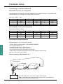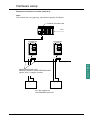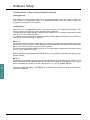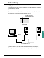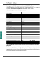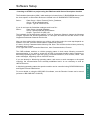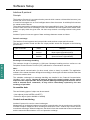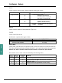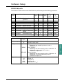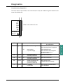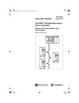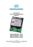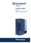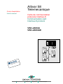
1
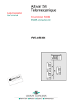
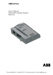
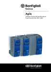
Guide d'exploitation
User's manual
Altivar 58
Telemecanique
Carte de communication
protocole Interbus-S
Communication card
Interbus-S protocol
VW3-A58304
VW3-A58304E
Merlin Gerin
Modicon
Square D
Telemecanique
Altivar 58
Carte de communication protocole Interbus-S
Communication card Interbus-S protocol
Page 2
F
R
A
N
Ç
A
I
S
Page 20
E
N
G
L
I
S
H
1
When the speed controller is powered up, the power components and some of the control components
are connected to the line supply. It is extremely dangerous to touch them. The speed controller cover must
be kept closed.
ATTENTION
After switching the ALTIVAR off and after the green LED is off, wait for 3 minutes before working on the
equipment. This is the time required for the capacitors to discharge.
E
N
G
L
I
S
H
NOTE
Although every care has been taken in the production of this document, Schneider Electric SA cannot
guarantee the contents and cannot be held responsible for any errors it may contain or for any damage
which may result from its use or application.
The hardware, software and services described in this document may be changed or modified at any time,
either from a technical point of view or in the way they are operated. Their description can in no way be
considered contractual.
20
Sommaire
Hardware setup
22
Presentation
22
Hardware setup
23
Installing the card
Hardware setup
Connecting to remote Interbus-S
23
24
24
Hardware setup
25
Software Setup
26
Configuration of the communication functions
26
Installing the environment
27
Setting up an ATV58 speed controller with IBS PC software
28
Interbus-S protocol
30
Principle
30
Accessible data
30
Control and monitoring
30
Supported services
31
DRIVECOM profile
33
Speed function
34
Fault function
36
Diagnostics
37
21
E
N
G
L
I
S
H
Hardware setup
Presentation
The Interbus-S VW3-A58304 or VW3-A58304E communication card is used to connect an Altivar 58
speed controller to Interbus-S networks.
Data exchanges enable all functions of the Altivar 58 to be used :
•
•
•
•
•
function configuration,
remote downloading of settings,
control and supervision,
monitoring,
diagnostics.
The card manages the Interbus-S communication protocol.
The card has two 9-pin SUB-D connectors : male and female. These two 9-pin SUB-D
connectors are used for daisy-chaining the Interbus-S network (1 "IN" and 1 "OUT" port)
The connection cable for the Interbus-S network must be ordered separately.
Consult the attached user's manual "Internal Communication Variables" which details :
• the speed controller control process using a serial link with the "Drivecom 21" profile,
• all Altivar 58 internal variables.
Supply:
• The VW3-A58304 card is supplied through the speed controller.
• The VW3-A58304E card contains 2 additional screw terminals for an external 24 V DC supply. It is
not supplied through the speed controller.
E
N
G
L
I
S
H
22
Hardware setup
Installing the card
Receipt
• Ensure that the card reference printed on the label is the same as that on the delivery note
corresponding to the delivery advice.
• Remove the packaging and check that the option card has not been damaged in transit.
Installing the card in the speed controller
2
3
1
Mounting precautions
• Ensure that the speed controller is powered down.
• Check that there is no voltage on the DC bus : green LED 2 (POWER) off and wait 3 minutes
after powering down.
• To access the slot for mounting the option card, unlock the protective cover 1 and pivot it.
• Place first the 50/60 Hz switch in the position corresponding to the motor as indicated in the speed
controller user's manual.
• Remove the flexible protective cover from the control card support.
• Mount the option card on the control card support by plugging it into connector
protective cover and fix it using the three screws.
3
under the
Positioning the label:
Fix the supplied self-adhesive label to the card, on the cover
of the Altivar 58 as shown opposite.
U
RC
Rd
BA
TR
POWER z
FAULT
23
E
N
G
L
I
S
H
Hardware setup
Connecting to remote Interbus-S
Male SUB-D connector pin configuration
The transmission interface is electrically isolated from the speed controller in accordance with
standard RS 485. It is available on a 9-pin SUB-D connection.
Male 9-pin SUB-D - Input
Pin
Signal
Pin
Signal
Pin
Signal
1
DO1
4
NC
7
DI1/
2
DI1
5
NC
8
NC
3
GNDI
6
DO1/
9
NC
Female SUB-D connector pin configuration
Female 9-pin SUB-D - Output
Pin
Signal
Pin
Signal
Pin
Signal
1
DO2
4
NC
7
DI2/
2
DI2
5
VCCO
8
NC
3
GNDO
6
DO2/
9
RBST
Connecting to standard RS 485 bus
Recommendations on a standard RS 485 bus
• use the Phoenix Contact cable ; reference IBS RCBxxxM
xxx = length of cable in m,
• maximum length of line : 13,000 metres,
• maximum length of drop cable : 400 metres,
• do not connect more than 256 stations to one bus,
• cable routing : keep the bus away from the power cables (at least 30 cm),
with any crossovers at right angles.
E
N
G
L
I
S
H
External supply for VW3-A58304E card
VW3-A58304E
+ -
+
-
+24 V 0 V
24
24 V DC supply (22 V mini to 25 V maxi), 200 mA mini
Note : The mass of the external 24 V DC supply must systematically be
connected to the speed controller mass.
Hardware setup
Example of connection to remote Interbus-S :
Note :
The network has a ring topology; transmission speed is 500 kbits/s.
Interbus-S module card
PLC
ALTIVAR 58
ALTIVAR 58
E
N
G
L
I
S
H
Male/female RS485 cable
Reference Phoenix Contact IBS RCB XXXM
(where "XXX" = length in metres)
+24 V
0V
+24 V
0V
24 V DC supplies for
VW3-A58304E cards only
25
Software Setup
Configuration of the communication functions
Initial power-up
The Interbus-S card is automatically recognised by the Altivar 58 on initial power-up. The card
gives access to configuration menu "8 - COMMUNICATION" from the display module (or
programming terminal or PC software).
Configuration
Select menu "8 - COMMUNICATION" to access the Interbus-S configuration parameter. This
menu is used to configure the single communication parameter.
The parameter value AdrC appears. The parameter must be set to 1 to enable transmission of data
from the bus to the speed controller.
It is used to perform modifications within the speed controller without interference from the bus or
interruption of communication on the bus.
AdrC = 0
The speed controller requests independence from the bus and the card communicates on the bus
via a limited number of services. In this status the card exchanges process data and messages with
the bus, but does not send them to the speed controller.
This status can be verified by a STATUS service. The "logical status" parameter in the reply is equal
to 2 = L_STAT_NBR_SVC_LIMIT.
With the independently supplied VW3-A58304E card, it is possible to break the power supply of the
speed controller.
AdrC = 1
The Interbus-S card sends process data and messages from the bus to the speed controller. This
status represents normal operation and can also be verified by a STATUS service. The "logical
status" parameter in the reply is in this case equal to 0 = L_STAT_COMM_READY.
E
N
G
L
I
S
H
The second parameter PrO = "INTERBUS-S" indicates that the card has been recognised but
cannot be configured.
26
Software Setup
Installing the environment
• The Interbus communication card must be configured for use by the hardware and connected to
a programmable logic controller.
• The communication bus must be connected to the card.
• The card is connected to a PC with Phoenix Contact CMD software via an RS 232 serial link.
• A VW3-A58304E card must be independently supplied in 24 V DC.
PHOENIX CONTACT
Interbus-S module card
RS 485 (BUS)
ALTIVAR 58
ALTIVAR 58
PC
E
N
G
L
I
S
H
RS 232
+24 V
0V
+24 V
0V
24 V DC supplies for
VW3-A58304E cards only
• The card is configured using CMD software with PHOENIX CONTACT documentation.
• The program is written in the PLC in accordance with the previously defined configuration and
the card is considered to be a standard I/O interface.
27
Software Setup
Setting up an ATV58 speed controller with IBS PC software
This section describes the procedure specific to the ATV58 to facilitate setup for a user who is
familiar with Phoenix Contact IBS CMD G4 > V4.3 software (English version).
• "Device Description" of the ATV58 speed controller
Device Number :
automatic
Group Number :
Station Number :
Device Name :
ATV58 Profile 21 (RB)
Manufacturer Name :
Schneider Electric
Device Type :
ALTIVAR 58
Order No :
Undefined
Ident Code :
227 (dec)
Profile Number :
21 (hex)
Process Data :
32 bits
Parameter Channel :
1 word
CR :
automatic
Interface Type...
E
N
G
L
I
S
H
Incoming Interface (IN1) :
remote
Outgoing Interface (OUT1) :
remote
Icon...
DRIVECOM 227
Parameter Channel...
Message Lengths
Transmit : 128
Receive :
Supported Parameter Channel Services
128
Read
code : 80 30 00
Write
Get-OD (long format)
• Inserting an ATV58 in a project using the automatic read function for the bus configuration :
Read again
The Read again function automatically recognises the ATV58 as a speed controller which
conforms to the DRIVECOM 21 profile (RemoteBus) with the identification code 227. Right-click
on the icon and from the menu choose Description. Next click on the Parameter Channel button,
change the Message Lengths Transmit and Receive parameters to 128 bytes and add the Get-OD
service to the Supported Parameter Channel Services list.
28
Software Setup
• Inserting an ATV58 in a project using the Edit/Insert with Device Description function
The Schneider Automation (ASA) *.mbd catalogue is located in the C:\IBSCMD\BIN directory and
the icons specific to Schneider devices are located in the C:\IBSCMD\PICTURE directory.
Select :
Data Source : Other, External_Device_Database,
Group : SE and Search button
Output : Type ALTIVAR 58, OK
If you do not have the Schneider catalogue and icons file :
Select :
Data Source : Internal Database
Group : DRIVECOM and Search button
Output : Type Profil 21 (RB), OK
The bookmark for the description appears. Click on Parameter Channel, change the Message
Lengths Transmit and Receive parameters to 128 bytes and add the Get-OD service to the
Supported Parameter Channel Services list.
After you have edited all the devices you wish to add to the project, the next step depends on
whether or not the controller board contains a parameter memory.
If it does, click on Parameterization Memory and Save. The board must have been previously
formatted using Format.
If not, right-click on the Controller Board icon, then Parameterization, Execute.
The CMD software switches to Online operating status in both cases following successful
parameterization. If you wish to access the ATV58 via message handling before switching to
Monitoring operating status, right-click on the Controller Board icon, then Control, Other... and
select messages, beginning with an INITIATE service.
If you are already in Monitoring operating status, and return to send messages to the speed
controller, the communication link is already established and it is not necessary to send an
INITIATE service.
In Monitoring operating status the speed controller can be controlled using DRIVECOM Monitor
and Digital Process Data Monitor.
For more details on using the IBS CMD G4 software, see the Phoenix Contact user's manual
(reference: IBS CMD SWT G4 UM E).
29
E
N
G
L
I
S
H
Software Setup
Interbus-S protocol
Principle
The Interbus-S protocol is a communication protocol which creates a hierarchical structure (one
master and one or more slaves).
It is used to interrogate one or more intelligent slaves from the master. A multidrop link connects
the master and the slaves.
The master manages the exchanges and has sole responsibility for them. The master repeats the
question when an incorrect exchange occurs and declares the interrogated slave absent when
there is no reply within the given time. No slave may transmit a message without having been
polled.
Interbus-S protocol uses two types of data exchange between master and slave
Periodic exchange
The Interbus-S card supports two input periodic words and two output periodic words.
The two input periodic words and the two output periodic words are assigned to the following
parameters
:
Type of Periodic
Index
Meaning
Input
0x6041
0x6044
Status word (StatusWord)
Motor speed (SpeedActValue)
Output
0x6040
0x6042
Control word (ControlWord)
Speed reference (SpeedSetP)
Exchanges via message handling
The maximum length of messages is 128 bytes. Message handling services conform to the
Peripheral Communication Protocol (PCP) standard for communication services.
E
N
G
L
I
S
H
Note :
No direct lateral communication (in other words, slave to slave) is possible. The application
software of the master has been designed accordingly to interrogate one slave and send the data
received to another slave.
The variables exchanged via message handling are detailed in the "Internal Communication
Variables" user's manual. Interbus-S protocol assigns the control register and the speed
setpoint to the output periodic words by default. Message handling must therefore not be
used to transmit these commands, as they will be immediately replaced by the next
exchange of periodics.
Accessible data
The two following types of object can be accessed :
• User objects (Index 0x5FE0 to 0x5FFF)
• Drivecom objects (Index 0x6000 to 0x6049)
Control and monitoring
Interbus-S protocol is used to control exchanges.
Management of exchanges between two entities communicating via an asynchronous serial link
includes exception responses when exchange malfunctions occur. A slave may receive various
inconsistent messages. When this happens, the slave informs the master that it cannot understand
and the master decides whether or not to repeat the exchange.
30
Software Setup
Supported services
The PCP communication services supported by the card are as follows :
Initiate :
Abort :
Status :
Get-OV :
Identify :
Read :
Write :
Initialises the communication link.
Aborts the communication link.
Speed controller and communication status.
Reads an object description.
Identifies the card.
Reads a parameter.
Writes a parameter.
A description of these services and data which may be used by the network master is given in the
list of communication links below.
List of communication links (KBL)
This list contains just one element : the Interbus-S card only supports one communication link
between a device (server) and the bus master.
A communication link defines data which can be exchanged between two devices by means of the
services and transmission/reception buffers.
Both devices must know which services are supported and the length of the buffers .
The communication link of the Interbus-S card is as follows :
Communication reference
2
Max. length of buffer in transmission mode (low priority)
128
Max. length of buffer in transmission mode (high priority)
0
Max. length of buffer in reception mode (low priority)
128
Max. length of buffer in reception mode (high priority)
0
Supported services (client)
00 00 00 hex
Supported services (server)
80 30 00 hex
Maximum number of parallel services
1
E
N
G
L
I
S
H
Initiate
Used to establish communication on the bus and authorises transmission of other services.
The parameters of this service are as follows :
Object dictionary version
10
Profile number
21hex
Supported access rights
true
Password
0
Supported group access rights
0
Note :
Sending an INITIATE message when the communication link is already established will stop the
communication (equivalent to sending an ABORT message).
Abort
Used to stop communication on the bus.
31
Software Setup
Status
Used to show the device status. Status comprises three types of data.
Data
Possible values
Logical Status
0
2
4
0
2
Speed controller status :
Speed controller ready
Speed controller not ready
Physical Status
Local details
Meaning
Communication status :
Ready to communicate
Limited number of services
Not ready to communicate
–
2 bytes
1 byte
: Speed controller fault register
: not used
Get-OV
Used to show the details of each parameter (Type, etc).
Identify
Used to identify the device.
Identification comprises three types of data :
Name of device manufacturer
Name of model
SCHNEIDER ELEC.
ATV58••••••
Device version number
V1.0 (ex)
Read / Write
E
N
G
L
I
S
H
Used to read or write the value of a speed controller or Drivecom object via its index and subindex.
The Altivar 58 "Internal Communication Variables" user's manual provides the connection
between the Index / Subindex and the speed controller or Drivecom object details.
Errors which occur in read / write are indicated by the following codes :
32
Error
class
Error
code
Additional
code
Meaning
6
7
0
Nonexistent parameter
6
6
0
Request to write an object which can be accessed in
read-only mode
5
3
0
Request to write an a parameter in local forcing
8
0
0
No response.
Software Setup
DRIVECOM profile
The Interbus-S card conforms to the DRIVECOM 21 profile and support the following parameters :
INDEX
(hex)
Name of parameter
0x6002 ProcDatEnab : Enabling of
periodics
0x603F ErrorCode
: Error code
0x6040 Controlword : Control word
Access Number Length
rights of elements (byte)
Ra/W
1
1
Type
of
Data
Type
of
Structure
SIMPLE
OS
Ra
2
2
SIMPLE
OS
Ra/W
2
2
SIMPLE
OS
0x6041 Statusword
: Status word
Ra
2
2
SIMPLE
OS
0x6042 SpeedSetP
: Speed reference
Ra/W
1
2
SIMPLE
I16
0x6043 SpeedRef
: Reference speed
Ra
1
2
SIMPLE
I16
0x6044 SpeedActV
: Output speed
Ra
1
2
SIMPLE
I16
0x6046 SpdMinMax : Minimum / Maximum
Speed
Ra/W
2
8
ARRAY
U32
0x6048 SpeedAcc
: Acceleration ramp
Ra/W
2
6
RECORD RAMP
0x6049 SpeedDec
: Deceleration ramp
Ra/W
2
6
RECORD RAMP
Characteristic
Possible
value
Access rights
Ra
W
Type of data
SIMPLE
ARRAY
RECORD
Type of Structure
BS
I16
U8
U32
RAMP
Meaning
Access in read mode
Access in write mode
Simple Variable :
Addressing the variable by Index or Index +
Subindex = 0.
Array Variable :
Addressing the entire array by Index + Subindex = 0
Addressing an array element by Index +
Subindex not equal to 0.
Record Variable :
Addressing the entire array by Index + Subindex = 0.
Addressing a recorded element by Index +
Subindex not equal to 0.
Byte String
Integer 16
Unsigned 8
Unsigned 32
Ramp (Index 21 hex)
E
N
G
L
I
S
H
33
Software Setup
Controlling the speed controller - Status machine
For information on controlling the speed controller using the Drivecom 21 profile, refer to
the Altivar 58 "Internal Communication Variables " user's manual.
"Controlword"
"Statusword"
: 6040hex
: 6041hex
Assigning process variables (Periodics)
ProcDatEnab : 6002hex
• This parameter is used to disable the assignment of periodic data to the speed controller when
written as 0. In this case, parameters 6040hex and 6042hex may be written via message handling.
If not, the written values are immediately overwritten by the next periodic data exchange.
The assignment of periodic data to the speed controller is enabled by default (factory setting).
Speed function
SpeedSetP
index 6042H
Speed
Limit
function
unit : rpm
range : -32768…32767
SpdMinMax
index 6046H
Subindex 1 and 2 :
unit : rpm
range : 0…3600
Statusword/limit value
index 6042H/bit 11
E
N
G
L
I
S
H
Ramp
function
Adjustment
and control
function
MOTOR
34
SpeedAcc
index 6048H
Subindex 1 : delta V
unit : rpm
range : 0…65535
SpeedDec
index 6049H
Subindex 2 : delta t
unit : seconds
range : 0…65535
SpeedRef
index 6043H
unit : rpm
range : -32768…32767
SpeedActV
index 6044H
unit : rpm
range : -32768…32767
Software Setup
SpeedSetP (6042hex)
The speed reference is in revolutions per minute (rpm)
Index
Subindex
Type of data
Type of structure
Meaning
0x6042
0
SIMPLE
I16
Speed reference
SpeedRef (6043hex)
The reference speed is given in revolutions per minute (rpm)
Index
Subindex
Type of data
Type of structure
Meaning
0x6043
0
SIMPLE
I16
Reference speed
SpeedActV (6044hex)
The output speed is given in revolutions per minute (rpm)
Index
Subindex
Type of data
Type of structure
Meaning
0x6044
0
SIMPLE
I16
Output speed
SpdMinMax (6046hex)
The minimum and maximum speeds are in revolutions per minute (rpm)
Index
Subindex
Type of data
Type of structure
Meaning
0x6046
1
ARRAY
U32
Minimum Speed
0x6046
2
ARRAY
U32
Maximum Speed
SpeedAcc (6048hex)
The acceleration ramp comprises a speed variation, expressed in revolutions per minute and a
time variation, expressed in seconds.
Index
Subindex
Type of data
Type of structure
Meaning
0x6048
1
RAMP
U32
Speed variation
0x6048
2
RAMP
U16
Time variation
SpeedDec (6049hex)
The deceleration ramp comprises a speed variation, expressed in revolutions per minute and a
time variation, expressed in seconds.
Index
Subindex
Type of data
Type of structure
Meaning
0x6049
1
RAMP
U32
Minimum Speed
0x6049
2
RAMP
U16
Maximum Speed
35
E
N
G
L
I
S
H
Software Setup
Fault function
ErrorCode (index 603FH)
DRIVECOM
Fault
error code abbreviation
E
N
G
L
I
S
H
36
description
DRIVECOM profile
fault description
0000
NOF
no malfunction
No malfunction
1000
CRF
load relay fault
General malfunction
1000
OLF
motor overload
General malfunction
2320
OCF
motor short circuit fault
Short circuit/short to earth
3110
OSF
mains overvoltage fault
Mains overvoltage
3120
USF
mains undervoltage fault
Mains undervoltage
3130
PHF
line phase failure
Phase failure
3310
OPF
motor phase failure
Output phase failure
3310
OBF
d.c. bus overvoltage
Output overvoltage
4210
OHF
speed controller thermal overload
Overheating device
4310
OTF
motor thermal overload
Overheating motor
5520
EEF
EEPROM memory fault
Memory EEPROM
6100
INF
internal fault
Internal software
6300
CCF
incorrect configuration (parameters)
Data Set
6300
CCI
invalid configuration (parameters)
Data Set
7300
ANF
overhauling fault
(with speed feedback)
Sensor
7300
LLF
loss of 4-20mA
Sensor
7300
TSF
PTC probe fault
Sensor
7310
SPF
speed feedback cut-off fault
(with speed feedback)
Sensor Speed
7510
SLF
standard communication link fault
Communication
Serial Interface no. 1
7520
ILF
fast communication link fault
Communication
Serial Interface no. 2
7520
CNF
fast NET communication fault
Communication
Serial Interface no. 2
9000
EPF
external fault
External malfunction
Diagnostics
Complementary diagnostics
Check the status of the 5 LEDs on the communication card, and visible through the window on the
cover of the Altivar 58.
U
RC
Rd
BA
TR
POWER z
LEDs on the Interbus-S card
FAULT
LED
Colour
U
green
Meaning
Corrective action
for malfunction
on :
The card is energised
VW3-A58304 card :
check that the Altivar is supplied
off :
reset card or
no power supply
VW3-A58304E card :
check that the card is supplied
through its independent
24 V DC source
RC
green
on :
bus remote input is
correctly connected
check the connection
Rd
red
on :
bus remote output is not
correctly connected
check the connection
BA
green
on :
Interbus interface card
is transmitting data
(Time out = 640 ms)
check that the PLC
initialises the bus correctly
TR
green
flashing : message
on the bus
E
N
G
L
I
S
H
check that the communication
link is initialised
37
E
N
G
L
I
S
H
38
VVDED397053
W9 1598008 01 11 A02
85596
1998-11